Note : Les descriptions sont présentées dans la langue officielle dans laquelle elles ont été soumises.
2176 ~ 00
IMPROVED METHOD OF REMOVING A MINABLE
PRODUCT FROM AN UNDERGROUND SEAM
Summary of the Invention
This invention relates to a method of removing minable products, such as coal,
from an
underground seam, and more particularly improvements in said method and tools
used with said
method.
The mining method of this disclosure is classified by hydraulic engineers as a
"closed flow
hydraulic system." The method employs the principles of mechanical and fluid
dynamics in a
closed conduit system under pressure and vacuum. The original invention is
described in U.S.
Patent 5,139,312 granted to the inventor. The present invention describes a
method that improves
upon the prior invention and utilized less costly tools in recovery of minable
ore, thus enhancing
cost efficiency.
As described in the referenced patent the mining process begins after having
selected a
proven geologic prospect worthy of mining such as a coal seam. The prospect
should be such
as to have a thick coal seam ( 18 inches or more) that uniformly slopes from 1
° to 90° degrees.
There should be a readily available water supply such as deep wells, lakes or
large ponds, water
filled old open strip pits or underground mines, rivers or permanent streams.
The on-site location
requires a minimum of surface disturbance usually a few acres. There is no
requirement for
settlement ponds or for disposal of waste fluids or slurry.
The first step is the drilling of a 22 inch borehole on the down dip end of
the coal seam.
The method herein discussed assumes the hole to be about 100 feet deep,
however, this method
may be applicable to much greater depths. The coal seam discussed herein is
assumed to range
2
2~ 76i 00
from 28 to 36 inches thick but, once again, this range is only assumed for
convenience. Other
22 inch drill holes will be spaced approximately 660 to 1320 feet apart in a
line paralleling the
strike of the underlying coal seam. These large diameter boreholes are used
for recovery of coal
and slurry fluids at the surface from underground coal beds, and are termed
"recovery holes."
A series of secondary 6 inch boreholes are termed "injection holes." The
number of
injection holes used in a mining unit with one recovery hole will depend on
the geology, coal
type, coal dip and thickness, mining depth, equipment size and other site
specific factors.
The equipment inserted into the recovery borehole includes a tubular collared
and jointed
shaft and a downhole recovery tool. The downhole recovery tool consists of a
bottom hole auger
device that is placed into the coal seam, extending about 12 inches below the
coal seam and 36
inches above the top of the coal seam. This bottom hole tool has a window cut
the length of the
coal bed thickness through which the coal seam is exposed to the inside. auger
tool. At the
surface of the recovery hole is placed a discharge head tool providing a
connection from the pipe
in the hole to a dredge pump and a rotary power source on the surface. Between
these two tools
are placed a column of necessary lengths of tubular collared and joined hollow
shaft for a closed
pipe system with inside auguring capabilities.
The recovery hole is first drilled about 20 feet deep into bedrock with a 22
inch bit. The
twenty foot deep hole is then cemented to the bottom with 20 inch casing. The
hole is then
drilled deeper through the surface casing with a seventeen and one-half ( 17 1
/2) inch bit to the
coal and one foot below the coal seam. Next the bottom hole tool, with the top
portion being
reduced to 12 inches, is lowered to the bottom of the hole by welding end-to-
end longer joints
of 12 inch (inside diameter) casing to make up a casing column.
3
2176100
The downhole tool with auger device has a hollow tubular shaft to which are
attached
additional sections of tubular shafts all the way to the top of the hole.
Water under pressure is pumped down the tubular shaft to exit out the water
nozzles
spaced vertically and radially outward along the shaft including the downhole
tool. The rotation
of the downhole tool auger, the pressurized water nozzles pointed upward and
the dredge pump
on the surface all work to lift the coal slurry up and out of the recovery
hole.
The initial stage of the drilling operation begins with four boreholes drilled
in close
proximity to the large diameter recovery hole, which was previously located
and staked for
drilling. The procedure of drilling commences with three 6 inch diameter
injection boreholes,
each spaced five feet apart from the recovery borehole. The 6 inch holes are
drilled in a straight
line updip and perpendicular to the strike of the underlying coal seam. Each
hole is drilled to
the bottom of the coal bed. The drilling and completion of the first two 6
inch boreholes are the
same except only one is done at a time. The first borehole is drilled through
the coal bed and
surface casing is set. Underwater explosives are placed only into the coal
seam with an electrical
detonating cap and wire lead to the surface at the top of the coal bed. Above
the explosives in
a hole is placed an inflatable five foot elongated balloon type hole plug. It
may become
necessary in some hole situations to add 3 feet of limestone stemming atop the
explosives and
then put the balloon plug in place. This balloon is attached to a small air
hose extending to the
surface where it can be inflated or deflated and retrieved when desirable. If
the injection hole
is wet and filled up to some static water level then the air balloon plug is
inflated at that point
rather than at the top of the explosives. This plugging device will
temporarily seal the hole,
thereby preventing any explosive energy from being directed up the drill hole
during the
detonation of the previously set explosive material in the coal seam.
4
2176100
Prior to detonation of any of the explosives, the large diameter recovery hole
is drilled
through the coal seam and cleaned of all material by the drilling rig. Prior
to detonation of the
explosives in the hole nearest to the large recovery hole, the drilling bit is
raised a few feet above
the coal level, but remains in the recovery hole. The nearest 6 inch hole is
then detonated. Since
the path of least resistance is toward the only void in the coal, the recovery
hole, the blasted
material will be forced to this void. Subsequent to the blast, the drilling
bit is re-lowered to the
coal seam level and any blasted material is then removed by the drilling rig
and the hole is
recleaned.
The second 6 inch injection borehole is then prepared like the first injection
hole. Again,
the recovery hole drilling rig bit is raised and the second hole is blasted.
The recovery hole is
recleaned subsequent to the blast. A third 6 inch injection hole is prepared
and blasted in the
same manner as the first two injection holes, and the recovery hole is again
cleaned by the
drilling rig. Casing is then set and cemented into the recovery hole. Bottom
hole and surface
equipment are set into place for hydraulic mining operations.
The auguring operation is then started and water is pumped down the first 6
inch open
hole. The pumped water forces the exploded coal down the coal seam to the
recovery hole auger
tool window. After a void is created from the first hole to the recovery hole,
the second injection
hole is pumped with water. The void area in the coal seam extends about 10
feet updip. The
third injection hole is likewise water pressured from the surface, forcing the
blasted chunks of
coal to the recovery hole. With the rotation of the auger, under pumped
fluids, coal is lifted to
the surface from a long channel in the coal seam.
5
2176100
The recovery hole is equipped with a pipe down the center axis of the hole all
of the way
down to the bottom hole tool. Water is forced down the hole which is forced
out the nozzles
spaced radially and vertically along the central pipe, and including the
bottom hole tool. As the
pipe rotates, it rotates the special auger device in the bottom hole tool and
it also rotates the water
nozzles. The water nozzles are pointed upward so as to inject water under
pressure up the
recovery hole, which is intended to push the coal up the recovery hole from
the coal seam.
Located radially outward from the nozzles are roller bearings which roll along
the inside of the
casing as the central pipe is rotated. The roller bearings aid in preventing
the nozzles from
impeding the rotation of the pipe and the auger in the bottom hole tool, and
also aid in
maintaining the pipe along the center axis of the recovery hole.
The operation is then temporarily delayed until both injection holes #1 and #2
are fitted
with 2 inch strands of pipe to the coal seam, where a sweep jet nozzle is
installed. These nozzles
are short and vertically adjustable to accommodate the dip angle of the coal
seam. The nozzle
jet can be horizontally rotated from the surface. The pipe and nozzles are
permanently lowered
into the hole and into the void area in the coal seam. The pipe is sealed at
the top of the surface
casing with a screw cap with bearing for a water line. The water line pipe can
be rotated through
the bearing. The nozzle can be rotated toward the recovery hole. The two
injection holes are
each connected to a surface water pump. The third injection hole is hooked up
to a third surface
pump after removal of the inflatable balloon plug. It pumps fluids down the
open hole, floating
the blasted coal chunks toward the recovery hole. It may be possible to pump
fluids down every
second or third hole rather than down every blasted hole. This depends upon
the effect of the
blast concussion and the effective radius of the explosives, and the slope or
down dip of the
seam.
6
2'.7b100
The first and second injection holes are under continuous fluid flowage from
the surface
pumps. These pumps maintain a high water pressure to the nozzles to further
pulverize the
chunks of coal at the recovery hole and in the immediately mined area. These
two injection holes
also provide the necessary volume of water slurry to maintain the void area
flow of slurry to the
recovery hole.
The recovery hole is also under continuous fluid flowage from a surface pump.
The pump
maintains a high water pressure to the nozzles which push the coal slurry out
of the bottom hole
tool up the recovery hole and out at the surface.
After the first stage of the set-up operation, the second stage of the
operation is begun.
This stage consists of drilling injection boreholes, loading them with
explosives ready to be
detonated in sequence for continuous operations. The 4th, 5th and all holes
drilled thereafter, are
drilled perpendicular to the coal strike and updip both in a straight line and
radiating from the
recovery hole. These holes are also drilled to the bottom of the coal seam,
loaded with
underwater explosives in the same manner as the first, second and third
injection holes. These
holes each contain a retrievable, inflatable five foot air balloon plugging
device for plugging the
hole at any ground water level in the hole. Explosives are then detonated by
use of a cap and
wire to the surface connected to an electrically controlled detonating device.
If the holes are dry,
it may be necessary to add a few feet of crushed limestone aggregates as
stemming on top of the
coal before setting the balloon plug. The need for the limestone stemming
depends on the
hardness of the strata on top and underlying the coal seam.
The pumped fluids will direct the blasted coal material into the previously
created void
in the coal seam and will force the coal toward the recovery hole. Since
bituminous coals are
7
2j~~~oo
usually compact, brittle, banded and have a lamellar, conchoidal, splintery
fractures and have
more or less well defined prismatic jointing, they usually will disintegrate
upon forces of
explosives and high fluid pressure into cubical or prismatic blocks along
their cleavage and joint
planes.
After the initial three injection holes are completed and the coal has been
removed from
them via the recovery hole, there will exist a 15 to 20 foot long channel in
the coal bed, updip
from the recovery hole. The next succession of injection holes will be blasted
and mining will
continue either updip, thereby creating a longer channel until the shallowest
coal is reached,
estimated some 600 feet from the recovery hole, or radial injection holes will
be blasted and the
coal adjacent to the initial channel opening will be recovered thereby
creating a wider coal seam
void. This latter method of recovery will both extend the channel updip and,
at the same time,
will expand out in a fan shape from the recovery hole.
The coal from the detonated and pressured injection holes is forced to follow
the path of
least resistance, which is toward the bottom of the recovery hole where the
coal enters the bottom
hole tool through the window of the tool. The tool is designed to crush the
coal into smaller
sizes as the auger rotates. The coal, due to its specific gravity, will free
flow in the heavy
medium slurry, up through the recovery assisted by the pressurized water
nozzle pipe to the
surface. The nozzle lift the fluid flow and prevents any blockage in the pipe.
In the upper
portion of the recovery hole pipe the dredge pump with its suction pulls the
free flowing coal and
material slurry from the hole through the discharge head tool, then forces the
slurry onto the
shaker and washing plant in a volume ratio of about 60% coal to 40% slurry
fluids.
8
?176100
Each injection hole is temporarily plugged following its detonation and coal
removed.
This is accomplished by use of an inflatable rubber device that will be placed
in the hole between
the surface and the top of the coal level, depending upon water levels in the
hole, or just above
the level where the coal seam was prior to coal removal in a dry hole
situation. The device is
then inflated and will remain in place until the hole is permanently sealed.
This device will
prevent underground fluids from exiting to the surface.
When all hydraulic mining is completed in a set of injection holes with each
large
recovery hole, the plugging of these holes is conducted by first removing the
bottom hole auger
tool and the pipe stem in the large recovery hole. The 12 inch casing in the
recovery hole may
also be removed. The recovery hole is filled with sand and gravel to within a
few feet of the
surface. If the casing is not removed then, the top three feet of casing is
cut below ground level
and the void is filled with cement. The 6 inch injection holes are then loaded
with explosives
at 10 to 20 feet above the original coal level. The exact level is determined
by calculation
dependent on the overburden material and coal seam void thickness. Upon
detonation of the
explosives in these holes, the blasted material collapses into the mining void
below. The blasted
material provides enough swell to completely fill the mine void and the
blasted area with
material, and prevents sagging of the overburden material at the ground
surface. After blasting
all boreholes, the air balloon type plugging devices and surface casing of
each hole a.re removed
and each hole is backfilled and cemented to within 2 feet of the surface.
There is essentially no slurry water or waste water for disposal at the
conclusion of a
hydraulic mining set. There is a continual loss of slurry water in the
operation due to its
replacing the coal which is removed from underground. This water will be
required to fill all
9
2~~c~1~0
voids left by coal removal in order to maintain a pressured system during
mining operations. The
slurry which is removed with the recovery of coal is recycled and goes through
the washing plant
and into a settling tank. It is then pumped back into the underground mine
area. The same water
may make several trips from the underground mine area to the surface, but will
ultimately remain
below ground to fill the void left by coal removal.
The auger tool used in this mining method consists of two separate devices
used in
conjunction with connecting pipe that is inserted into a vertical drill hole.
This system provides
an enclosed pipe passage from an underground coal bed to the surface. The
device at the surface
is termed a "discharge head tool". The device installed underground and
positioned through the
coal bed interval is called the "bottom hole tool". The bottom hole tool is
typically the same 12
inch diameter cylinder as the casing pipe in the recovery hole that is
constructed of 1/2 inch steel
pipe. The length of the bottom hole tool cylinder varies by the thickness of
the coal to be
hydraulically mined. By way of example, assuming a specific coal seam
thickness of 42 inches
a window of this length is to be cut into the cylinder. This window is
constructed by removal
of up to 1/2 of the circumference wall. The window is placed in the coal
between the top and
bottom of the coal seam and exposes the inner-workings of the cylinder to the
insitu coal. The
window serves as a passage into the bottom hole tool cylinder for chunks of
coal and water slurry
which are under hydraulic pressure during operation of the device. In viewing
the bottom hole
tool in a vertical position, the window is cut into the middle and lower
portions of the cylinder
length.
A one inch thick and 3 inch wide steel reinforcing strap is welded to the
vertical outside
edge of the window on the bottom hole tool. This reinforcement strap extends a
few inches
21761Q0
beyond the tool base for anchorage of the tool into the substrata. With this
reinforcement strap
affixed to the outside diameter of the bottom hole tool, it will typically
have a total outside
diameter of 14 inches.
The bottom hole tool used in this mining method consists of a special augering
device
where the auger is not a continuous bar spiraling around the central shaft,
but is rather made up
of segments with openings in between. In this manner the auger segments wind
around the
central shaft for only 180° and appear to be on top of each other when
viewed from above or
along the vertical axis of the auger. Upon rotation of the shaft, this auger
arrangement leaves
a gap which allow the segmented auger blades to pass above and below a tooth
like wedge
mounted on a vertical bar called a "crushing bar". The crushing bar with
spaced wedges is
welded on the opposite side of the window on the inside of the bottom-hole
tool. The crushing
bar breaks up large chunks of coal in conjunction with the action of the auger
and pushes the coal
up the backside of the bottom-hole tool to the surface by the first lifting
action of the bottom
water nozzle.
At the bottom of the open window area and below the bottom auger blade's
rotation path
is installed a deflection plate. The deflection plate is a baffle welded to
the inside of the casing.
It is a circular steel plate angling downward from the window opening. The
baffle is notched
out to allow for rotation of the central shaft, through which pressurized
water is pumped down
to exit through the nozzles. The bottom water nozzle is located below the
baffle plate and the
baffle plate acts further to prevent the pressurized water from the lowest
nozzle to be forced out
into the coal seam through the window area.
11
21761~r,
Also below the window section and the bottom end of the cylinder is a pipe
section that
houses a bearing and bottom end assembly for holding the lower end of the
auguring device.
There is a special segment at the top of the bottom hole tool adjusting the
outside diameter from
20 to 12 inches in diameter so additional sections of 12 inch pipe casing can
be joined to the
bottom hole tool for connection of it to the surface discharge head tool.
The top of the auger is connected by a shaft to a rotary power source.
The bottom hole tool auger is a segmented steel auger. It is constructed from
segments
of augers by positioning one segment above the other and each are welded onto
a common
hollow steel shaft. The two auger segments are serrated with notches. These
notches are
preferably reinforced along the sides with hard alloyed welding material. The
serrated rim of the
auger, when rotated, crushes the inflowing solid coal and slurry material that
has reached the
auger through the window. The crushed material is then lifted to the surface
by pressure flow
assisted by the rotating auger segments and the pressurized water from the
nozzles.
The discharge head tool includes a discharge elbow pipe device which is placed
at the
surface of the hole through which the coal and slurry material is pushed by
water pressure and
assisted by the rotating auger segments. The discharge head tool is secured to
the top of the
recovery pipe in the hole and is constructed of 90 degree L-shaped pipe with a
steel constructed
rectangle box welded onto the outside of the "L" bend of the pipe. The elbow
pipe and box
typically have 1/2 inch thick walls with a 5 inch hole cut out of the center
of the box top and
through the convex bend of the pipe. when the discharge head tool device is
connected to the
pipe in the hole, the 5 inch hole will be positioned in the center of the 12
inch pipe base for
inserting the auger shaft up through the steel box. The auger shaft end will
then be connected
to a rotary power source.
12
CA 02176100 2006-O1-09
65224-533
At the top of the steel box is a bearing and seal
cage to prevent leakage of gases when handling vacuum
pressured fluids. The discharge head tool ensures a closed
fluid flowing system. The discharge head tool is adapted
with rotary motion components from outside to auger inside.
The smaller 8 inch diameter end of the tool is attached to a
dredge pump. The rotary power unit for operating the auger
is a hydraulic motor with a gear box connected to the 5 inch
auger shaft.
The improvements of this invention over the prior
method provide for a recoverable bottom hole tool, a smaller
angering device present only within the bottom hole tool as
opposed to an auger the full length of the recovery hole and
the modification of the bottom hole tool auger such that it
consists of auger segments, a crushing bar, a baffle and a
bottom hole water nozzle each intended to improve the
recovery of the coal slurry and reduce cost of the mining
operation described.
Dimensions given in this summary are by way of
example only and are illustrative of typical sizes of
structures for practicing the methods of this disclosure.
For reference to other methods and apparatus for
removing a minable product from an underground seam
reference may be had to the following United States Patents:
4,396,075; 4,252,200; 4,421,182; 4,804,050; 4,433,739;
4,629,011; 4,348,058; 4,449,593; 4,411,474; and 4,330,155.
According to one aspect of the present invention,
there is provided a bottom hole tool for removing fractured
minable product from an underground seam, in which the seam
is penetrated by a hole drilled substantially vertically
from the earth's surface, comprising: an upright tubular
13
CA 02176100 2006-O1-09
65224-533
body having a tubular axis, having a top end and a bottom
end and having a tubular wall, the wall having an elongated
vertical opening therein of width less than substantially
one-half of the circumference of the tubular wall; an auger
positioned in said tubular body, the auger having an axis of
rotation that is substantially coincident with the tubular
axis of said body and of diameter less than the internal
diameter of said tubular body, the auger having a top end
and a bottom end, the length of the auger being at least the
length of said tubular body opening; blades of said auger
extending only one-half way around the circumference of a
central shaft and positioned in such a way as to be on top
of each other when observed from the tubular axis of said
auger; a hollow central shaft through which water may be
injected; a nozzle with one end attached to the central
shaft and the other end radially outward and pointing
upwards toward the top end of the auger, such that water
injected down the hollow central shaft would be ejected
upward by means of the nozzle, said nozzle located above the
bottom of said tubular body but below a lowest auger blade
segment, said nozzle being rotatable within the bottom hole
tool as the auger is rotated; a flange attached to a bottom
edge of the elongated vertical opening, said flange
extending inwardly and downward from the opening to within a
close proximity of a central shaft outer diameter means to
rotate said auger; a crushing bar conformably attached to
the inside wall of said tubular body opposite said vertical
opening, said crushing bar having protrusions mounted
thereunto spaced vertically along said bar, between rotating
auger segments; and means to attach said tubular body top
end to conduit means extending from the earth's surface.
According to another aspect of the present
invention, there is provided a method of removing a minable
13a
CA 02176100 2006-O1-09
65224-533
product, such as coal, from an underground seam of minable
product, comprising the steps of: drilling a substantially
vertical recovery hole from the earth's surface through a
seam of minable product; installing in the recovery hole a
bottom hole tool, an outer diameter of said tool being
larger than the diameter of a casing of the recovery hole;
said bottom hole tool having an elongated opening of
substantially one-half the circumference of said tool, the
opening positions toward an ore seam; said bottom hole tool
being equipped with an auger device and a means for
supporting said auger device and rotating same; said means
of rotating said auger comprising a hollow pipe with
connections from said bottom hole tool to the earth's
surface; nozzles mounted radially outward from said hollow
pipe spaced along the length of said pipe from the bottom of
the bottom hole tool below blades of the auger along the
pipe to the surface, said nozzles forcing water up the
recovery hole; drilling a plurality of closely spaced-apart
injection holes from the earth's surface through the seam of
minable product, the injection holes being drilled in a
pattern extending from said recovery hole; inserting an
explosive in said seam of minable product where penetrated
by each of said injection holes; sequentially igniting the
explosive in each of the injection holes to blast fractured
minable material from said seam; injecting water
sequentially in said injection holes to move fractured
minable material toward said recovery hole; and operating
the recovery hole auger and injecting water down a central
hollow pipe and upward through the nozzle to raise said
fractured minable material to the earth's surface.
A better understanding of the invention will be
obtained from the following description of the preferred
embodiments taken in conjunction with the attached drawings.
13b
2176100
Description of the Drawings
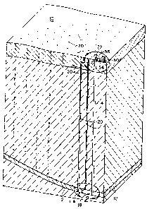
Figure 1 is an isometric view showing a cross-section of a section of the
earth from the
surface to slightly below an underground seam of minable materials, such as a
seam of coal, and
showing some of the basic equipment utilized in the method of this invention.
Figure 2 is an enlarged partial view taken at 2 of Figure 1 showing a bottom
hole tool in
place and showing the method of removing minable material from the seam.
Figure 3 is an enlarged partial view taken at 3 of Figure 1 showing, in
elevational view,
some of the surface equipment as utilized in practicing the method of this
invention.
Figure 4 is an enlarged elevational partially cross-sectional view of a bottom
hole tool as
employed in this invention.
Figure 5 is a cross-sectional view taken along the line S-5 of Figure 4.
Figure 6 is a diagram showing the flow of water as used in the mining method
for
removing a minable product from an underground seam.
Figure 7 is a plan view of a system for practicing the method of this
invention showing
diagrammatically the layout of a field to be mined and the equipment located
at the earth's
surface for conducting the mining operation.
Figure 8 is an enlarged cross-sectional view of the discharge head tool as
used in the
method of this invention.
14
2176100
Description of the Preferred Embodiment
Referring to the drawings and first to Figure 1, a cross-sectional section of
a surface area
of the earth is illustrated, the earth's surface being indicated by the
numeral 10 and an
underground seam of minable products being indicated by the numeral 12. While
this invention
can be practiced to recover various mining products, it is particularly
applicable for mining coal.
The invention will be described as it pertains to mining coal, it being
understood that instead of
coal other minable products can be recovered by the method of this invention.
However, the
invention is particularly useful for coal because the specific gravity of coal
makes it easy to move
by flowing water, whereas recovery of minable products of greater density
would be much more
difficult when attempted to be recovered by the principles of this disclosure.
The objective is to move to the earth's surface coal from seam 12 without
following the
usual mining processes, that is, without removing the overburden and then
recovering coal that
is usually termed "strip mining process", or without conducting underground
passageways wherein
miners operate. Instead, the method of this invention is to provide means for
recovering coal
from seam 12 wherein the surface of the earth is hardly disturbed and wherein
it is not necessary
for any miner to go below the earth's surface.
The first step in practicing the method of this invention is to drill a
relatively large
diameter substantially vertical borehole, which is termed a "recovery hole"
indicated by the
numeral 14. The recovery hole 14 extends from the earth's surface 10 to
slightly below coal
seam 12. The recovery hole is preferably formed utilizing a relatively large
diameter surface pipe
16, such as a pipe of about 20 inches in diameter, for a relatively short
distance, such as about
20 feet. The surface pipe is cased or cemented in the borehole.
217100
Thereafter, a somewhat smaller diameter borehole extends from the surface pipe
to slightly
below the bottom of seam 12. A casing, which may typically be 12 inches in
diameter, extends
within the surface casing through the seam.
The basic principle of this invention is to fragment coal in coal seam 12 by
explosives and
to move the fragmented coal from the seam to a bottom hole tool 18 positioned
at the lower end
of recovery hole 14 by which the fragmented coal is removed. In order to
fragment the coal
within coal seam 12, a plurality of injection holes 20 are drilled in spaced
apart relationship and
in a pattern with respect to recovery hole 14. Each of the injection holes 20
is drilled from the
earth's surface 10 and into coal seam 12. Explosives are then positioned in
the coal seam
through the injection holes and the explosives ignited to fragment the coal,
after which water is
inserted through the injection holes 20 to move the fragmented coal to bottom
hole tool 18. All
of these steps and the apparatuses used in practicing the steps will now be
described.
Referring to Figures 2, 4 and 5, bottom hole tool 18 will be described.
Positioned within recovery hole 14 is large diameter casing 22. At the lower
end of
casing 22, as seen best in Figure 4, is a tubular body 24 which must be larger
than the diameter
of casing 22. A special reducer coupling is employed to connect the segments.
Window 32 is in the form of a cut out of the wall of tubular body 24. The cut
out should
be approximately the height of seam 12.
Coaxially supported within tubular body 24 is a shaft 34. The shaft is
supported by a
lower bearing 36. The shaft 34 may be formed of a length of pipe, such as 4
inch diameter pipe.
The pipe is then attached to other sections of the diameter pipe the full
length of the recovery
hole. Formed on shaft 34 is an auger blade and in the preferred arrangement as
illustrated, the
16
217100
auger is comprised of semicircular segments positioned such that viewed along
the vertical axis
of the auger, the segments overlap each other. The auger blade segments 42
have internally
formed teeth 46 on the external peripheral edge.
Welded on the exterior of tubular body 24 are vertical reinforcing straps 48A
and B.
These reinforcing straps are welded to the vertical outside edge of window 32
and serve to resist
deflection of the tubular body and extend into the subsoil below coal seam for
anchoring.
Welded to the interior of the bottom hole tool casing is a reinforcing bar 47
shaped
conformably the interior of said casing, to which are mounted conical shaped
steel protrusions
49 which act to help break up any larger pieces of coal or other ore.
Referring to Figures 3 and 8 details of a discharge head tool, generally
indicated by the
numeral 50, are shown. Casing 22 extends upwardly through the surface pipe 16.
Above the
earth's surface 10 a flange 52 is affixed to the casing. Attached to flange 52
is a tubular elbow
member 54, the first end 54A thereof being attached to the flange and the
elbow member having
a second end 54B that is connected to a short -length of pipe 56. The intake
58 of a dredge pump
60 is secured to the other end of pipe 56.
Tubular elbow member 54 has an opening 62 that communicates with a housing 64
affixed to the exterior of the elbow member.
Positioned within casing 22 is a vertical shaft 66 through which water under
pressure is
piped and to which are mounted nozzles 68 spaced axially and radially. The
nozzles extend from
one directly above the bottom bearing in the bottom hole tool and thence along
the shaft to
adjacent the earth's surface. As shown in Figure 8 shaft 66 extends through
opening 62 and
through the opening in housing 64 and receives a sealed bearing 70. The shaft
is then attached
17
2176100
to a hydraulic driven speed reducer, which is illustrated emblematical at 72.
By power supplied
by speed reducer 72, shaft 66 and thereby nozzles 68, attached to it are
rotated. In addition, the
lower end of shaft 66 is affixed to the bottom hole tool shaft 34 to thereby
also rotate auger
blades 42.
A plan view for a basic system for practicing the invention is shown in Figure
7. The
recovery hole is indicated at 14 and a plurality of injection holes 20 are
shown. Pipe 56
extending from the recovery hole connects to dredge pump 60 as previously
described. From
dredge pump 60, a slurry line 73 connects to a shaker 74 for separating
fragmented coal from a
slurry. The coal passes by way of conveyor 76 to a rotator breaker 78. Rock
separated by the
rotator breaker is fed by a conveyor 80 to a rock storage refuge 82. The
separated coal is fed
by conveyor 84 to a slacker 86. In addition, from shaker 74 a slurry line 88
feeds to a washing
plant 90 where the separated coal is washed. By conveyor 92, coal is fed to a
de-watering screen
and drier 94. From drier 94 the recovered coal is fed by conveyor 96 to
slacker 86.
A water tank 98 provides a water reservoir. Drainage from the washing plant
and de-
watering screen are fed by conduits 100 into the watering tank. From the
watering tank pumps
102 and 104 supply a distribution pipe 106 that has facilities for connection
of water to the input
of the injection holes, as well as for the nozzles in the recovery hole.
A source of water 108 which can be a well, a lake, a river, or the like, is
used to provide
water for the mining operation. Pump 110 connects water to the distribution
pipe 106 and can
be used to fill tank 98 by way of water supply 112.
The plant lay out of Figure 7 is representative of means of equipment used for
practicing
the invention.
18
2176100
Figure 6 is a flow diagram of water as employed in the system. All water is
recycled and
the only water loss, as will be described subsequently, is that which is used
to fill the seam as
coal is removed.
The physical apparatuses and system for employing the method of the invention
having
been described, the basic method will now be set forth. First, a large hole is
drilled for a
relatively short depth and a surface pipe 16 is set in the hole. Then a
recovery hole 14 is drilled
through the surface pipe and extends to just below coal seam 12. The equipment
of Figures 2,
4 and 5 are installed in the recovery hole 14 in the arrangement previously
described, that is, the
bottom hole tool 18 is installed with the connecting casing and the surface
equipment is installed
at the recovery hole as shown in Figure 3.
Injection holes are drilled adjacent the recovery hole and typically spaced,
such as about
five feet, from the recovery hole. While recovery hole 14 is preferably
drilled substantially
vertically, the injection holes are preferably drilled to intercept seam 12
perpendicularly thereof.
Explosives are placed in the injection holes and detonated to fracture coal
from the coal seam.
Water is then injected into the injection holes to move the fractured coal to
bottom hole tool 18.
Figure 1 shows the system after the first injection holes nearest the recovery
hole have
been detonated, providing a clear area 114. The fragmented coal in the space
between the point
of detonation and the recovery hole is moved in the direction toward the
recovery hole by the
flow of water. After detonation, water is injected into all or a portion of
the injection holes to
move the fragmented coal to the bottom hole tool 18. At bottom hole tool 18
the coal is carried
through open window 32 to contact auger blades 42. Water under pressure
ejected by the bottom
nozzle 44, helps to move the coal upwardly into the interior of the bottom
hole tool 24 and
further upwardly into the interior of the casing 22 are thence to the surface.
The bottom flange
45, provides a buffer to keep the bottom water nozzle 44 from ejecting the
coal out of the
19
21761 QO
window of the bottom hole tool. Any fragments of coal that are too large to be
carried upwardly
by the auger are severed and further fractured by auger blades 42 having teeth
46 thereon to
break up the coal and further by the crushing bar 47. The hydraulic pressure
within the system
as well as the rotating auger, the rotating water nozzles in the recovery hole
all help to move the
coal and slurry to the earth's surface.
As the drilling operation proceeds the injection holes, which are used for the
placement of
explosives and then subsequently used for the injection of water, are sealed
as further injection
holes are employed since water must be injected at the farthest point from the
recovery well
where fragmented coal exists. Closure or plugging of the injection holes 20
can be accomplished
utilizing an inflatable plugging tool.
The method of this disclosure is preferably practiced in a coal seam that is
not horizontal
but which has an up slope. The recovery hole 14 is positioned at the lowest
point in the field
to be mined and injection holes are drilled in patterns from the recovery hole
14 up slope of coal
seam 12. In this way, water injected into the coal seam to move fragmented
coal always moves
the coal downwardly in the direction toward the recovery hole.
A single recovery hole may be employed with a large number of injection holes
so that
a single recovery hole can be used to mine a relatively large acreage.
Naturally, as the
fragmented coal must be moved at greater distances from the place where it is
fragmented from
the coal seam by an explosion to the recovery well, the efficiency of movement
begins to
decrease.
21761 Ou
After a field has been mined to the extent commercially feasible utilizing a
recovery hole,
a new recovery hole is drilled and the entire procedure repeated.
When the use of the injection and recovery holes has been completed, they are
plugged
so as to prevent contamination of water supplies. In addition, after a field
has been mined
utilizing the techniques herein explosives can be set off in the injection
holes above the coal seam
to blast rock loose to fall in and fill the evacuated coal seam.
When the entire drilling procedure is completed, all equipment can be removed
and the
surface of the earth is left substantially undisturbed. All of the recovery
holes and injection holes
are plugged and pipe removed well below plow depth so that almost no
environmental damage
is caused by the mining procedures of this system.
The claims and the specification describe the invention presented and the
terms that are
employed in the claims draw their meaning from the use of such terms in the
specification. The
same terms employed in the prior art may be broader in meaning than
specifically employed
herein. Whenever there is a question between the broader definition of such
terms used in the
prior art and the more specific use of the terms herein, the more specific
meaning is meant.
While the invention has been described with a certain degree of particularity,
it is manifest
that many changes may be made in the details of construction and the
arrangement of components
without departing from the spirit and scope of this disclosure. It is
understood that the invention
is not limited to the embodiments set forth herein for purposes of
exemplification, but is to be
limited only by the scope of the attached claim or claims, including the full
range of equivalency
to which each element thereof is entitled.
21