Sélection de la langue

Search

Sommaire du brevet 2176965 

Énoncé de désistement de responsabilité concernant l'information provenant de tiers

Une partie des informations de ce site Web a été fournie par des sources externes. Le gouvernement du Canada n'assume aucune responsabilité concernant la précision, l'actualité ou la fiabilité des informations fournies par les sources externes. Les utilisateurs qui désirent employer cette information devraient consulter directement la source des informations. Le contenu fourni par les sources externes n'est pas assujetti aux exigences sur les langues officielles, la protection des renseignements personnels et l'accessibilité.

Disponibilité de l'Abrégé et des Revendications

L'apparition de différences dans le texte et l'image des Revendications et de l'Abrégé dépend du moment auquel le document est publié. Les textes des Revendications et de l'Abrégé sont affichés :

  • lorsque la demande peut être examinée par le public;
  • lorsque le brevet est émis (délivrance).
(12) Demande de brevet: (11) CA 2176965
(54) Titre français: PROCEDE ET DISPOSITIF D'EVAPORATION
(54) Titre anglais: EVAPORATION MEANS AND METHOD
Statut: Réputée abandonnée et au-delà du délai pour le rétablissement - en attente de la réponse à l’avis de communication rejetée
Données bibliographiques
(51) Classification internationale des brevets (CIB):
  • C02F 01/04 (2006.01)
  • B01D 01/06 (2006.01)
  • B01D 03/00 (2006.01)
(72) Inventeurs :
  • VUONG, DINH-CUONG (Etats-Unis d'Amérique)
(73) Titulaires :
  • TEXACO DEVELOPMENT CORPORATION
(71) Demandeurs :
  • TEXACO DEVELOPMENT CORPORATION (Etats-Unis d'Amérique)
(74) Agent: SMART & BIGGAR LP
(74) Co-agent:
(45) Délivré:
(86) Date de dépôt PCT: 1994-11-18
(87) Mise à la disponibilité du public: 1995-06-01
Requête d'examen: 1996-08-09
Licence disponible: S.O.
Cédé au domaine public: S.O.
(25) Langue des documents déposés: Anglais

Traité de coopération en matière de brevets (PCT): Oui
(86) Numéro de la demande PCT: PCT/US1994/013378
(87) Numéro de publication internationale PCT: US1994013378
(85) Entrée nationale: 1996-05-17

(30) Données de priorité de la demande:
Numéro de la demande Pays / territoire Date
08/155,364 (Etats-Unis d'Amérique) 1993-11-22

Abrégés

Abrégé français

Evaporateur (11) dans lequel une chambre (72) sert à recevoir l'eau devant être évaporée. Lorsqu'on chauffe plusieurs tubes (60) de l'évaporateur et que l'eau coule sur une paroi interne d'un tube, ceci a pour effet d'évaporer au moins une partie de cette même eau. Plusieurs distributeurs (100) relient dans l'espace la chambre pour l'eau aux tubes de l'évaporateur de sorte que chaque distributeur (100) distribue uniformément l'eau depuis la chambre pour l'eau jusqu'à une paroi interne d'un tube correspondant. Une source de chaleur sert à chauffer la pluralité de tubes à une température d'évaporation. Un appareil distille la vapeur d'eau résultant de l'évaporation de l'eau pour produire de l'eau distillée.


Abrégé anglais


An evaporator (11), which includes a water chamber
(72) for receiving water to be evaporated. A plurality of
evaporator tubes (60) which when heated, and when water is
on an inner wall of a tube, evaporates at least a portion of that
water. A plurality of distributors (100) spatially connecting
the water chamber with the evaporator tubes in a manner so
that each distributor (100) uniformly and distributes the water
from the water chamber to an inner wall of a corresponding
evaporator tube. A heat source, which heats the plurality of
tubes to an evaporation temperature. Apparatus distills the
water vapor resulting from the water evaporation to provide
distilled water.

Revendications

Note : Les revendications sont présentées dans la langue officielle dans laquelle elles ont été soumises.


WHAT IS CLAIMED IS:
1. A distillation apparatus comprising:
water means for receiving water to be
distilled,
means for evaporating water when heated
comprising a plurality of tubes for providing a water vapor,
a plurality of distributor means apatially
related to the water means and to the plurality of tubes, each
distributor means being means for uniformly distributing water
from the water means to an inner wall of a corresponding tube,
comprising a single molded body including:
(i.) a first passing means portion
perpendicular to a longitudinal axis of the corresponding tube,
having holes arranged in a pattern,
(ii.) a second cylindrical portion extending
into the corresponding tube,
(iii.) a third truncated conical portion
having a conical angle with the longitudinal axis of the
corresponding tube to direct the passed water from the passing
means to move downward and outward, and
(iv.) a fourth disk shaped portion having
a diameter perpendicular to the longitudinal axis of the
corresponding tube, sufficiently smaller than the diameter of the
corresponding tube so as to direct water in a substantially
horizontal direction to encounter the inner wall of the
corresponding tube,
heat means for heating the plurality of tubes
to an evaporation temperature, and
means for condensing the water vapor from the
plurality of tubes to provide distilled water.
2. Cancelled.
-5-

3. Cancelled
4. The distillation apparatus of claim 1 wherein in
the passing means there are eight holes uniformly horizontally
spaced around the longitudinal axis of the corresponding tube.
5. The distillation apparatus of Claim 4 in which the
diameter of each hole is 5/16 inches.
6. The distillation apparatus of Claim 5 in which not
all of the water provided to the plurality of tubes is evaporated
so that some water issues from the plurality of tubes, and
further comprising means for removing salt from the water issuing
from the plurality of tubes.
7. Cancelled.
8. Cancelled.
9. Cancelled.
10. Cancelled.
11. Cancelled.
12. Cancelled.
13. Cancelled.
- 6 -

Description

Note : Les descriptions sont présentées dans la langue officielle dans laquelle elles ont été soumises.

-. ~211~=965 P(~T/US 94/13378
2aJU~Is~
EV~P~TION M~Nr. P~ Ml3THOD
BACRGRO~lND OF ~ , N V ~' '` L .! U.
Field of the Inve~tiQn
The present invention relates to all distiIlation
means and methods in general and, more particularly, to
evaporation .
~al7Y 01~ l~Ti! lNVJ!.l~L10~, j ~
An evaporator, w}~ich ~nr~ - a water chamber for
receiving water to be evapo~-ated. A plur~lity of evaporator
tubes which when heated, and when water i8 on an inner wall
of a tube, evaporates at least a portion of that water. A
plurality of distributors spatially connecting the water
ch~mber with the evaporator tubes in a manner 80 that each
distributor lln; fo~mly distributes the water from the water
chamber to a~ inner wall of a COL~ ;n~ evaporator tube.
A heat source, which heatf; the plurality of tubes to an
evaporation temperature. Apparatus rrn~nR9~ the water
vapor resulting frQm the water evaporation to provide
distilled water.
The objects and advantages of those inventions
will appear more fully here!inafter from a crn~ ation of
details of description which follows, taken together with
the Al-_ _ ying drawings, wherein one -';-- t of the
invention is illustrated by way of example. It is to be
expressly understood, howe-rer, that the drawings are for
illustration purposes only and are not to be construed as
f~n;n~ the limitg of the invention.
DES~rKI~Ll~ OF TH3 DRAWTt- '
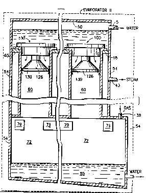
Fig. 1 is a partial 8; _ l; fied block diagr~m and
a partial schematic of an 13vaporation system l~ 7;ng an
evaporator constructed in accordance with the present
invention .
Fig. 2 is a diagra~matic r_~Le_ .t~tion of the
evaporator shown in Fig. 1.
Fig. 3 is a cut-~way drawing alo~g the line 3-3 in
the direction Of. the arrows shown in Fig. 4 of the
distributor shown in Fig. 2.

r ~; ~ t ~ r P C 1~ / U S 9 4 / 1 3 3 7 8
21~6~65 IP~ S 2~JUN'~5
Fig. 4 is a top view of the distrib~r~r lsnown ln
Fig. 2.
L)eS' VTV~lC1N OF T~IE lNV~Ll~N
Generally waste ~rater has to be handled under
current environmental regulaLtory actions. One such process
uses an evapor~Ltor for zero discharge of waste water which
Lea~,vc:Ls clean water for reuse as intake water in the
discharging facility and rlaking a low volu~e byproduct
stream for _inal ~; ~pos-l or resource L~COvt:~ y . The leading
terhnnlogy is waste water dil3~ t;nn~ which produces clean
distilled water ~Lnd rnnr~nt~-ated brine r!Ls a Ly~-~d~-;l.. The
evaporator is a water film evaporator in which the water
falls on the inside o_ ev~r~rator tubes which are heated by
stea~rL to provide the evapor~Ltion. The hot brine and water
vapors exits from the bottoIl of the evaporator tube and ~Lre
separ2Lted in the brine removal Le~Lns. A portion of the
brine is blown down as product brine and ~Lost of the brine
is recirculated by the brine pump back up to the top of the
tube. If the water is ~ot effectively provided to an
evaporator tube, particularly for waste water, which
rnn~J~;n~ fouling and scaling materi~Lls, those materials are
deposited on the sides of the evapor~Ltor tube. The water is
r~ n~d to flow lln~ formly to prevent local areas of high
concentration of dry-ness ~rhich would lead to scaling or
_ouling at those points and thus, the 1088 of heat transfer.
The present invention achi~ves a unifor~L flow of water in
the evaporator tubes there]~y increasing the e__iciency of
evapor2Ltion and m;n;m; 7;n~ fouling and scaling of the
evaporator tube.
With reference to Fig 1, there is shown a
conv^nt~nn~l-type evaporation system in which wator enters
an evaporator 11 through lines 1 and 5. Evaporator 11 is ~L
conv~n~; nnol -type evaporator except as '; f~ 1 in
accordance with the prer3ent invention which will be
explained in greater detail later. The object of evaporator
11 is the evaporation o'E water; however, brine still
~r 1 :~tes in evaporator 11. The brine ~r 1 S~tion is
recirculated via line 14 by ~, pump 15 and pumped through
brine removal means 22 where the water is then returned by
~dE~DE~ S~lEr
_ _ , _ ,,,

21;r69~s PCTIUS 94/13378
; IP~A/US 2 0 Jl,lN 1995
line 25 to line 5. Also shown in Fig. 1 are distillate
rec,,v_ y mean~ 36 which c~ndens~s the water vapor co~ing
from evaporator 11 via line 38. The evaporation within
evaporator 11 occurs due t.o the steam heat provided by a
steam source 42 via line 43.
Referring now to ~Fig 2, evaporator 11 is shown as
having vertical separ~tion by cut-away lines and h~orizontal
separation by cut-away line3. The vertical separation is to
indic~te that there is a plurality of tubes used for
evaporation. The horizontal separation is to indicate th~t
there is great length to these tubes, some of them 20 to 30
feet in length, and also t~ show the water ~c 1 ~tion 85
at the bottom of evaporator 11.
Water evaporator 11 ;n~ a dome 50 which is
connected to and sealed with ~t~ 54 of evaporator 11.
A plurality of tubes 60 ill held in place by a plate 65.
Tubes 60 extend down to a chamber 72. Loc~ted in chamber 72
are conv~n~ n~l demisters 79, which perform the functions
of vapor/liquid separation.
lIeretofore, an a Ic-n.y~ ~ providing water to each
tube was general in nature ~nd it was such that it caused
water to run down one location within a tube.
The present invenltion is a fluid distributor 100.
Referring to Figs. 3 and 4 as well, Fig 3 is a cut-away view
of distributor 100 in the direction of lines 3-3 shown in
Fig. 4. As shown in Fig. 3, distributor 100 is a one piece
unit, lded 80 that it fits inside of an evaporator tube 60
supported by the ~,v~ ~g 105. A horizontal portion 110 is
formed having holes 115 therethrough. A preferred hole
aL C.LIy. t is a pattern of eight holes, each hole aL. ~Lg._d
~long a radius from a horizontal center of dlstributor 100
having a 45 relat;~n~l~;r t~ the radii on each side of it.
Each hole also has a 5/16 inch diameter.
There is a lower t:runcated conical portion 126 of
distributor 100 which flares out at approximately 45 from
a vertical cylindrical portion 131. Another horizontal
portion 139 provides the bottom end o~ distributor 100. The

WO 95/14518 2 ~ 7~ 9 ~ 5 ~ PCT/US94113378
o~l 1loq(eS "' ~ '
vertical portion 131 ensures that the distribution of water
is definitely into evaporator tube 60.
Some other dimenlsions of distributor 100 that have
been used are along the lilles for an evaporator tube 60, are
an outer diameter of two ' inches and an inner diameter of
1.944 inches. The maximum diameter of hori20ntal portion
110 is substantially the same as the inner diameter of
evaporator tube 60. ~ow~ver, it should be further noted
that the bottom horizontal element 139 has a diameter of
1.756 inches while the junction of the 45~ of the conical
portion 126 has a diameter of 1.5 inches, but leaves a
little lip at the end of the conical section 126. ~he
dif ference between the diameter of the horizontal bottom
portion of distributor 100 and wall 61 of evaporator tub 60
creates a gap of approximately 3/32.
Thus, as shown by arrows in Fig. 2, the water
passes straight down from holes 115 and meets conical
section 126 where the water is directed downward and
outward. The water flows downward and outward until it
counts bottom horizontal element 139 which causes the water
to flow out in a general hl~rizontal direction subj ect to the
pull of gravity over thal: gap of 3/32 inches. The water
then comes in contact with wall 61 of evaporator tube 60 and
~low5 ~awn w~ll ~1.

Dessin représentatif
Une figure unique qui représente un dessin illustrant l'invention.
États administratifs

2024-08-01 : Dans le cadre de la transition vers les Brevets de nouvelle génération (BNG), la base de données sur les brevets canadiens (BDBC) contient désormais un Historique d'événement plus détaillé, qui reproduit le Journal des événements de notre nouvelle solution interne.

Veuillez noter que les événements débutant par « Inactive : » se réfèrent à des événements qui ne sont plus utilisés dans notre nouvelle solution interne.

Pour une meilleure compréhension de l'état de la demande ou brevet qui figure sur cette page, la rubrique Mise en garde , et les descriptions de Brevet , Historique d'événement , Taxes périodiques et Historique des paiements devraient être consultées.

Historique d'événement

Description Date
Le délai pour l'annulation est expiré 1998-11-18
Demande non rétablie avant l'échéance 1998-11-18
Réputée abandonnée - omission de répondre à un avis sur les taxes pour le maintien en état 1997-11-18
Toutes les exigences pour l'examen - jugée conforme 1996-08-09
Exigences pour une requête d'examen - jugée conforme 1996-08-09
Demande publiée (accessible au public) 1995-06-01

Historique d'abandonnement

Date d'abandonnement Raison Date de rétablissement
1997-11-18
Titulaires au dossier

Les titulaires actuels et antérieures au dossier sont affichés en ordre alphabétique.

Titulaires actuels au dossier
TEXACO DEVELOPMENT CORPORATION
Titulaires antérieures au dossier
DINH-CUONG VUONG
Les propriétaires antérieurs qui ne figurent pas dans la liste des « Propriétaires au dossier » apparaîtront dans d'autres documents au dossier.
Documents

Pour visionner les fichiers sélectionnés, entrer le code reCAPTCHA :


Pour visualiser une image, cliquer sur un lien dans la colonne description du document. Pour télécharger l'image (les images), cliquer l'une ou plusieurs cases à cocher dans la première colonne et ensuite cliquer sur le bouton "Télécharger sélection en format PDF (archive Zip)" ou le bouton "Télécharger sélection (en un fichier PDF fusionné)".

Liste des documents de brevet publiés et non publiés sur la BDBC .

Si vous avez des difficultés à accéder au contenu, veuillez communiquer avec le Centre de services à la clientèle au 1-866-997-1936, ou envoyer un courriel au Centre de service à la clientèle de l'OPIC.


Description du
Document 
Date
(aaaa-mm-jj) 
Nombre de pages   Taille de l'image (Ko) 
Dessin représentatif 1997-06-25 1 17
Dessins 1995-05-31 3 68
Description 1995-05-31 4 178
Abrégé 1995-05-31 1 63
Revendications 1995-05-31 2 58
Courtoisie - Lettre d'abandon (taxe de maintien en état) 1997-12-15 1 185
Taxes 1996-10-06 1 35
Rapport d'examen préliminaire international 1996-05-16 18 615
Correspondance de la poursuite 1996-08-08 1 46