Note : Les descriptions sont présentées dans la langue officielle dans laquelle elles ont été soumises.
2177121
METHOD AND APPARATUS FOR FEEDING REACTION GAS AND SOLIDS
The present invention relates to a method and apparatus for feeding reaction
gas
and solids to a suspension smelting furnace, so that the flow rate of the
reaction
gas is adjusted by means of adjusting members installed in the reaction gas
conduit, essentially near to the junction of the reaction gas conduit and the
suspension smelting furnace.
In order to create an efficient suspension in a suspension smelting furnace,
the
flow rate of reaction gas must, irrespective of the fluctuations in the amount
of
solids, be attempted to be kept at an essentially constant magnitude. If for
instance the amount of solids to be fed into a suspension smelting furnace is
for
some reason reduced, the amount of reaction gas must likewise be reduced.
When the amount of reaction gas is reduced, its flow rate also drops if the
transversal flow area of the reaction gas remains the same. The flow rate of
reaction gas is an important factor in creating an effective suspension, and
therefore the flow rate of the reaction gas in a suspension smelting furnace
is
adjusted in many different ways.
The US patent 4,331,087 deals with reactions taking place in the reaction cham-
ber of a suspension smelting furnace; in order to create a sufficient velocity
difference in between the reaction gas and the solid material, the reaction
gas is
set into a strong turbulent motion, so that it meets an annular flow of solids
coming from outside, which annular flow is formed by means of a convergent
conical glide surface, by utilizing the kinetic energy of the solids. The
adjusting
method of reaction gas introduced in said US patent 4,331,087 only pertains to
the adjusting of the circulation of reaction gas, and hence it cannot be
applied for
adjusting linear gas velocity, mainly in the direction of the central axis of
the
burner.
CA 02177121 2005-12-12
2
In the Fl patent applications 922,530 (U.S. Pat. No. 5,362,032) and 932,458,
the
velocity of the gas flow is adjusted by making the gas flow to be discharged
into
the reaction space of the smelting furnace in one or several annular flows, so
that
the discharging speed is defined by adjusting the nunlber of the channels.
Then,
depending on the chosen flow rate and gas velocity, the gas is discharged into
the
reaction space radially with respect to the concentrate discharge point and at
a
different distance than the concentrate.
The object of the present invention is to eliminate some of the drawbacks of
the
prior art and to achieve an improved and more efficient niethod of feeding
reac-
tion gas and solids into a suspension smelting furnace, and an apparatus where
the
transversal area of the reaction gas conduit can advantageously be steplessly
adjusted essentially near to the junction of the reaction gas conduit and the
suspension smelting furnace, and consequently essentially near to the
discharge
point of solids fed into the suspension smelting furnace.
In one aspect of the present invention there is provided a method for feeding
reac-
tion gas and solids to a suspension smelting furnace comprising receiving
solids
and conducting the received solids to the suspension smelting ffiu-nace
through a
solids feeding channel; receiving reaction gas and feeding at least a major
part of
the reaction gas into the suspension smelting furnace through a reaction gas
channel surrounding the solids feeding channel; and adjusting the flow rate of
the
reaction gas fed into the suspension smelting fiumace steplessly by changing
the
position of adjusting members installed in the reaction gas channel
substantially
near an end of the reaction gas channel proximate the suspension snlelting
furnace.
In another aspect of the present invention there is provided an apparatus for
feed-
ing reaction gas and solids into a suspension smelting ftirnace, comprising at
least
one reaction gas conduit for receiving reaction gas and at least one solids
feeding
channel for receiving and conducting solids into the suspension smelting fin-
nace,
a reaction gas channel for receiving reaction gas from the at least one
reaction gas
conduit, wherein at least a portion of the reaction gas channel surrounds at
least a
portion of the solids feeding channel proximate the suspension smelting
furnace
CA 02177121 2005-12-12
2a
and at least a major part of the reaction gas is fed into the suspension
smelting
ftirnace through the reaction gas channel; adjusting members located within
the
reaction gas channel, substantially near the end of the reaction gas channel
proxi-
mate the suspension smelting funiace for adjusting the transversal flow area
of the
reaction gas channel essentially steplessly; and a connecting member for
interconnecting the adjusting members, the connecting member being arranged
around the reaction gas channel.
In the method and apparatus of the invention, the flow rate of reaction gas is
adjusted by advantageously adjusting the transversal area of the reaction gas
conduit essentially steplessly by means of the adjusting members installed in
the
reaction gas conduit. The adjusting members are arranged essentially near to
that
end of the reaction gas conduit which is on the side of the suspension
smelting
fi.irnace. The adjusting members are further connected by means of a
connecting
member. Said connecting member is coupled, by means of a traiismitting axis,
to
an actuator provided outside the reaction gas conduit.
According to the invention, the flow rate of reaction gas is adjusted
essentially
steplessly only in one annulus, so that the adjusting takes place essentially
near to
the spot where reaction gas is discharged into the reaction space. The
discharge
orifice of solids is advantageously located in the vicinity of the gas dischai-
ge
orifice. When the flow rate is adjusted, the discharge spot of reaction gas in
relation to the discharge spot of solids is not changed. Moreover, the
adjusting of
2177121
3
the flow rate of the reaction gas is carried out essentially in the discharge
orifice,
in which case the flow rate achieved by adjusting is essentially maintained
until
the gas flow meets the solid flow in order to form the suspension. A desired
mixing effect is thus achieved, and the reactions in between the reaction gas
and
solids take place in a controlled fashion.
The adjusting of the transversal area of the discharge orifice of reaction
gas,
accomplished according to the invention, works in a linear fashion in a wide
operational area of flow rate. According to the invention, the transversal
flow area
of reaction gas is advantageously adjusted by means of movable adjusting
members supported against the wall of the flow channel. Advantageously the
adjusting members are for instance ring sectors, which on the side opposite to
the
flow channel wall are movably supported against a connecting member common
to all adjusting members. This connecting member is further coupled, by means
of a drive axis, to an actuator installed outside the flow channel of reaction
gas.
The actuator can be provided with either manual or remote control, and by
means
of the actuator - while the amount of solids fluctuates - the transversal area
of the
reaction gas flow channel can be advantageously and rapidly changed, so that
an
advantageous flow rate of the reaction gas can be maintained essentially con-
tinuously.
The number of the ring sectors used as adjusting members according to the
invention can advantageously be for instance eight, and the width of the
sector
can be 135 degrees, in which case the ring sectors to be adjusted are placed
in
an overlapping fashion in three layers. However, the number of adjusting mem-
bers can vary from 4 to 10, in which case the range of the advantageous
sectors
also varies. In a preferred embodiment of the invention, the number of ring
sectors
is 4, and the width of a single sector is 90 degrees. Now the adjusting
members
are installed adjacently with respect to each other, on an essentially same
level in
relation to the reaction gas flow channel. By means of the apparatus of the
invention, the transversal flow area can be adjusted advantageously within the
2177121
4
area of 100% - 20% of the unadjusted transversal area of the reaction gas
channel.
The adjusting of the transversal flow area of reaction gas by means of the
apparatus of the invention causes a growth in the inner energy of a local
turbulen-
ce in the flow. This growth of energy does not, however, have time to
attenuate
the impulse of the gas flow, but it enhances the mixing of the solids and the
gas
phase, and thus improves reaction conditions and further intensifies the
reaction.
The apparatus of the invention is described in more detail below with
reference to
the accompanying drawings, where
figure 1 illustrates a preferred embodiment of the invention in a partial side-
view
cross-section;
figure 2 illustrates the embodiment of figure 1 in two different adjusting
positions;
and
figure 3 illustrates the operating range of the embodiment of figure 1.
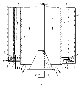
Figure 1 shows the adjusting apparatus of the invention in a concentrate
burner,
where the concentrate is fed into the burner via concentrate channels 1. The
number of concentrate channels can be one or several. Into the air chamber 2,
there is conducted some process gas, generally oxygen-enriched air via
conduits
3. The number of gas conduits 3 can also be one or several. The concentrate
burner is provided with a central jet distributor 4 and with a central oxygen
lance
5. The concentrate is discharged into the reaction space of the suspension
smelting fumace from a concentrate channel surrounding the central jet
distributor
via a concentrate discharge orifice 6. The oxygen-enriched air is discharged
through one annular air channel surrounding the concentrate channel via an air
discharge orifice 7. The adjusting apparatus according to the invention
comprises
an actuator 10 installed outside the burner, a drive axis with transmission 11
and
movable adjusting members 8 supported against the wall of the air channel. The
operation of the actuator can be controlled either manually or with remote
control.
2177121
The movement of the actuator is transformed, by means of a gear drive, into
rotary motion of the drive axis 10. The rotary motion of the drive axis 10 is
further
transmitted, by means of the gear drive, to rotary motion of the drive ring 9
installed around the air channel. Underneath the drive ring 9, the adjusting
members 8 provided in connection with the air channel, consist of several ring
sectors which are on one side articulated to the air channel, and on the
opposite
side articulated to the drive ring 9. The rotary motion of the drive ring 9
forces the
sides articulated to the drive ring 9 of the ring sectors 8 to shift towards
the air
channel, in which case the flow area in the flow channel of the reaction gas
is
reduced, so that the outer circumference of the reaction gas discharge orifice
remains essentially circular. A rotary motion of the drive ring 9 in the
opposite
direction forces the adjusting members 8 to shift away from the reaction gas
flow
channel, so that the flow area in the reaction gas flow channel increases, and
the
flow rate of the reaction gas slows down.
Point A of figure 2 illustrates a case where the adjusting members 8 are fully
open, and the reaction gas is discharged throughout the area of the flow
channel
12. Point B shows a case where the adjusting members 8 are in a position
throttling the transversal flow area of the reaction gas flow channel, so that
the
reaction gas is discharged along the free area of the reaction gas channel
only.
Figure 3 shows an example of a case where the desired flow rate in the opera-
tional area is 100 m/s 20 m/s. With the adjusting array according to the
inventi-
on, this operational area is achieved in the range 7,200 - 48,000 m3/h,
whereas it
would be only 32,000 - 48,000 m3/h with an unadjusted application. When
operating with remote control, the adjusting can be connected directly to a
process computer which adjusts the desired flow rate automatically, for
instance
when the amount of supplied solids changes.
2177121
6
In the above specification the apparatus of the invention is described with
referen-
ce to one preferred embodiment only, but it is naturally clear that the
invention can
be largely modified within the scope defined in the appended claims.