Note : Les descriptions sont présentées dans la langue officielle dans laquelle elles ont été soumises.
, 21 77~26
Docket # 44,630
FLUSHING MEANS WITH A TOILET BOWL
FIELD OF THE INVENTION
The present invention pertains to a flushing means with a toilet bowl,
which has a flushing channel in an upper edge and a siphon trap at an outlet
5 pipe, which siphon trap is connected to a suction siphon leading to a drain
pipe, and with a flushing device to release an amount of flushing water, a part
of which can be fed into the toilet bowl Vi?l the flushing channel and another
part to an outlet opening vi~ a connection pipe.
BACKGROUND OF THE INVENTION
To guarantee at least the following three conditions, approximately 9
2 1 77 1 26
L of water are needed for one flushing in the case of the prior-art flushing
means with a toilet bowl. First, the inner surface of the toilet bowl shall be
cleaned during each flushing. Second, the fecal matter shall be removed into
the drain pipe through the soil pipe of the toilet bowl. Third, the siphon trap
5 shall be completely refilled at the end of each flushing. If these conditions
were not regularly met, this would lead to unacceptable hygienic conditions
and to odor nuisance.
A flushing means of the above-mentioned class, which is said to
guarantee flushingwith less than 9 L of water, has become known in the state
of the art from WO 95/04196. Part of the amount of flushing water is fed in
this flushing means to the siphon trap via a so-called jet inlet. Similar means
have also become known from FR-A-2 241 664, DE-A-36 03 822 and EP-A-0
352 712. The latter document shows, especially in Figure 7, a flushing means
with a flushing tank, from which water can be fed to a jet inlet arranged in the
J lower area of the toilet bowl through a connection pipe branched off from the
flushing elbow.
SUMMARY AND OBJECTS OF THE INVENTION
The relatively high expense of lr~anufacture is considered to be a
disadvantage of the prior-art flushing means. The primary object of the
20 present invention is therefole to provide a flushing means of the class
described, which is characterized by a simpler design. This task is
2177126
accomplished in a means of this class by the connection pipe having a
hydraulic seal, which hydrau lically seals the connection pipe during the suction
process against a vacuum at the outlet opening. This makes it possible to feed
water directly to a nozzle or a jet inlet via the connection pipe. Mechanical
S valves in the connection pipe, whicll would have to prevent the connection
pipe from being suctioned empty during the suctioning of the toilet bowl, are
replaced in the [flushing] means according to the present invention by a
hydraulic seal, which can be produced in a very simple manner and also has
reduced susceptibility to the formation of lime deposits. Moreover, such a
10 hydraulic seal is highly reliable in operation and requires no maintenance and
cleaning.
According to another aspect of the present invention, the task is
accomplished by the connection pipe having, on the inlet side, an opening
which extends into a flushing elbow and through which opening water can be
fed directly from the top to the connection pipe as well as to a hydraulic seal
arranged therein. The water may be fed to the opening from, e.g., a fluslling
tank arranged above this opening at the necessary velocity of flow and under
a corresponding pressure. The velocity of flow of the water is hardly reduced
by the hydraulic seal, so that it can be released essentially without any loss of
20 energy with the necessary kinetic energy at the end of the connection pipe.
A simple yet reliable division of the flushing water is guaranteed if,
2 1 771 26
according to a variant of the present inven~ion, a flushing elbow has a
horizontal arm leading to the flushing channel and a vertical arm leading to
the flushing device, and the connection pipe opens into the flushing elbow
under the vertical arm. The water flowing from the flushing tank into the
S flushing elbow is IIOW taken up partially directly by the connection pipe. The
rest of the water flows into the flushing channel of the toilet bowl via the
horizontal arm. The division of the water can be set in a simple and reliable
manner by selecting the size of the opening of the connection pipe. Further
advantageous features become apparent from the dependent patent claims, the
following specification, as well as the drawing.
The various features of novelty which characterize the invention are
pointed out with particularity in the claims annexed to and forming a part of
this disclosure. For a better understanding of the invention, its operating
advantages and specific objects attained by its uses, reference is made to the
accompanying drawings and descriptive matter in which a preferred
embodiment of the invention is illustrated.
BRIEF DESCRIPTION OF THE DRAWINGS
In the drawings:
Figure 1 is a sectional view through a flushing means according to the
present invention;
Figure 2 is a section through part of the means according to Figure 1;
2177126
Figure 3 is a section along line III-III in Figure 2;
Figures 4 through 7 are schematic sectional views showing of the flushing
means according to the present invention during different phases
of a flushing process: and
Figure 8 is a partial view o~ the rear side of the means according to the
present invention.
DETAILED DESCRIPTION OF THE PREFERRED
EMBODIMENT
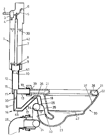
The flushing means shown schematically in Figure 1 has a toilet bowl
20 made of, e.g., ceramic~ wllich has, in the usual manner, a siphon trap 23
and, in an upper edge 3~, a bowl-flushing channel 21 with a plurality of
openings 22 directed toward the inside 37 of the toilet bowl 20. The bowl-
flushing channel 21is connected to a flushillg elbow 11 at a connection piece
39 projecting in the rearward direction on the rear side.
A suctionsiphon 24(knowll per se), which has an overflow edge 36 and
is connected to a drain pipe 26, is connected to a rearvardly and upwardly
directed end 40 of the siphon trap 23. The suction siphon 24 can be
recognized in Figure 8 from the rear side of the means. The suction siphon
24 causes the nushing water present in the siphon-trap 23 during the flushing
process to be suctioned into the sewer pipe 26, so that the toilet bowl 20 will
thus be extensively emptied.
2177126
The flushing elbow 11 is tightly connected to the bowl-flusl~ g cllallnel
21 by means of a gasket 19 on a horizontally extending arm 13. An upwardly
extending arm 12 of the flushing elbow 11 is also tightly connected to a
connection piece 41 of a flushing device 1. The flushing device 1 is a flushing
S tank in the exemplary embodiment shown. However, a design in which the
flushing device is designed differently, e.g., as a flushing valve, is conceivable
as well. The connection piece 41 has a downwardly directed opening 10 as
well as a valve seat 9, which cooperates with a valve disk 8 of a valve pipe 7.
To trigger a flushing, the valve pipe 7 is raised from the position shown by
10 means of, e.g., a pivotable lever 5 of an actuating means 6 in the known
manner. Flushing water 30 contained in a container 42 of the flushing device
1 is now released into the flushing elbow 11 through the opening 10 of the
connection piece 41. The flushing water 30, which is under the action of
gravity, then flows downward in the vertical alm 12. The emptied container
5 42 is refilled with a prior-art inlet valve 3 (known per se), which is connected
to a supply line 2, via an inlet line 43. In addition, water can be released into
the flushing elbow 11 through the interior of the valve pipe 7 via another inlet
pipe 4.
A connection pipe 14 opens into the flushing elbow 11 from below on
20 the inlet side and into a rising area 35 of the suction siphon 24 from the top
on the outlet side. At the end opening into the flushing elbow 11, the
2177126
connection pipe 14 is open ~t all upwardly directed opening 15 for directly
receiving water from the flushing elbow 11. As is shown especially clearly in
Figure 2, the opening 15 is located at the top end of a pipe section 43, which
extends upward to above the central axis 44 of the horizontal arln 13. The
5 pipe section 43 is the upper extension of a vertically extending filling pipe 16
and may be made, together with same, in one piece with the flushing elbow 11.
As can be seen, the opening 15 is substantially smaller than the cross section
of the vertical arm 12 of the flushing elbow 11.
The filling pipe 16 opens into an obliquely rising pipe 17 at the lower
10 end, in a relatively short horizontal area 45. This rising pipe 17 has an upper
overflow edge 36, after which an obliquely downwardly directed downpipe 1~
is connected to the pipe 14. This downpipe 18 opens with an opening 25 into
a rising area 35 of the suction siphon 24. If the connection pipe 14 is filled
with water 33 according to Figure 2, the connection pipe 14 forms a hydraulic
i seal with the pumping head H. This causes a counterpressure to build up in
the case of a vacuum in the opening 25 as the water column 33a in the rising
pipe 17 drops. The maximum counterpressure is determined by the height of
rise H indicated in Figure 2. The height H is selected to be such that the
maximum counterpressure is higher than a vacuum that is maximally
20 expectable at the opening 25. A vacuum at the opening 25 is gener~ted during
flushing by the water flowing past the opening 25 in the suction siphon 24.
21 771 26
This effect is Icnown per se.
The mode of action of the flushing means according to the present
invention will be explained in greater detail below on the basis of Figures 1
througll 7.
Figure 1 shows the device in the resting position, in which it is ready for
a flushing. The container 42 of the flushing device 1 is filled with, e.g., 9 L of
flushing water 30 in this position. The hydraulic seal of the connection pipe
14 is also filled with water 33 up to the overflow edge 36. Finally, the siphon
trap 23 is also filled with water 47, which forms a seal against the pipe 26, up
10 to the overflow edge 34 of the suction siphon 24. To trigger a flushing, the
actuating means 6 is actuated according to Figure 4 in the direction of the
arrow 29, and the valve pipe 7 is now raised, while the valve opening 9 is
opened and flushing water 30 flows through this opening downward into the
flushing elbow 11. Part of this downwardly flowing flushing water is sent into
S the toilet-flushing channel 21 via the horizontal arm 13 according to Figure 3
in the direction of the arrow 27 and, in the direction of the arrows 2g, to the
openings 22, where the flushing water flows hlto the toilet bowl 20 in the
direction of the arrows 32 (Figure 4). The remaining part of the flushing
water flows directly through the opening 15 into the connection pipe 14. The
20 percentage of this amount of water is determined by the relative size of the
opening 15. ~he water flowing into the connection pipe 14 flows, together
2l7~26
with the water already present in the connection pipe 14, with the exception
of a residual amount, into the suction siphon 24 through the opening 25 in the
direction of the arrow 31. The water flowing out of the opening 2S in the
downward direction brings about a backflow in the water already present in
S the siphon trap 23. As a result, the level of the water 47 present in the toilet
bowl 20 is raised, and its potential energy and consequently its flushing power
are thus increased. The inside 37 of the toilet bowl 20 is cleaned at the same
time via the bowl-flushing channel 21. The condition shown in Figure S is
reached after complete emptying of the flushing tank 1. As can be seen, the
level 48 of the water 47 is above the overflow edge 34 of the suction siphon
24. The water 47 present in the toilet bowl 20 and in the siphon trap 23 is
suctioned and delivered into the pipe 26 due to the action of the suction
siphon 24. Fecal matter is now entrained and also transported into the pipe
26. There is a vacuum inside the downpipe 18 during this suction process, but
S this vacuum is lower than the counterpressure maximally generated in the
rising pipe 17.
The suction process is completed when the toilet bowl 20 is emptied,
according to Figure 6, except for a residual amount of water 49. The flow in
the suction siphon 24 is now interrupted, and water present in the area 35
20 flows back into the siphon trap 23. To nnake the flushing device ready for
another flushing, water is introduced into the flushing elbow 11 through the
2 1 77 ~ 26
hollow valve pipe 7 via pipe 4 according to Figures 6 and 7, and this water
enters the connection pipe 14 and refills the siphon trap 23 up to the level of
the overflow edge 36. The siphon trap 23 may also be refilled via the bowl-
flushing channel 21. The amount of water released through the pipe 4 is
5 designed to be such that the starting position shown in Figure 7, in which the
flushing means is ready for another flushing, is eventually reached. The
container 42is refilled at the same time via the pipe 43 along with the refilling
of the toilet bowl 20. The device is thus ready for another flushing. It is
essential that the refilling of the toilet bowl 20 and the refilling of the
10 container 42 can take place in a relatively short time. As can be clearly
recognized from the above explanations, the opening 15 of the connection pipe
14 is continuously open during a flushing as well as during the refilling. No
valves or mechanical closing devices are necessary in the connection pipe 14.
Correspondingly, there is also no risk of malfunction of the seal in the
lS connection pipe 14 due to lime deposits. In addition, it is essential that the
space requirement for the hydraulic seal as well as for the flushing elbow 11
can be kept very small. Moreover, the pipe 14 as well as the flushing elbow
l l can be manufactured at a very low cost, e.g., as injection moldings.
While a specific embodiment of the invention has been shown and
20 described in detail to illustrate the application of the principles of the
invention, it will be understood that the invention may be embodied otherwise
2177126
without dep~rting from such principles