Note : Les descriptions sont présentées dans la langue officielle dans laquelle elles ont été soumises.
WO 95/15715 ~ ~ ~ pCT/US94/133~5
1
DEVICES AND METHODS FOR INTRAC RT1T~(~ DR(1f~~11TfRF
FIELD OF THE INVENTION
This invention relates generally to instruments and
techniques for performing less-invasive surgical
procedures, and more specifically, to instruments and
techniques for less-invasive surgery within the heart and
great vessels.
BACKGROUND OF THE INVENTION
Various types of surgical procedures are currently
performed to investigate, diagnose, and treat diseases of
the heart and the great vessels of the thorax. Such
procedures include repair and replacement of mitral,
aortic, and other heart valves, repair of atrial and
ventricular septal defects, pulmonary thrombectomy,
treatment of aneurysms, electrophysiological mapping and
ablation of the myocardium, and other procedures in which
interventional devices are introduced into the interior
of the heart or a great vessel.
Using current techniques, many of these procedures
require a gross thoracotomy, usually in the form of a
median starnotomy, to gain access into the patient's
thoracic cavity. A saw or other cutting instrument is
used to cut the sternum longitudinally, allowing two
opposing halves of the anterior or ventral portion of the
rib cage to be spread apart. A large opening into the
thoracic cavity is thus created, through which the
SUBSTITUTE SHEET (RULE 26)
WO 95/15715 PCTIUS94113305
2
surgical team may directly visualize and operate upon the
heart and other thoracic contents.
Surgical intervention within the heart generally
requires isolation of the heart and coronary blood
vessels from the remainder of the arterial system, and
arrest of cardiac function. Usually, the heart is
isolated from the arterial system by introducing an
external aortic cross-clamp through a sternotomy and
applying it-to the aorta between the brachiocephalic
artery and the coronary ostia. Cardioplegic fluid is
then injected into the coronary arteries, either directly
into the coronary ostia or through a puncture in the
aortic root, so as to arrest cardiac function. In some
cases, cardioplegic fluid is injected into the coronary
sinus for retrograde perfusion of the myocardium. The
patient is placed on cardiopulmonary bypass to maintain
peripheral circulation of oxygenated blood.
Of particular interest to the present invention are
intracardiac procedures for surgical treatment of heart
valves, especially the mitral and aortic valves.
According to recent estimates, more than 79,000 patients
are diagnosed with aortic and mitral valve disease in
U.S. hospitals each year. More than 49,000 mitral valve
or aortic valve replacement procedures are performed -
annually in the U.S., along with a significant number of
heart valve repair procedures. -
Various surgical techniques may be used to repair a
diseased or damaged valve, including annuloplasty
(contracting the valve annulus), quadrangular resection
(narrowing the valve leaflets), commissurotomy (cutting
the valve commissures to separate the valve leaflets),
shortening mitral or tricuspid valve chordae tendonae,
reattachment of severed mitral or tricuspid valve chordae
tendonae or papillary muscle tissue, and decalcification
of valve and annulus tissue. Alternatively, the valve
may be replaced, by excising the valve leaflets of the
natural valve, and securing a replacement valve in the
SUBSTITUTE SHEET (RULE 26)
CA 02177490 2005-07-22
3
valve position, usually by suturing the replacement valve
to the natural valve annulus. Various types of
replacement valves are in current use, including
mechanical and biological prostheses, homografts, and
allografts, as described in Bodnar and Frater,
Replacement Cardiac Valves 1-357 (1991),
A comprehensive
discussion of heart valve diseases and the surgical
treatment thereof is found in Kirklin and Barratt-Boyes,
Cardiac Surgery 323-459 (1986),
The mitral valve, located between the left atrium
and left ventricle of the heart, is most easily reached
through the wall of the left atrium, which normally
resides on the posterior side of the heart, opposite the
side of the heart that is exposed by a median sternotomy.
Therefore, to access the mitral valve via a sternotomy,
the heart is rotated to bring the left atrium into an
anterior position accessible through the sternotomy. An
opening, or atriotomy, is then made in the right side of
the left atrium, anterior to the right pulmonary veins.
The atriotomy is retracted by means of sutures or a
retraction device, exposing the mitral valve directly
posterior to the atriotomy. One of the forementioned
techniques may then be used to repair or replace the
valve.
An alternative technique for mitral valve access may
be used when a median sternotomy and/or rotational
manipulation of the heart are undesirable. In this
technique, a large incision is made in the right lateral
side of the chest, usually in the region of the fifth
intercostal space. One or more ribs may be removed from
the patient, and other ribs near the incision are
retracted outward to create a large opening into the
thoracic cavity. The left atrium is then exposed on the
posterior side of the heart, and an atriotomy is formed
W0 95115715 PCTlUS94/13305
21'~'~~~~
4
in the wall- of the left atrium, through which the mitral
valve may be accessed for repair or replacement.
Using such open-chest techniques, the large opening
provided by a median sternotomy or right thoracotomy '
enables the surgeon to see the mitral valve directly
through the left atriotomy, and to position his or her '
hands within the thoracic cavity in close proximity to
the exterior of the heart for manipulation of surgical
instruments, removal of excised tissue, and/or
introduction of a replacement valve through the atriotomy
for attachment within the heart. However, these
invasive, open-chest procedures produce a high degree of
trauma, a significant risk of complications, an extended
hospital stay, and a painful recovery period for the
patient. Moreover, while heart valve surgery produces
beneficial results for many patients, numerous others who
might benefit from such surgery are unable or unwilling
to undergo the trauma and risks of current techniques.
What is needed, therefore, are devices and methods
for carrying out heart valve repair and replacement as
well as other procedures within the heart and great
vessels that reduce the trauma, risks, recovery time and
pain that accompany current techniques. The devices and
methods should facilitate surgical intervention within
the heart or great vessels without the need for a gross
thoracotomy, preferably through small incisions within
intercostal spaces of the rib cage, without cutting,
removing, or significantly deflecting the patient s ribs
or sternum. In particular, the devices and methods
should allow for removal of tissue from the thoracic
cavity, as well as for introduction of surgical
instruments, visualization devices, replacement valves
and the like into the thoracic cavity, to facilitate '
heart valve repair and replacement. Preferably, the
- devices and methods should facilitate replacement of a '
heart valve with various types of prostheses, including
SUBSTiTU T E SHEET (RULE 26}
WO 95115715 ~ ~ PCTlUS94/13305
mechanical and biological prostheses, homografts, and
allografts.
' SUMMARY OF THE INVENTION
The invention provides devices and methods for
~ 5 performing less-invasive surgical procedures within an
organ or vessel, and particularly, within the heart and
great vessels of the thoracic cavity. The devices and
methods of the invention facilitate intervention within
the heart or great vessels without the need for a median
sternotomy or other form of gross thoracotomy,
substantially reducing trauma, risk of complication,
recovery time, and pain for the patient. Using the
devices and methods of the invention, surgical procedures
may be performed through percutaneous penetrations within
intercostal spaces of the patient's rib cage, without
cutting, removing, or significantly displacing any of the
patient's ribs or sternum. The devices and methods are
particularly well-adapted for heart valve repair and
replacement, Facilitating visualization within the
patient's thoracic cavity, repair or removal of the
patient's natural valve, and, if necessary, attachment of
a replacement valve in the natural valve position. The
invention facilitates valve replacement with any of a
variety of commercially-available replacement valves,
including mechanical prostheses, bioprostheses,
homografts, and allografts.
In a first preferred embodiment, the invention
provides a method of closed-chest surgical intervention
within an internal cavity of the patient's heart or great
vessel. Utilizing the method of the invention, the
patient's heart is arrested and cardiopulmonary bypass is
' established. An internal portion of the patient's chest
is viewed by means of a scope extending through a
percutaneous intercostal penetration in the patient's
chest. A cutting means-is introduced through a
percutaneous intercostal penetration in the patient's
SUBSTITUTE SHEET (RULE 26)
W095115715 " , PCT/US94113305
6
chest, and the cutting means is used to form an internal
penetration in a wall of the heart or great vessel. An
interventional tool is then introduced through a
percutaneous intercostal penetration and through the '
internal penetration in the heart or great vessel to
perform a surgical procedure within the internal cavity
under visualization by means of the scope. One or more
percutaneous cannulae may be positioned within an
intercostal space of the chest-wall through which the
interventional tool may be introduced into the chest
cavity. The surgical procedures which may be performed
within the heart or great vessel include repair or
replacement of heart valves, repair of atrial and
ventricular septal defects, pulmonary thrombectomy,
treatment of aneurysms, electrophysiological mapping and
ablation of the myocardium, myocardial drilling,
correction of congenital defects, coronary artery bypass
grafting, and other procedures.
The patient's heart is preferably arrested by
occluding the patient's aorta between the patient's
coronary arteries and the patient's brachiocephalic
artery with an expandable member on a distal end of an
endovascular catheter. Cardioplegic fluid is then
introduced through a lumen in the catheter into the
patient's aorta upstream of the expandable member to
arrest cardiac function. Alternatively, or in addition
to such antegrade cardioplegic fluid delivery,
cardioplegic fluid may be delivered in a retrograde
manner by means of a catheter.pasitioned in the coronary
3o sinus of the patient's heart. In an alternative
approach, an external cross-clamp may be placed
thoracoscopically on the aorta through a small incision
or cannula in the patient's chest. Cardioplegic fluid '
may be delivered through either a thoracoscopically
introduced cannula or an endovascular catheter extending '
into the ascending aorta upstream of the cross-clamp.
SUSST('~UTE SHEET (RUBS 26)
WO 95/15715 2 ~ ~ ~ ~ {~ ~ PCT/US94113305
In a preferred embodiment, the surgical procedure
comprises surgically treating a heart valve. Such
surgical treatment may involve repairing the valve by
introducing instruments through an intercostal
penetration and through the internal penetration in the
heart to perform, for example, annuloplasty, quadrangular
resection of valve leaflets, commissurotomy, reattachment
of chordae tendonae or papillary muscle tissue,
shortening of chordae tendonae, decalcification, and the
like.
The heart valve may also be replaced with a
replacement valve. In this embodiment, the method may
further comprise the step of removing all or part of the
patient's natural heart-valve by means of a cutting tool
introduced through a percutaneous intercostal penetration
and through the internal penetration in the heart. The
method further comprises the step of introducing a
replacement valve through a percutaneous intercostal
penetration and through the internal penetration into the
internal cavity within the heart. The replacement valve
is then fastened within the heart, usually by means of an
instrument introduced through a percutaneous intercostal
penetration and through the internal penetration in the
heart wall.
The method may further include the step of sizing
the patient's heart valve before the replacement valve is
introduced. In an exemplary embodiment; a sizing
instrument is introduced through a percutaneous
intercostal penetration and through the internal
penetration in the heart to measure the size of the valve
annulus and to determine the size of the replacement
valve.
' The replacement valve may be fastened in position in
various ways, including suturing the replacement valve to
' 35 an annulus at the natural valve position in the heart.
In one embodiment, the sutures are applied to the annulus
at the valve position, drawn out of the patient's body
SUBSTITUTE SHEET (RULE 26}
W 0 95115715 PCT/US94113305
.. ,,
:' ,
8
through the internal penetration and through a
percutaneous intercostal penetration, and then applied to
the replacement valve. The sutures may further be
radially arranged in spaced-apart-locations about an
organizer ring disposed outside of the patient's body.
The sutures are then held in tension as the replacement '
valve is introduced into the interior of the heart and
positioned in the natural valve position. The
replacement valve may be introduced by means of a valve
l0 holder attached to an elongated handle, or simply pushed
along the sutures by means of the surgeon's hands or
conventional tools such as forceps or needle drivers.
In a particular preferred-embodiment, the heart
valve comprises a mitral valve which is disposed between
the left atrium and left ventricle of the patient's
heart. A percutaneous penetration is made within an
intercostal space in a right lateral portion of the
patient's chest, usually within the fourth, fifth, or
sixth intercostal space. From this penetration, an
internal penetration may be formed in the wall of the
left atrium at a location which is in a generally
straight line drawn from the penetration in the right
lateral portion of the chest to the patient's mitral
valve. In this way, surgical instruments may be
introduced from the penetration in the right chest to
form the internal penetration in the heart wall, repair
or excise the patient's natural valve, and introduce and
attach a replacement valve.
In a further aspect of the invention, a prosthesis
assembly is provided for closed-chest replacement of a
heart valve. The prosthesis assembly comprises a
replacement valve having an annular attachment portion
and a movable valve portion coupled to the attachment '
portion. The prosthesis assembly further includes holder
means releasably mounted to the attachment portion, '
wherein the holder means is configured to allow
SUBSTITUTE SHEET (RULE 26)
WO 95115715 ~ ~ ~ PCT/I1S94/13305,
9
introduction of the replacement valve through an
intercostal space in the patient's chest.
In a preferred embodiment,--the replacement valve and
' the holder means together have a profile with a width
which is less than the width of the intercostal space.
Preferably, the intercostal space is less than about 20
mm in width. The attachment portion of the replacement
valve will usually have an outer diameter which is
greater than the intercostal width.
The holder means of the device preferably comprises
an elongated handle having a distal end mounted to the
replacement valve and a proximal end opposite the distal
end. The handle is configured to introduce the
replacement valve into the patient's heart through the
intercostal space. Preferably, the handle is at least
about 20 cm in length to allow positioning the
replacement valve in the heart from a right lateral
portion of the patient's chest. The handle may further
include means for releasing the replacement valve, the
releasing means being configured for actuation from the
proximal end of the handle.
The handle may also include means for pivoting the
replacement valve from a first orientation for
introduction through the intercostal space to a second
orientation for attachment in the patient's heart. The
pivoting means is configured for actuation from a
proximal end of the handle. In this way, the replacement
valve may be introduced edge-first through the
intercostal space, then pivoted about an axis generally
perpendicular to the handle into an orientation suitable
for attachment within the patient's heart.
Alternatively, the valve prosthesis may be collapsible or
' compressible to permit introduction through an
intercostal space into the thoracic cavity.
Preferably, the replacement valve is premounted to
the holder means and the two are sterilized and packaged
together in a sterile pack. In this way, the pack may be
SUBSTITUTE SHEET (RULE 26}
WO 95/15715 PCTIITS94/13305
21'~'~ 4~ ~
opened in the sterile operating room environment with the
valve and holder ready for immediate surgical use.
In a further embodiment, the invention provides a
thoracoscopic device for placement of a replacement valve
5 in a valve position of a patient's heart.- In a preferred
embodiment, the thoracascopic device comprises an '
elongated handle configured for-positioning through an
intercostal space in the patient's chest, as described
above. The device includes means at a distal end of the
10 handle for releasably holding a replacement valve in an
orientation for introduction through the intercostal
space, and may further include means for pivoting the
replacement valve relative to the handle from a first
orientation for introduction through the intercostal
space, to a second orientation for placement in the valve
position. The thoracoscopic device further includes, in
a preferred embodiment, means at the proximal end of the
handle for releasing the replacement valve from the
holding means once the prosthesis has been positioned and
secured within the heart. -
In a further aspect of the invention, a percutaneous
access cannula is provided to-=facilitate closed-chest
replacement of a heart valve in a patient's heart. The
access cannula comprises a cannula body configured for
placement in an intercostal space in the patient's chest,
the cannula having a distal end, a proximal end, and a
lumen extending therebetween. The lumen is configured to
allow passage of a-replacement valve therethrough. An
obturator is positionable in the lumen to facilitate
introduction of the cannula body. The obturator has a
cross-sectional width that is equal to or less than the
width of the intercostal space, and a cross-sectional
height that is greater than the cross-sectional width. '
The replacement valve has an annular attachment
portion with an outer diameter, and the obturator as well
as the lumen in the cannula have a cross-sectional height
at least equal to the.outer diameter, allowing the
SUBSTITU T E SHEET RULE 26)
WO 95!15715 ~ PCTlUS94/13305
r
11
replacement valve to be introduced
through the .lumen of
the cannula. In one embodiment, the
cross-sectional
height of the lumen in the cannula
is about two to six
times the cross-sectional width.
The lumen and obturator
may have a rectangular cross-section,
oval cross-section,
or other shape. The cannula body
may be rigid or
deformable, while the obturator is
usually rigid to
facilitate introduction.
The access cannula may further be
provided with
suture retaining means on its proximal
end configured to
retain a plurality of sutures in
a spaced-apart
relationship. The suture retaining
means may have
various configurations, such as a
plurality of slots in a
proximal end of the cannula body
in circumferentially
spaced positions around the lumen.
The slots in the
access cannula may further include
means such as slitted,
elastomeric inserts, for frictionally
engaging the
sutures to maintain tension thereon
while the prosthesis
is introduced into the heart.
A second organizing ring may also
be provided in a
position spaced-apart from the access
cannula outside of
the patient's body. The second organizing
ring has an
interior passage through which the
sutures may extend and
a plurality of means circumferentially
spaced around the
passage for frictionally engaging
the sutures. In this
way, sutures may be applied to the
valve annulus in the
patient's heart, drawn through the
lumen in the cannula
and retained in the suture organizing
means on the access
cannula's proximal end. The sutures
may then be applied
to the replacement-valve and retained
in the second
organizing ring. Once all of the
sutures have been
applied to the prosthesis, the prosthesis
may be
' introduced into the heart by sliding
it along the
sutures, which are held in tension
by the second
organizing ring. Alternatively, the
sutures may be held
in tension by individual clamps,
tape,
commercially-available suture organizers,
or other means
SUBSTITUTE SHEET (RULE26)
WO 95II5715 PCTIUS94113305
~17'~~9b
12
for exerting traction on the free ends of each individual
suture.
The invention further provides a system for
closed-chest replacement of a heart valve in a patient's '
heart. The system includes means for forming a'~
percutaneous intercostal penetration in the patient's "
chest, and a visualization scope configured to pass
through an intercostal space in the patient's chest for
viewing an internal chest cavity. Means are also
provided for arresting the patient's heart from a
location outside of the chest cavity. A cardiopulmonary
bypass system, including means for delivering oxygenated
blood to the patient's arterial system, is provided for
maintaining peripheral circulation of oxygenated blood.
Cutting means positionable through a percutaneous
intercostal penetration into the chest cavity are
provided for forming an internal penetration in a wall of
the patient's heart or great vessel. The system further
provides interventional means positionable through a
percutaneous intercostal penetration and through the
internal penetration for performing a surgical procedure
within the heart or great vessel.
In a preferred embodiment, the means for arresting
the heart comprises an endovascular catheter having
expandable means near its distal end for occluding the
patient's ascending aorta between the patient's coronary
arteries and the patient's brachiocephalic artery. The
catheter further includes an internal lumen for
delivering cardioplegic fluid into the aorta upstream of
the expandable means to perfuse the myocardium through
the coronary arteries.
The interventional means preferably comprises means
for securing a replacement valve in a valve position '
within the patient's heart. Usually, the replacement
valve securing means comprises an elongated handle like '
that described above, having means at its distal end for
releasably holding a replacement valve. The handle may
SUBSTITUTE SHEET (MULE 26~
W 0 95115715 PCT/US94/13305
13
also facilitate pivoting the replacement valve for
introduction through an intercosta-1 space.
Preferably, the system also includes at least one
cannula positionable in a percutaneous intercostal
penetration, through which surgical instruments or a
~ replacement valve may be introduced into the thoracic
cavity. The cannula may have a lumen with a
cross-sectional height greater than its width to allow
edge-first introduction of a replacement valve that has
an outer diameter larger than the interoostal space, as
described above.
The system may further include cutting means
positionable through a percutaneous intercostal
penetration and through the internal penetration in the
patient's heart for removing at least a portion of the
patient's heart valve. The cutting means for removing
the heart valve may comprise scissors, retractable knife,
biters, or the like.
The system preferably includes means positionable
through a percutaneous intercostal penetration and
through the internal penetration for sizing an annulus of
the patient's heart valve. In one embodiment, the sizing
means comprises an elongated shaft and a plurality of
interchangeable sizing disks of various sizes attachable
to a distal end of the shaft. The shaft and sizing disk
may be introduced through a percutaneous intercostal
penetration and through the internal penetration to
position the sizing disk adjacent to the annulus of the
patient's heart valve, allowing a -comparison of the
annulus diameter to the disk diameter. The sizing disk
may be pivotable relative to the shaft to allow
introduction into the thoracic cavity through an
intercostal space. Alternative means for sizing may also
be used, such as expandable baskets, balloons, endoscopic
~ 35 or endovascular visualization, fluoroscopy, or
transesophageal echocardiography.
SUBSTITUTE SHEET (RULE 26~
WO 95115715 , PCT/US94113305
s
.. ,
14
The system may further include means for attaching
the replacement valve to the patient's heart; which
comprises, in one embodiment, means for suturing the
replacement valve to a valve annulus in the patient's
heart. The system preferably includes organizing means
for maintaining the sutures in spaced-apart positions
outside of the chest cavity after the sutures have been
applied to the valve annulus within the heart. - The
organizing means is preferably fixed-to a proximal end of
a cannula disposed in a percutaneous intercostal
penetration, as described above. In this way, the
sutures may be applied to the natural valve annulus
within the patient's heart, drawn out of the chest cavity
through the cannu~a lumen, and positioned in spaced-apart
positions about the circumference of the proximal end of
the cannula. Means may also be provided for maintaining
tension on the ends of the sutures after they have been
applied to the replacement valve. This facilitates
advancing the replacement valve along the sutures,
through the lumen in the cannula, and into the chest
cavity.
The system may further include retraction means
positionable through an intercostal space in the
patient's chest for opening the internal penetration in
the wall of the heart or great-vessel. The retraction
means may comprise a collapsible rake, tethered clamp,
retraction sutures, or the like.
A further understanding of the nature and advantages
of the invention may be realized by reference to the
remaining portions of the specification and the drawings.
BRIEF DE&CRIPTION OF THE DRAWINGS
Figure 1 is a perspective view of a system for
closed-chest mitral valve replacement constructed in
accordance with the principles of the present invention,
showing the use of the system in a patient.
SUBSTITUTE SHEET (RULE 26~
WO 95115715 ~ PCTlUS94II3305
.
Figure 2 is a front view of the system of Figure 1,
showing the positioning of the system in the patient's
chest.
Figure 3 is a front view of a patient's
5 cardiovascular system illustrating the positioning of a
system for arresting the heart and establishing
cardiopulmonary bypass in accordance with the principles
of the present invention.
Figure 4 is a top view looking into the patient's
10 thoracic cavity through a passage of an access cannula in
the system of Figure 1, showing the creation of an
atriotomy in the patient's left atrium.
Figure 5 is a top view looking into the patient's
thoracic cavity through a passage of an access cannula in
15 the system of Figure 1, showing the removal of the mitral
valve leaflets.
Figure 6 is a top view looking into the patient's
thoracic cavity through a passage of an access cannula in
the system of Figure 1, showing the application of
sutures to the mitral valve annulus.
Figure 7 is a perspective view of the system of
Figure 1 positioned in the patient, showing the
application of sutures to a replacement valve.
Figures 8A-8B are transverse cross-sectional views
of the system and patient of Figure 1 taken through the
patient's thorax, showing the introduction of the
replacement valve into the left atrium and the tying of
knots in the sutures to secure the prosthesis in the
patient's heart.
Figure 9 is a top view looking into the patient's
thoracic cavity through a passage of an access cannula in
the system of Figure 1, showing pushing the knots toward
the replacement valve and trimming the free ends of the
sutures.
Figure l0 is a top view looking into the patient's
thoracic cavity through a passage of an access cannula in
SUBSTITUTE SHEET (RULE 26)
WO 95115715 ' , PCTIUS94113305
2 ~'~'~ 49 ~ ' _
16
the system of Figure'1, showing the closure of the
patient's left atrium.
Figures 11A-11C are perspective, front, and top
views respectively of the access cannula in the system of
Figure 1.
Figure 11D is a partial cut-away view taken along
line 11D-11D in Figure 11C.
Figure 12A is a side view of angled scissors in the
system of Figure 1. -
Figures 12B-12D are side views of a distal portion
of the scissors of Figure 12A showing alternative
embodiments thereof.
Figure 13 is a side view of a retractable knife in
the system of Figure.l. -
Figures 14A-14B are side and top views,
respectively, of grasping forceps in the system of Figure
1.
Figure 15 is a perspective view of a left atrial
retractor in the system of Figure 1.
Figures 16A-16B are side and top views,
respectively, of needle drivers in the system of Figure
1.
Figures 17A-17B are top and side views,
respectively, of a replacement-valve in the system of
Figure 1.
Figure 17C is an end view -of the replacement valve
of Figures 17A-17B positioned in a passage of an access
cannula in the system of Figure 1.
Figure 18 is a perspective view of a prosthesis
introducer in the system of Figure 1.
Figure 19A-is a side view of the prosthesis
introducer of Figure 18.
Figures 19B-19C are bottom and side views,
respectively, of a distal portion of the prosthesis
introducer of Figure 18.
SUSSTfTUTE SHEET (RULE 26}
W0 95/15715 PCT/US94/13305
17
Figures-19D-19E are top and side views,
respectively, of a stationary arm of the prosthesis
introducerof Figure 18.
Figures 19F-19G are top and side views,
respectively, of a movable arm of the prosthesis
introduces of Figure 18.
Figure 20A is a side partial cut-away view of the
prosthesis introduces of Figure 18.
Figure 20B is a top partial-cut-away view of a
distal portion of the prosthesis introduces of Figure 18.
Figure 21 is a perspective view of a sizing disk in
the system of Figure 1, positioned on the introduces of
Figure 18.
Figures 22, 23A and 23B are top and side views,
respectively, of the sizing disk of Figure 21.
Figures 23A-23B are top and side views,
respectively, of the sizing disk of Figure 21.
Figures 24A-24C are front, top, and side views,
respectively of a suture organizing ring in the system of
Figure 1.
Figures 25A-25B are side and top views, respectively
of a knot-pushing device in the system of Figure 1.
DETAILED DESCRIPTION OF SPECIFIC EMBODIMENTS
The invention provides methods and devices for
performing surgical interventions within the heart or a
great vessel such as the aorta, superior vena cava,
inferior vena cava, pulmonary artery, pulmonary vein,
coronary arteries, and coronary veins, among other
vessels. While the specific embodiments of the invention
described herein will refer to mitral valve repair and
replacement, it should be understood that the invention
will be useful in performing a great variety of surgical
procedures, including repair and replacement of aortic,
tricuspid, or pulmonary valves, repair of atrial and
ventricular septal defects, pulmonary thrombectomy,
removal of atrial myxoma, patent foramen ovale closure,
SUB~TIT~f T ~ S~~~T ~R~~.~ "c6)
WO 95115715 PCfIUS94113305
2 ~.'~'~ 4 g ~
treatment of aneurysms, electrophysiological mapping and
ablation of the myocardium, myocardial drilling, coronary
artery bypass grafting, angioplasty, atherectomy,
correction of congenital defects, and other procedures in
which interventional devices are introduced into the
interior of the heart, coronary arteries, or great
vessels. Advantageously, the invention facilitates the
performance of such procedures through percutaneous
penetrations within intercostal spaces of the rib cage,
obviating the need for a median sternotomy or other form
of gross thoracotomy.
The terms "percutaneous intercostal penetration" and
"intercostal penetration" as used herein refer to a
penetration, in the form or a small cut, incision, hole,
cannula, trocar sleeve, or the like, through the chest
wall between two adjacent ribs, wherein the patient's rib
cage and sternum remain substantially intact, without
cutting, removing, or significantly displacing the ribs
or sternum. These terms are intended to distinguish a
gross thoracotomy such as a median sternotomy, wherein
the sternum and/or one or more-ribs are cut or removed
from the rib cage, or one or more ribs are retracted
significantly, to create a large opening into the
thoracic cavity. A "percutaneous intercostal
penetration" may abut or overlap the adjacent ribs
between which it is-formed, but the maximum width of the
penetration which is available for introduction of
instruments, prostheses and the like into the thoracic
cavity will be the width of the intercostal space,
bounded by two adjacent ribs in their natural,
substantially undeflected positions. It should be
understood that one or-more ribs may be retracted or
deflected a small amount without departing from the scope
of the invention; however, the invention specifically
seeks to avoid the pain, trauma, and complications which
result from the large deflection or cutting of the ribs
in conventional, open-chest techniques.
SUBSTITUTE SHEET (RULE 26)
W0 95115715 PC'fIUS94113305
19
A first preferred-embodiment of a system and method
of closed-chest mitral valve replacement according to the
invention will be described with reference to Figures
1-10.- Figure 1 illustrates a system 20 for closed-chest
valve replacement positioned in a patient P on an
operating table T. Preferably, a wedge or block W having
a top surface angled at approximately 20' to 45' is
positioned under the right side of patient P so that the
right side of the patient's body is somewhat higher than
the left side. The patient's right arm A is-allowed to
rotate downward to rest on table T, exposing the right
lateral side of the patient's chest.
The valve replacement system 20 includes an access
cannula 22 positioned percutaneously within an
intercostal space between two ribs (shown in phantom) in
a right lateral side of the patient's chest. Additional
thoracoscopic trocar sleeves 24 of conventional
construction are positioned within intercostal spaces in
the right lateral chest inferior and superior to access
cannula 22, as well as in the right anterior (or ventral)
portion of the chest. An endoscope 25 of conventional
construction is positioned through a percutaneous
intercostal penetration into the patient's chest, usually
through one of trocar sleeves 24. The distal end of
endoscope 25 (shown in phantom) is preferably configured
to view at an angle between about 30' and 90° relative to
the shaft of endoscope 25, to facilitate visualization of
the heart from the right portion of the thoracic cavity.
A light source (not shown) is also provided on endoscope
25 to illuminate the thoracic cavity. A video camera 26
is mounted to the proximal end of endoscope 25, and is
connected to a video monitor 28 for viewing the interior
of the thoracic cavity. A first suture organizing ring
30 is mounted to a proximal end of access cannula 22. A
second organizing ring 32 is mounted to a support stand
34 fixed to table T. A replacement valve 36 is held at
the distal end of an introduces 38 between first
SUBSTITUTE SHED' (RU~.E 26)
W0 95115715 PCTIUS94/13305
organizing ring 30 and second organizing ring 32.
Introducer 38 extends through second organizing ring 32
and is supported by support stand,.34. Additional
instruments to be used in a procedure such as a retractor
5 40, as well as cutting, sut~iring, stapling, aspirating,
irrigating and other devices, may be introduced through
access cannula 22, trocar sleeves 24, and/or small,
percutaneous incisions within intercostal spaces of the
rib cage.
to Referring now to Figure 2, access cannula 22 is
positioned within an intercostal space I in the right
lateral side of the chest,- preferably in the third,
fourth, fifth, or sixth intercostal space between
adjacent ribs R. Additional trocar sleeves 24A, 24B are
15 positioned within intercostal spaces superior and
inferior to access cannula 22 in the right lateral side
of the chest. Access cannula 22 and trocar sleeves 24A,
24B are positioned so that instruments 42 introduced
through them may be directed toward the right side of the
20 left atrium of the heart H. A trocar sleeve 24C is
positioned in an intercostal space in the right anterior
side of the chest such that endoscope 25 may be
introduced to view the thoracic cavity and heart H
without interfering with instruments introduced through
access cannula 22 or trocar sleeves 24A, 24B. An
additional trocar sleeve 24D is positioned in an
intercostal space in the anterior side of the chest just
to the right of the sternum and anterior to the right
lateral side of the heart H.
It will be understood to those of ordinary skill in
the art that, in some cases, it may desirable to
eliminate some or all of trocar-sleeves 24 ahd/or access
cannula 22, and introduce instruments directly through
small, percutaneous intercostal incisions in the chest.
Advantageously, unlike laparoscopic, arthroscopic, and
other endoscopic procedures, no distension of the chest
is required using the method of the invention, so that
SUBST~ ~ UTE SHEET (RULE 26)
W0 95/15715 PCT/C1S94/13305
2~~~4~~
21
leakage of distension fluid through percutaneous
penetrations is not of concern. Thus, either
thoracoscopic trocar sleeves without fluid seals or
percutaneous incisions may be utilized for instrument
introduction into the thoracic cavity. Trocar sleeves
are generally preferred, however, in order to provide an
open passage into the thoracic cavity, to protect
adjacent tissue from injury resulting from contact with
instruments, and to avoid damaging instruments,
endoscopes, replacement valves, and the like when
introduced into the thoracic cavity.
Referring now to Figures 11A-11D, access cannula 22
will be described in greater detail. Access cannula 22
comprises a body 44 having a proximal end 46, a distal
end 48, and a passage 50 extending therebetween. Body 44
is configured to fit within an intercostal space I
without significant deflection of-adjacent ribs R,
usually having a width of less than about 20 mm. Passage
50 is configured to facilitate passage of replacement
valve 36 therethrough. Replacement valve 36 may have a
variety of configurations, but must have a diameter at
least equal to that of the patient's natural heart valve,
a diameter which commonly exceeds the width of the
intercostal spaces in the rib cage. Therefore, in order
to avoid cutting or retracting the patient's ribs,
replacement valve 36 is introduced edge-first through
passage 50 of access cannula 22, as described more fully
below. To accommodate such introduction of replacement
valve 36, passage 50 usually has a cross-sectional width
w of about 12 mm to 20 mm, and a cross-sectional height h
that is somewhat greater than cross-sectional width w,
usually 2-6 times cross-sectional width w, and preferably
in the range of 25 mm to 50 mm. Passage 50 may have
various cross-sectional shapes, including oval,
rectangular, race-track, and the like. This accommodates
a variety of replacement heart valves, including
mechanical and biological prostheses, as well as
SUBSTITUTE S~iEET (RULE 26~
R'O 95/15715 , PCTIUS94/83305
22
homograft and allograft tissue valves. It will be
understood, however, that certain replacement valves may
be collapsible or sufficiently small in size so that
passage 50 in access cannula 22 may have a round or
square cross-section and still allow passage of the
replacement valve therethrough. However, a
cross-sectional shape in which the height is greater than
the width may still be advantageous to allow greater
freedom of movement in manipulating the replacement valve
and other instruments introduced through passage 50.
As shown in Figure 11B, an obturator 52 is
positionable in passage 50 to facilitate introduction of
access cannula 22 through the chest-wall. Obturator 52
has a tapered distal end 54, a proximal end 56, and a rim
58 near proximal end 5b for engaging proximal end 46 of
cannula body 44. Usually, obturator 52 is positioned in
passage 50 of access cannula 22, and the two are
introduced through a small incision formed in an
intercostal space in the chest wall_ Obturator 52 is
then removed from passage 50.
As described briefly above, access cannula 22 may
further include a suture organizing ring 30 mounted to
its proximal end 46. Suture organizing ring 3o has a
ring-shaped body 60 and a plurality of slots 62
circumferentially spaced about-body 60. Usually, between
16 and 32 of slots 62 are provided, depending upon the
type of replacement valve and suturing technique to be
utilized in the procedure. An elastomeric retaining ring
64 is disposed in a circumferential channel in ring body
60, and has a plurality of slits 66, best seen in Figure
ilD, aligned with each slot 62. Slits 66 are provided
with chamfers 68 along the top surface of retaining ring
64 to facilitate positioning sutures within slits 66 for
retention therein. The function of suture organizing
ring 30 will-be described in greater detail below.
Referring again to Figure 2, once access cannula 22
and trocar sleeves 24 have been positioned in the
SUBSTITUTE SHEET RULE 26}
CA 02177490 2005-07-22
23
patient's chest, endoscope 25 is introduced through
trocar sleeve 24D and camera 26 is connected to video
monitor 28 (Figure 1). Endoscope 25 is manipulated so as
to provide a view of the right side of the heart, and
particularly, a right side view of the left atrium.
Usually, an endoscope of the type having an articulated
distal end, or a distal end disposed at an angle between
30' and 90' will be used, which is commercially
available from, for example, Olympus Corp., Medical
Instruments Division, Lake Success, NY.
At this point in the procedure, if not previously
accomplished, the patient is placed on cardiopulmonary
bypass (CPB), the patient's right lung is at least
partially collapsed, and the patient's heart is arrested.
Suitable techniques for arresting cardiac function and
establishing CPB without a thoracotomy are known.
As illustrated in Figure 3, CPB is established by
introducing a venous cannula 70 into a femoral vein 72 in
patient P and advancing venous cannula 72 into the
inferior vena cava 74 and/or into the interior of heart H
to withdraw deoxygenated blood therefrom. Venous cannula
70 is connected to a cardiopulmonary bypass system 76
which receives the withdrawn blood, oxygenates the blood,
and returns the oxygenated blood to an arterial return
cannula 78 positioned in a femoral artery 80.
A pulmonary venting catheter 79 may also be utilized
to withdraw blood from the pulmonary trunk 77. Pulmonary
venting catheter 79 may be introduced from the neck
through the interior jugular vein 106 and superior vena
cava 108, or from the groin through femoral vein 72 and
inferior vena cava 74. Usually, a Swan-Ganz catheter
(not shown) is first introduced and positioned in
CA 02177490 2005-07-22
24
pulmonary artery 77 using well-known techniques, and
pulmonary venting catheter 79 is then introduced over the
Swan-Ganz catheter. Blood is withdrawn from pulmonary
trunk 77 through a port at the distal end of pulmonary
venting catheter 79 and an inner lumen extending through
the catheter outside of the patient's body. Pulmonary
venting catheter 79 may further have one or more balloons
81 at its distal end proximal to the distal port for
occluding pulmonary trunk 77.
An alternative method of venting blood from
pulmonary trunk 77 is described in U.S. Patent No.
4,889,137. In
the technique described therein, a catheter is positioned
from the interior jugular vein in the neck through the
right atrium, right ventricle, and pulmonary valve into
the pulmonary artery 77. The catheter has a coil about
its periphery which holds the pulmonary valve open so as
to drain blood from pulmonary trunk 77, thereby
decompressing the left side of the heart.
For purposes of arresting cardiac function, an
aortic occlusion catheter 82 is positioned in a femoral
artery 84 by a percutaneous technique such as the
Seldinger technique, or through a surgical cut-down 86.
The aortic occlusion catheter 82 is advanced, usually
over a guidewire (not shown), until an occlusion balloon
88 at its distal end is disposed in the ascending aorta
90 between the coronary ostia 92 and the brachiocephalic
artery 94. Blood may be vented from ascending aorta 90
through a port 95 at the distal end of the aortic
occlusion catheter 82 in communication with an inner
lumen in aortic occlusion catheter 82, through which
blood may flow to proximal end 96 of catheter 82. The
blood may then be directed to a blood filter/recovery
system 98 to remove emboli, and then returned to the
patient's arterial system via CPB system 76.
When it is desired to arrest cardiac function,
occlusion balloon 88 is inflated by injecting inflation
WO 95!15715 ~ ~ PCTIUS941I3305
fluid, usually a mixture of saline and a radiographic
contrast agent, from a syringe 100 connected to proximal
end 96 of catheter 82, through an inflation lumen in
catheter 82 to the interior of occlusion balloon 88.
5 Occlusion balloon 88 is expanded until it completely
occludes ascending aorta 92, blocking blood flow
therethrough. A cardioplegic fluid such as potassium
chloride (KC1) is then delivered to the myocardium in one
or both of two ways. Cardioplegic.fluid may be delivered
10 in an anterograde manner from a cardioplegia pump 101
through an inner lumen in aortic occlusion catheter 82
and a port distal to occlusion balloon 88 into the
ascending aorta upstream of occlusion balloon 88. The
cardioplegic fluid is then infused into the coronary
15 arteries and paralyzes the myocardium.
Alternatively, or in conjunction with such
anterograde delivery, cardioplegic fluid may be delivered
in a retrograde manner through a retroperfusion catheter
102 positioned in the coronary sinus 104. Retroperfusion
20 catheter 102- may be positioned, usually over a guidewire
(not shown), from the neck through the interior jugular
vein 106 and superior vena cava 108, or from the groin
through a femoral vein 72 and the inferior vena cava 74.
Retroperfusion catheter 102 may have one or more balloons
25 (not shown) at its distal end to enhance positioning and
infusion of cardioplegia into the coronary sinus.
Cardioplegic fluid may thus be infused through the
coronary veins into the capillary beds, paralyzing the
myocardium.
The right lung may be collapsed using known
techniques. Usually, a tube is introduced through the
trachea into the right main stem bronchus, and a vacuum
is applied through the tube to collapse the lung.
With cardiopulmonary bypass established, cardiac
function arrested, and the right lung collapsed, the
patient is prepared for surgical intervention within the
heart H. Referring again to Figure 2, a surgical cutting
SUBS T BTU T ~ SHEET (RU~.E 26~
W0 95115715 PC1'IIJ594I13305
26
~ 1'~'~ 4 9 ~
instrument such as angled-scissors 110,-as well as a
grasping instrument such as grasping forceps 112, are
introduced through accessAcannula 22 or through trocar
sleeves 24A, 24B. Angled scissors 110 and forceps 112
are used to form an opening in the pericardium, providing
access to the right side of the left atrium.
Angled scissors 110 are illustrated more clearly in
Figures 12A-12D. Angled scissors 110 include a shaft 114
having a distal end 116, a proximal end 118, and an
l0 actuator 120 attached to-proximal end 118. Shaft 114 of
angled scissors 110 has a length selected to allow
intervention within left atrium LA of heart H, and is
usually at least about 15 cm in length and preferably 20
cm to 35 cm in length. Actuator 120 includes a movable
arm 122 pivotally coupled to a stationary arm 124. A
linkage 126 connects movable arm 122 to a push rod 128
extending slidably through shaft 110. By pivoting
movable arm 122 toward shaft 114, push rod 128 is
translated distally. A stationary blade 130 is mounted
to distal end 116 of shaft 114, and a movable blade 132
is pivotally mounted to stationary blade 130. Push rod
128 is linked to movable blade 132 such that distal
movement of push rod 128 pivots movable blade 132 toward
stationary blade 130. Blades 130, 132 may be mounted at
various angles relative to shaft 114, as illustrated in
Figures 12B-12D. A flush port (not shown) may also be
provided in shaft 114 for delivering a flushing solution
such as saline to distal end 116 to remove fluid and/or
debris from blades 130, 132 or-from the surgical site.
In addition to angled scissors 110, a retractable
knife 134, illustrated in Figure 13, may be used for
various cutting purposes. Retractable knife 134
comprises a shaft 136 having a distal end 138 and a
proximal end 140. A handle 142 is attached to proximal
end 140, to which an actuator 144 is slidably mounted. A
push rod (not shown) is coupled to actuator 144 and
extends slidably through shaft 136. A knife blade 146 is
SUSST~TUTE SKEET (RULE 26)
CA 02177490 2005-07-22
27
slidably mounted at distal end 138 of shaft 136 and is
linked to the push rod, such that sliding actuator 144
proximally retracts knife blade 146 within a sheath 148
mounted to distal end 138. Alternatively, knife blade
146 may be fixed to shaft 136, and sheath 148 slidably
mounted to shaft 136 and linked to the push rod, such
that sheath 148 may be retracted and extended over knife
blade 146 by sliding actuator 144.
Grasping forceps 112 are illustrated in Figures
14A-14B. Grasping forceps 112 have a construction much
the same as that of angled scissors 110, with an actuator
150 translating a push rod 152 slidably disposed in a
shaft 154. A stationary jaw 158 is fixed to a distal end
156 of shaft 154, and a movable jaw 160 is slidably
mounted to shaft 154. Push rod 152 is linked to movable
jaw 160, such that translation of push rod 152 by
actuator 150 closes movable jaw 160 against stationary
jaw 158. Grooves or other textural features may be
provided on the inner surfaces of jaw 158 and/or jaw 160
to improve grip upon tissue.
Figure 4 illustrates the view into the thoracic
cavity through passage 50 of access cannula 22. Angled
scissors 110 aided by grasping forceps 112 are shown
cutting through the right side of left atrium LA to form
an atriotomy 162. Atriotomy 162 is formed along dotted
line 164 anterior to right pulmonary veins PV. A
completed description of techniques for forming such an
atriotomy is found in Kirklin and Barratt-Boyes, Cardiac
Surgery, pp. 329-340.
Usuall
y, atriotomy 162
will be formed under visualization by means of endoscope
25 (Figures 1 and 2), although direct viewing is possible
through passage 50 of access cannula 22, or through a
trocar sleeve 24.
Upon completion of atriotomy 162, the wall of left
atrium LA on the anterior side of atriotomy 162 is
retracted anteriorly by means of thoracoscopic retractor
W0 95/15715 PCTIUS94113305
28
~ ~'~'~ 4 9 0
40, as illustrated Figures 1 and 5. Thoracoscopic
retractor 40, illustrated more clearly in Figure 15,
includes a shaft 166 having a distal end 168, a proXimal
end 170, and an inner lumen 172 therebetween. A pair of
finger rings 174 is mounted to proximal end 170 of shaft
166. A guide 175 is also mounted to proximal end 170
having a channel 176 extending therethrough. A sliding
rod 178 extends through channel 176 and has a plurality
of teeth 180 on a lateral surface thereof which are
engaged by a pawl 182 pivotally mounted to guide 175 and
biased by a spring (not shown) against teeth 180.
Sliding rod 178 has a proximal end 184 to which a thumb
ring 186 is attached, allowing thumb ring 186 to be drawn
toward finger rings 174. A push rod 188 is slidably
disposed in lumen 172 of shaft 166 and is attached at its
proximal end 19o to sliding rod 178. Three rake arms 192
are pivotally coupled to shaft-166-within a transverse
slot 194 at distal end 168. Rake arms 192 each have a
hooked distal end 193 for engaging and retracting tissue.
The distal end of push rod 188 slidably engages rake arms
192 within a slot 196 in each rake arm. In this way, by
sliding push rod 188 distally, rake arms 192 collapse in
an overlapping configuration suitablefor introduction
through one of trocar sleeves 24. Once rake arms 192 are
introduced into the thoracic cavity, they may be expanded
by pulling thumb ring 186 relative to finger rings 174.
Referring again to Figure 5, retractor 40 is
introduced into the thoracic cavity through trocar sleeve
24 and rake arms 192 are deployed into their expanded
configuration. Retractor 40 is manipulated so that
hooked ends 193 of rake arms 192 engage the wall of left
atrium LA on the anterior side of atriotomy 162.
Retractor 40 is then pulled in-the anterior direction to
retract the wall of left atrium LA, opening atriotomy 162
and exposing the patient s mitral valve MV within the
left atrium LA. A conventional stopcock, cam lock, or
other clamping device (not shown) may be provided on
SUBSTITUTE SHEET (RULE 26)
CA 02177490 2005-07-22
29
trocar sleeve 24 to lock retractor 40 in position, or
shaft 166 may be provided with an adjustable collar (not
shown) for engaging trocar sleeve 24 to maintain
retractor 40 in position.
It will be understood that retractor 40 illustrated
in Figures 1, 5 and 15 is merely exemplary of the various
means that may be used for retraction of left atrium LA.
Another suitable means of retraction is described in
published European patent application number
PCT/US92/06186.
That application
describes a clip which may be applied to tissue by means
of an introducer, and a flexible cable assembly attached
to the clip which may be used to apply traction to the
clip from outside of the patient's body. The clip may be
applied to the wall of the left atrium LA on the anterior
side of atriotomy 162 with the cable extending through a
trocar sleeve 24, whereby atriotomy 162 is retracted open
by applying traction to the cable. The cable may be
attached to the patient's body, to the surgical drapes,
or to another support structure outside of the body to
maintain the atriotomy open during the procedure.
Alternatively, one or more sutures (not shown) may be
applied to the wall of left atrium LA anterior to
atriotomy 162. The free ends of the sutures may be
applied to an internal structure in the thoracic cavity,
or withdrawn from the thoracic cavity through a puncture
or a trocar sleeve 24 and attached to the patient's body
or to the surgical drapes, thereby opening atriotomy 162.
Other suitable means of retraction include devices having
a collapsible and expandable frame (not pictured) which
is insertable within atriotomy 162. When deployed, the
frame urges the opposing sides of atriotomy 162 away from
each other, and maintains the atriotomy open throughout
the procedure until the device is removed.
With atriotomy 162 retracted open, the interior of
heart H is accessible for the performance of an
W 0 95/15715 PC'TIUS94113305
interventional procedure'.tHerein. Instruments may be
introduced through access cannula 22 or trocar sleeves 24
and through atriotomy 162 to perform a procedure within
left atrium LA. Additionally, such instruments may be '
5 extended through mitral valve My into the left ventricle,
or from the left ventricle through the aortic valve into
the ascending aorta for inspection or intervention
therein. In this way, the aortic valve may be repaired
or replaced using techniques much like the mitral valve
10 repair and replacement techniques described below.
When replacing mitral valve MV, it is often
desirable to cut or remove all or a portion of the mitral
valve leaflets VL. For this purpose, grasping forceps
112 may be used to grasp valve leaflet VL while angled
15 scissors 110 and/or knife 134 are used to excise valve
leaflet VL from the valve annulus vA. All or part of one
or both valve leaflets VL may be cut or removed in this
way. When removing valve leaflets vi., however, it is
generally desirable to avoid permanently cutting or
20 removing the chordae tendonae and papillary muscles (not
shown) attached to the left ventricle. It has been found
that a patient's chordae tendonae and papillary muscles
may contribute to proper cardiac function even when a
patient's natural valve has been replaced with a
25 replacement valve.
At this point, it is usually necessary to size valve
annulus OA so as to select a replacement valve 36 of the
proper size for patient P. Various means may be used for
sizing, but in one embodiment a sizing disk is introduced
30 through access cannula 22, and the diameter of the sizing
disk is compared to that of valve annulus vA. Preferred
devices and methods for sizing valve annulus VA are
described more fully below.
Various types of replacement valves are available
for replacement of the mitral valve, and there are
various ways of securing thesereplacement valves within
the patient's heart. One common means of replacement
SU~ST(TUTE SHEET RULE 2~)
WO 95115715 ~ PCT/US94/13305
31
valve attachment is suturing the prosthesis to the
patient's natural valve annulus. Refe>~ring to Figure 6,
after valve leaflets VI. have been removed, a plurality of
' sutures 198 are applied to valve annulus OA, under
visualization by means of endoscope 25 (Figures 1-2)
~ and/or by direct vision through passage 50 of access
cannula 22. Each end of each suture 198 is attached to a
curved needle 200. At least one and usually two needle
drivers 202 are introduced into the thoracic cavity
through trocar sleeves 24 and/or access cannula 22. A
first of needle drivers 202 is used to drive a tip of
needle 200 through valve annulus DA, while a second of
needle drivers 202 is used to grasp the tip of needle 200
and pull it completely through valve annulus DA. After
being applied to valve annulus DA, each suture 198 is
withdrawn from the thoracic cavity through passage 50 of
access cannula 22, and placed in one of slots 62 in
organizing ring 30. Because a needle 200 is attached to
both ends of each suture 198, each needle 200 may be
driven through valve annulus PA in a single direction,
then withdrawn from the thoracic cavity through passage
50 of access cannula 22. Preferably, each suture 198 is
positioned within a slit 66 in retaining ring 64 (Figures
11A-11D) to frictionally engage the suture and keep it
within slot 62.
Various types of stitches may be used in applying
sutures 198 to valve annulus DA. In an exemplary
embodiment; a "mattress" suture technique is used,
wherein each needle 200 is driven through valve annulus
vA from the ventricular side toward the atrial side of
valve annulus vA. Alternatively, an "everting mattress"
suture technique is used, wherein each needle 200 is
driven through valve annulus VA from the atrial side
toward the ventricular side of valve annulus VA. Various
other types of stitches may also be used, depending upon
the type of replacement valve to be utilized and the
SUBSTITUTE SHEET (RULE 26)
CA 02177490 2005-07-22
32
position in which it is to be mounted to valve annulus
0A.
Figures 16A-16B illustrate the construction of
needle drivers 202 in greater detail. Needle drivers 202
include a shaft 204 having a distal end 206 and a
proximal end 208. An actuator 210 is attached to
proximal end 208, and is constructed as described above
in connection with Figure 12A. Actuator 210 translates a
push rod 212 extending through shaft 204. A stationary
jaw 214 is fixed to distal end 206 of shaft 204, and a
movable jaw 216 is pivotally mounted to stationary jaw
214. Movable jaw 216 is linked to push rod 212, whereby
distal movement of push rod 212 closes movable jaw 216
against stationary jaw 214. Carbide surfaces as well as
grooves or other textural features may be provided on the
inner surfaces of jaws 214, 216 to enhance gripping of
needles 200. Further, a locking mechanism (not shown)
may be included on actuator 210 to lock jaws 214, 216 in
the closed position.
Referring to Figure 7, once all of sutures 198 have
been withdrawn from the thoracic cavity and placed in
slots 62 of organizing ring 30, the sutures are applied
to replacement valve 36, held in position by introducer
38. Replacement valve 36 may be any of a variety of
commercially available prostheses, including mechanical
and bioprosthetic, stented and unstented, as described in
Bodnar and Frater, Replacement Cardiac Valves, pp. 4-7.
and in
Jamieson, "Modern Cardiac Valve Devices--Bioprostheses
and Mechanical Prostheses: State of the Art," J. Card.
Surg. 8:89-98 (1993). Mechanical valves may be of the
caged ball type such as the Starr-Edwards valve (Baxter
Healthcare Corp., Edwards CVS Div., Irvine, CA), the
tilting disk type such as the Medtronic Hall valve
(Medtronic, Inc., Minneapolis, MN), the Bjork-Shiley
Monostrut valve (Shiley, Inc., Irvine, CA), the
Omniscience~ valve (Omniscience Medical Inc., Grove
WO 95f15715 ~ ~ PCT/US94I13305
33
Heights, MN), as well as the bileaflet type such as the
St. Jude Medical valve (St. Jude Medical, Inc., St. Paul,
MN), the Baxter Duromedics valve (Baxter Healthcare
' Corp., Edwards CVS Div., Irvine, CA), the Carbomedics
valve (Carbomedics, Inc., Austin, TX), or the Sorin valve
- (Sorin Biomedica, Saluggia, Italy). Bioprosthetic valves
may be porcine aortic valves such as the Hancock II
bioprosthesis (Medtronic, Inc., Minneapolis, MN), the
Carpentier-Edwards supraannular bioprosthesis (Baxter
Healthcare Corp., Edwards CVS Div., Irvine, CA), the
Carpentier-Edwards stentless bioprosthesis (Baxter
Healthcare Corp., Edwards CVS Div., Irvine, CA), the St.
Jude-Bioimplant bioprosthesis (St. Jude Medical, Inc.,
St. Paul, MN), or the Medtronic Intact~ bioprosthesis
(Medtronic, Inc., Minneapolis, MN), as well as
pericardial valves such as the Mitroflow bioprosthesis
(Mitroflow International, Inc., Richmond, British
Columbia, Canada), or the Carpentier-Edwards pericardial
bioprostheses (Baxter Healthcare Corp., Edwards CVS Div.,
Irvine, CA). The invention also facilitates valve
replacement with homografts and allografts, as well as
with a variety of replacement valves not specifically
listed here.
In an exemplary embodiment, the invention
facilitates replacement of a patient's mitral valve with
a mechanical bileaflet replacement valve such as the St.
Jude Medical valve, illustrated in Figures 17A-17C. In
this embodiment, replacement valve 36 comprises a
ring-shaped frame 218 and a pair of leaflets 220
pivotally mounted to frame 218. In the open
configuration illustrated in Figures 17A-17B, leaflets
220 are nearly parallel to each other, providing a flow
' passage 222 through which blood may flow in the direction
of arrows 224. In the event of fluid pressure against
' 35 the inner faces 226-of leaflets 220, leaflets 220 pivot
into a closed configuration, blocking flow passage 222.
A sewing ring 228 is attached to frame 218 to which
SUBSTITUTE SHEEN' (RULE 26)
WO 95115715 PCTlUS94I13305
2 ~.'~ '7 ~ ~3 ~
34
sutures 198 may be applied for-securing replacement valve
36 in the heart.
As illustrated in Figures 17B-17C, replacement valve
36 may be mounted to introduces 38 for introduction into
the heart through passage 50-of access cannula 22.
Replacement valve 36 may have various sizes according to
the size of the mitral-valve being replaced. However,
the outer diameter of sewing ring 228 is usually about 19
mm to 35 mm, which, for most adult patients, is larger
than the width of the third, fourth, fifth or sixth
intercostal spaces, which range from 15 mm to 20 mm in
width. The height of replacement valve 36, on the other
hand, is smallerthan the width of these intercostal
spaces, usually being about 8 mm to 15 mm. Therefore,
passage 50 is configured to allow replacement valve 36 to
pass through it in an edge-first orientation, as
illustrated in Figure 17C.
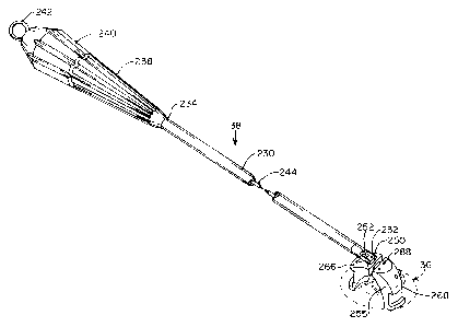
Introduces 38 will now be described with reference
to Figures 18-20. Introduces 38 includes a shaft 230
having a distal end 232, a proximal end 234, and an inner
lumen 236 therebetween. Shaft 230-has a length selected
to allow placement of replacement valve 36 in the mitral
valve position within the patient's heart from outside of
the patient's thoracic cavity, and is usually at least
about 20 cm in length, and preferably
about 25 cm to 35 cm in length. A handle 238 is attached
to proximal end 234, and a rotatable knob 240 is mounted
to handle 238 for pivoting the replacement valve 36
relative to shaft 230. A pull ring 242 extends
proximally from pivot knob 240 for releasing replacement
valve 36 from introduces 38. As best seen in Figures
20A-20B, push rod 244 extends through inner lumen 236,
and is coupled at its distal end 248 to a pivot 250 which
is pivotally mounted within a slot 252 at distal end 232
of shaft 230. -A-shank 254 extends distally from pivot
250 and has threads or other means for attachment to a
valve holder 255 for replacement valve 36. Knob 240 is
SUBSTITUTE SHEET (RULE 26)
W095115715 ~ PCT/US94/13305
fixed to a threaded shaft 256 received within a threaded
bore 258 in handle 238, whereby rotation of knob 240
translates threaded shaft 256 distally or proximally,
depending upon the direction of rotation. Push rod 244
5 has a proximal end 260 which engages a distal end 262 of
threaded shaft 256. A-spring 264 biases push rod 244 in
a proximal direction against distal end 262. In this
way, rotation of knob 240 pulls or pushes push rod 244,
thereby pivoting pivot 250 such that shank 254 extends
10 either distally or laterally.
Referring to Figures 19A-19G, valve holder 255
includes a stationary arm 266 attached to shank 254, and
a movable arm 268 pivotally mounted to stationary arm
266. Each of arms 266, 268 has an annular channel 270
15 configured to engage frame 218 of replacement valve 36
within flow channel 222 (Figure 17A). Arms 266, 268 are
further dimensioned and configured for introduction
through passage 50 of access cannula 22 when replacement
valve 36 is held in channels 270. As illustrated in
20 Figure 19A, when attached to shank 254 on introducer 38,
valve holder 255 may be pivoted in the direction of arrow
272 by rotation of knob 240. In this way, the
replacement valve 36 held by holder- 255 may be introduced
edge-first through passage 50 in access cannula 22, then
25 pivoted approximately 90° to an orientation suitable for
attachment in the mitral valve position within heart H.
To facilitate releasing replacement valve 36 from
holder 55 from a location outside of the patient's body,
a pull wire 274 is coupled to movable arm 268 by, for
30 example, an anchor ball 276 disposed within an aperture
278 (see Figure 20A). Pull wire 274 extends through an
inner lumen (not shown) in push rod 244, and is attached
at its proximal end 280 to pull ring 242. A spring 282
within an aperture 284 in knob 240 biases pull ring 242
35 in a distal direction. In this way, pulling on'pull ring
242 pivots movable arm 268 as shown in Figure 19C,
allowing replacement valve 36 to be removed from channels
SUBSTITUTE SHEET (RULE 26~
WO 95115715 PCTIUS94113305
2 ~'~'~ ~ 9 0
36
270. Anchor ball 276 and/or pull ring 242 may be
configured so as to be removable from pull wire 244,
allowing valve holder 255 to be removed from introduces
38 by decoupling arm 266 from shank 254. '
In order to keep replacement valve 36 on holder 255
when holder 255 is not attached to introduces 38, a pair
of holes 286 are provided in arm 266 in alignment with a
corresponding pair of holes 288 in arm 268. When
replacement valve 36 has been placed on holder 255, a
suture (not shown) may be tied through holes 286, 288 to
prevent pivoting of arm 268, thereby retaining
replacement valve 36 on holder 255. Once holder 255 has
been attached to introduces 38, the suture may be
removed, allowing arm 268 to pivot in response to
rotation of knob 240.
It will frequently be desirable for valve holder 255
and replacement valve 36 to-be pre-assembled, sterilized,
and packaged together in a single sterile pack. In this
way, upon opening the sterile pack in the operating room,
the replacement valve 36 and holder 255 are ready for
immediate surgical use. Further, it may be desirable for
introduces 38 to be sterilized with replacement valve 36
and included in the same sterile pack. In such cases,
holder 255 may be integrated with and non-removable from
introduces 38, with replacement valve 36 being mounted to
arms 266, 268 at the distal end of introduces 38 within
the sterile pack. Alternatively, introduces 38 may be a
reusable device which is attached to holder 255 and
replacement valve 36.in the operating room at the time of
the procedure.
As mentioned above, in order to select a replacement
valve 36 which is of the appropriate size for patient P,
valve annulus vA is usually sized prior to applying
sutures 198 to valve annulus vA. Sizing may be
accomplished in various ways, but in an exemplary
embodiment, is performed by means of a sizing disk 290,
illustrated in Figures 21-23, pivotally attached to
SUBSTITUTE SHEET (RULE 26)
W095115715 ~ PCT/US94/13305
37
introduces 38. Sizing disk 290 may be pivoted
approximately 90° relative to shaft 230 of introduces 38,
from an edge-first orientation suitable-for introduction
through access cannula 22, to a face-first orientation
suitable for sizing valve annulus vA. As shown in
Figures 22 and 23, sizing disk 290 is configured for
attachment to shank 254 of introduoer 38, preferably by
means of a threaded hole 292. A notch 294 is provided in
a proximal portion of disk 290 through which distal end
232 of shaft 230 may extend when disk 290 is in the
edge-first orientation. An aperture 296 is disposed in
the middle of disk 290 through which distal end 232 of
shaft 230 may extend when disk 290 is in the face-first
orientation. Preferably, a plurality of interchangeable
sizing disks 290 of various diameters are provided for
the procedure, allowing various sizing disks 290 to be
introduced into heart H and compared with valve annulus
DA until the diameter of the sizing disk corresponds to
that of valve annulus DA.
2o In place of sizing disk 290, an expandable balloon
or basket may be used for sizing valve annulus DA.
Fluoroscopy, transesophageal echocardiography (TEE),
epicardial or trans-thoracic ultra-sonography, or
angiography may also be used to facilitate sizing valve
annulus OA.
When the size of valve annulus DA has been
identified, sizing disk 290 may be removed from
introduces 38 and replaced by a replacement valve 36 of
the appropriate size, mounted on holder 255. Introduces
38 may then be clamped to support stand 34 with
replacement valve 36 positioned between first organizing
ring 30 and second organizing ring 32, as illustrated in
Figure 7.
Sutures 198 are applied to replacement valve 36 by
passing needles 200 through sewing ring 228 using needle
drivers 202. -Sutures 198 are then positioned in
circumferentially spaced positions on second organizing
SUBSTfTUTE SHEET (RULE 26~
WO 95115715 PCT/US94113305
38
ring 32. Second organizing ring 32 comprises, as
illustrated in Figures 24A-24C, an inner ring 298 fixed
to support stand 34, and an outer ring 300 rotatably
mounted to inner ring 298. An elastomeric retaining ring '
302 is disposed in an annular channel 304 in inner ring
298. Radial pins 303 are fixed-t'oyinner ring 298 and
extend through slots 305 in outer ring 300, thereby
limiting the rotation of outer-ring 300 relative to inner
ring 298. A plurality of slots 306 are disposed in
circumferentially spaced positions about inner ring 298,
and a corresponding number of slots 308 alignable with
slots 306 are disposed in outer ring 300. Retaining ring
302 has a plurality of slits 310 which are aligned with
slots 306 in inner ring 298. A clamp 312 for clamping
shaft 230 of introduces 38 is disposed on an extension
314 fixed to support stand 34.
After being applied to replacement valve 36, sutures
198 may be positioned within inner slots 306, slits 310,
and outer slots 308. Once all of sutures 298 have been
applied to replacement valve 36 and positioned in
organizing ring 32, outer ring 300-map be rotated
relative to inner ring 298, thereby locking sutures 298
in position.
Referring now to Figure 8A, replacement valve 36 may
then be introduced into the left atrium LA by advancing
introduces 38 through passage 50 of access cannula 22.
Replacement valve 36 is oriented on introduces 38 so as
to be introduced edge-first-through passage 50. As
replacement valve 36 is advanced into the thoracic
cavity, organizing ring 32 maintains tension on sutures
198, allowing replacEment valve 36 to slide along sutures
198. Introduces 38 is advanced through atriotomy 162 so
that replacement valve 36 is disposed within left atrium
LA. Replacement valve 36 is then pivoted on introduces
38 by rotating knob 240, so that sewing ring 228 of
replacement valve 36..(Figure 17A) may be aligned with
valve annulus 0A.
SUESTiTUTE SHEET (RUSE 2~~
WO 95!15715
PCT/US94/13305
39
Introducer 38 is then advanced further into left
atrium LA so as to position replacement valve 36 against
or within valve annulus 0A, as illustrated in Figure 8B.
Square or overhand knots are then formed in sutures 198
outside of the patient s thoracic cavity, and the knots
are pushed by a knot pusher 316 through passage 50 and
atriotomy 162 toward sewing ring 228 of replacement valve
36.
While knot pusher 316 may have a variety of
configurations, an exemplary embodiment is illustrated in
Figures 25A-25B. Knot pusher 316 comprises a shaft 318
having a distal end 320 and a proximal end 322, to which
is connected an actuator 324 constructed like actuator
120 described above in connection with Figure 12A.
Actuator 324 translates a push rod 326 extending through
shaft 318. A pair of movable jaws 328 are pivotally
mounted to distal end 320 of shaft 318, and are coupled
to push rod 326 such that proximal movement of push rod
326 opens jaws 328. A notch 330 at the distal end of
each jaw 328 is configured to receive a suture 198.
In use, a first free end of a suture 198 is tied in
a loop or slip knot over a second free end of suture 198,
and jaws 328 are positioned just proximal to the knot.
Jaws 328 are then opened such that each free end of
suture 198 is positioned within a notch 330 at the distal
end of jaws 328 and the slip knot is disposed centrally
between jaws 328. While holding tension on the free ends
of the sutures outside the thoracic cavity, knot pusher
316 is advanced distally, pushing the slip knot through
passage 50 of access cannula 22 and atriotomy 162 until
the slip knot engages sewing ring 228 of replacement
valve 36.
Referring now to Figure 9, when a plurality of knots
332 (usually 5 to 8) have been tied and pushed against
sewing ring 228 by knot pusher 316, knots 332 are
cinched down tightly, and free ends 334 are trimmed using
scissors 110 or other cutting device.
SUSSTiTUTE SHEEP (RULE 26)
CA 02177490 2005-07-22
It will be understood to those of ordinary skill in
the art that the thoracoscopic devices and methods
disclosed above for tissue manipulation, retraction,
cutting, suturing, and the like may be used to accomplish
5 procedures such as annuloplasty, commissurotomy,
quadrangular resection, shortening and reattachment of
chordae tendonae, and various other valve repair
procedures. To perform annuloplasty, valve annulus 0A is
contracted by suturing a portion of the valve annulus so
10 as to overlap an adjacent portion, or by attaching a
prosthetic annuloplasty device such as a Carpentier or
Duran annuloplasty ring (not shown) to valve annulus 0A
to reduce its diameter. To perform commissurotomy, the
valve leaflets vL are separated by cutting between them
15 where they have fused together due to calcification or
disease. To perform quandrangular resection, valve
leaflets vL are shortened or narrowed by excising a
portion of one or more leaflets VL, and reattaching the
remaining portions of the leaflet by suturing. The
20 chordae tendonae (not shown), which act as resilient
springs between valve leaflets VL and the papillary
muscles (not shown) attached to the heart wall in the
left ventricle LV, may be shortened by excising a portion
thereof and reattaching the ends of the remaining
25 portions by suturing. Similarly, severed chordae
tendonae may be restored by reattachment of the severed '
ends with sutures. Open-chest techniques for performing
such procedures are described in detail in Kirklin and
Barratt-Boyes, Cardiac Surgery, pp. 329-340.
When the valve replacement or other surgical
procedure in left atrium LA is completed, atriotomy 162
is closed. Sutures, thoracoscopic staples or other types
of closure devices may be used for this purpose. In one
embodiment, illustrated in Figure 10, atriotomy 162 is
closed by suturing, wherein needle drivers 202 are
CA 02177490 2005-07-22
41
introduced through trocar sleeves 24 and/or access
cannula 22, and a suture 336 having a needle 338 attached
to an end thereof is used to sew up atriotomy 162 using
conventional suturing techniques. Before and/or during
closure, a suction/irrigation tube (not shown) is usually
introduced through a trocar sleeve 24 and into left
atrium hA or left ventricle LV to remove any air therein
and to fill the heart chambers with a saline solution.
After atriotomy 162 has been closed, any remaining
instruments are removed from the thoracic cavity. A
chest tube may be introduced through one of trocar
sleeves 24 to facilitate evacuation of the pleural
cavity. Access cannula 22 and trocar sleeves 24 are then
removed from the chest wall, and the incisions or
penetrations through which they were introduced are
closed, usually by suturing or stapling.
The patient's lung may then be reinflated, and
cardiac function may be restarted.
infusion of
cardioplegic fluid through aortic occlusion catheter 82
and/or retroperfusion catheter 102 is discontinued, and a
saline solution is infused through one or both of these
catheters to irrigate the heart and coronary arteries
(see Figure 3). The saline solution, along with blood,
other fluids, air, thrombus, and other emboli within the
heart or coronary arteries are then aspirated through the
inner lumen of aortic occlusion catheter 82, as well as
through venous cannula 70 and/or pulmonary venting
catheter 79. occlusion balloon 88 on aortic occlusion
catheter 82 is then deflated, allowing warm, oxygenated
blood to flow into the coronary arteries to perfuse the
myocardium. Cardiac contractions will usually begin soon
thereafter. In some cases, electrical defibrillation may
be necessary to help restore cardiac function. Aortic
occlusion catheter 82 and retroperfusion catheter 102 may
then be removed from the patient. Cardiopulmonary bypass
WO 95115715 PCTIUS94113305
42
is then discontinued, and arterial-cannula 78, venous
cannula 70, and pulmonary venting catheter 79 are removed
from the patient.
In addition to performing mitral valve repair and
replacement, the techniques of-the invention also
facilitate surgical intervention.,into other regions of-
the heart and great vessels. The devices and methods
described above may be used to form an opening directly
into the left ventricle, right atrium, or right
ventricle, or into a great vessel such as the aorta,
superior vena cava, inferior vena cava, pulmonary artery,
or pulmonary vein, for surgical intervention in such
cavities. For example, a penetration may be made in the
wall of the aorta, and the aortic valve may be repaired
or replaced with a prosthesis, using techniques and
devices like those described above for mitral valve
replacement. Moreover, the devices and methods of the
invention also facilitate intracardiac procedures such as
repair of atrial or ventricular septal defects,
electrophysiological mapping and ablation of the
myocardium, myocardial drilling, and other procedures.
Furthermore, devices may be introduced through an opening
into the heart or great vessel and advanced therefrom
into vessels such as the coronary arteries to perform
procedures such as angioplasty, atherectomy, coronary
artery bypass grafting, or treatment of aneurysms.
While the above is a complete description of the
preferred embodiments of the invention, various
alternatives, modifications and equivalents may be used.
Therefore, the above description should not be taken as
limiting the scope of the invention, which is defined by
the appended claims.
SUBSTITUTE SHEET (RULE 26}