Sélection de la langue

Search

Sommaire du brevet 2177629 

Énoncé de désistement de responsabilité concernant l'information provenant de tiers

Une partie des informations de ce site Web a été fournie par des sources externes. Le gouvernement du Canada n'assume aucune responsabilité concernant la précision, l'actualité ou la fiabilité des informations fournies par les sources externes. Les utilisateurs qui désirent employer cette information devraient consulter directement la source des informations. Le contenu fourni par les sources externes n'est pas assujetti aux exigences sur les langues officielles, la protection des renseignements personnels et l'accessibilité.

Disponibilité de l'Abrégé et des Revendications

L'apparition de différences dans le texte et l'image des Revendications et de l'Abrégé dépend du moment auquel le document est publié. Les textes des Revendications et de l'Abrégé sont affichés :

  • lorsque la demande peut être examinée par le public;
  • lorsque le brevet est émis (délivrance).
(12) Brevet: (11) CA 2177629
(54) Titre français: OBTURATEUR A MACHOIRES POUR TETE DE PUITS
(54) Titre anglais: WELLHEAD PRODUCTION BLOWOUT PREVENTER RAM
Statut: Durée expirée - au-delà du délai suivant l'octroi
Données bibliographiques
Abrégés

Abrégé français

La couche de caoutchouc sur la mâchoire d'obturateur est renforcée aux points de scellement en formant des nervures sur l'âme de la mâchoire d'obturateur. Les nervures permettent à la bande de caoutchouc de résister à l'extrusion lorsque le bloc obturateur de puits est soumis à des pressions élevées dans le puits.


Abrégé anglais


The rubber layer on the ram is reinforced at the sealing areas by forming
ribs on the ram core. The ribs function to resist extrusion of the rubber layer when the
blowout preventer is subjected to high pressure from the well.

Revendications

Note : Les revendications sont présentées dans la langue officielle dans laquelle elles ont été soumises.


THE EMBODIMENTS OF THE INVENTION IN WHICH AN EXCLUSIVE
PROPERTY OR PRIVILEGE IS CLAIMED ARE DEFINED AS FOLLOWS:
1. In a production blowout preventer comprising a housing forming a
vertical bore extending longitudinally therethrough and a pair of coaxial horizontal ram
bores extending transversely thereof and intersecting the vertical bore to form opposed
sealing areas, said ram bores each containing a generally cylindrical ram, the rams
being slidable along the ram bores so as to project into the vertical bore where they
may seal against a rod string extending therethrough or may contact to close the
vertical bore if the rod string is absent, each ram comprising a rigid core having a
cylindrical outer end portion whose diameter is close to that of the horizontal bore
containing it, a cylindrical inner end portion having a comparatively reduced diameter,
and a vertical inner end face, said core inner end portion and inner end face being
covered by a layer of elastomer bonded thereto, the improvement comprising:
each ram core inner portion having ribs projecting outwardly therefrom
and extending longitudinally therealong so as to underlie the elastomer layer at the
sealing areas, said elastomer layer being thinned over the ribs to maintain the diameter
of the inner portion, said ribs being operative to reinforce the elastomer layer opposite
the sealing areas against upward extrusion by pressure in the segment of the vertical
bore located beneath the ram bores.
2. The improvement as set forth in claim 1 wherein:
the core inner end face forms a plurality of spaced apart indentations, so
that the elastomer extends into the indentations.

Description

Note : Les descriptions sont présentées dans la langue officielle dans laquelle elles ont été soumises.

~ 2 1 7762q
TECHNICAL FIELD
2 This invention relates to the rams used in a wellhead production blowout
3 preventer.
4 BACKGROU~ID ART
The invention has to do with improving the rams in a known oilfield
6 wellhead assembly cu,,,,uor,~ known as a production blowout preventer (hereafter
7 "BOP").
8 This type of BOP is commonly used in connection with pumping wells.
9 With such wells, a sucker rod string is It~ U~,dlt:d or rotated to drive a downhole
pump, which lifts the produced fluid to surface through a tubing string.
11 The BOP is equipped with rams which can be advanced ho,i~u"~"y to
12 seal around the vertical polish rod of the rod string, to prevent the upward escape of
13 fluid. Altematively, if the rod string is out of the well, the inner ends of the rams can
14 be pressed together to effect closure of the wellhead assembly fluid passag~/.
More particularly, the BOP comprises a cross-shaped housing forming
16 a vertical bore and a pair of coaxial, horizontal ram bores il "c:,~e.,li"g the vertical bore
17 from each side. The BOP is commonly positioned in the wellhead assembly between
18 the tubing head and flow tee. The BOP vertical bore therefore forms part of the
19 wellhead assembly fluid passag~~,/.
A pair of rams is positioned in the ram bores. Means, such as screw
21 jacks, are provided at the outer ends of the bores, for advancing or retracting the rams
22 into or out of the vertical bore.

21 77629
Each ram comprises a generally cylindrical body. The body comprises
2 a steel core having an outer full diameter portion and a reduced diameter inner portion.
3 ThQ core inner portion is covered with and bonded to a layer of elastomer, typically
4 nitrile rubber.
The cylindrical ram bores extend into the vertical bore and the bore
6 surfaces combine at their i~ 6~.1iOIl to form sealing areas. When the rams move into
7 the vertical bore, the rubber surfaces of their inner portions seal against the sealing
8 surfaces.
9 The rubber-coated inner face of each ram is formed to provide a semi-
circular, vertically directed groove. Thus, when the polish rod of the rod string is
11 present in the vertical bore, the ram ends encircle and press against it, to effect a seal.
12 When the polish rod is not in the vertical bore, the ram ends compress together to form
13 a solid block. In both cases, the circumferential seals of the ram side surfaces with the
14 sealing areas and the end face seals combine to close the vertical bore and contain
pressurized fluids seeking to pass therethrough.
16 One problem ~Cso~iAtpd with production BOP's is that the pressure
17 acting from below on the closed rams may extrude the side rubber upwardly so that
18 the circumferential seal with the sealing areas is lost.
19 Another problem is that the end rubber bonded to the vertical end faces
of the ram cores may tear loose from the core when high pressure is exerted from2~ below.

2 1 7762~
It is therefore an objective of the invention to provide an improved ram,
2 which when used in col, ,L,i,~Liùn with the BOP housing, is better able to withstand high
3 pressure from below without losing the side seal. It is a preferred objective to provide
4 such a ram wherein the rubber is more securely bonded to the core end face, so that
5 it may better resist being torn loose.
6 SUMMARY OF THE INVENTION
7 In a~cu,~ ce with the main feature of the invention, the side surface of
8 each ram core inner portion is formed to provide ribs extending outwardly therefrom
9 and extending longitudinally thereof. The ribs are located so as to underlie those
portions of the elastomer layer which seal against the sealing areas. The elastomer
11 layer is thinned where it passes over the ribs, to preserve the cylindrical shape of the
12 ram's inner portion.
13 The ribs function to reinforce the elastomer layer against upward
14 extrusion. Comparative pressure tests have shown that a ribbed ram was able to
contain several times the pressure that a non-ribbed ram could contain, before the seal
16 was lost.
17 The eA~,~ssiul1 "ribs" is to be widely construed. The ribs may be
18 continuous or discontinuous. What is needed is a rigid, elongate, horizontal
19 ,~i,,fun,~ of the elastomer layer along each side of the ram, opposite the sealing
areas.

2 1 77629
In acconial1ce with a preferred feature, the vertical end face of the core
2 inner portion is indented, for example with a plurality of spaced apart transverse
3 grooves or dimples or a single cavity, so that the base of the elastomer layer projects
4 into these i,~de"l~lions. As a result, increased face surface area is provided to bond
5 with the elastomer. In addition, the elastomer external of the il~d~ s must shear
6 from the elastomer in the il1d~ liolls~ before failure occurs and the elastomer
7 separates from the steel. In this way, the resistance to failure of the elablu",er/bl~el
8 bond at the ram end faces is improved.
9 DESCRIPTION OF THE DRAWING
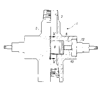
1û Figure 1 is a partly sectional side view of a production blowout preventer
11 in acco,~tl".,e with the invention;
12 Figure 2 is a partly sectional p~ e.;li.r~ view showing the production
13 blowout preventer of Figure 1;
14 Figure 3 is a p~,~,u~c.i;c view of the steel core forming part of the ram;
Figure 4 is a pc,~u~.. Li;c view of the ram Culll~ l9 the core having its
16 inner portion covered with molded rubber;
17 Figure 5 is a sectional end view showing a ram extended into the vertical
1 8 bore;
19 Figure 6 is a perspective view of the core having grooves formed in its
inner end face;
21 Figure 7 is a pe,~pe.,;i/c view of the core having dimples formed in its
22 inner end face; and
23 , Figure 8 is a p~,:" e~,.;/c view of the core having a pocket formed in its
24 end face.

~ 21 7762~
DESCRIPTION OF THE PllLI Lllr~LU EMBODIMENT
2 Having reference to Figures 1 and 2, the production blowout preventer
3 1 comprises a cross-shaped housing 2 forming a vertical bore 3 and a pair of coaxial
4 horizontal ram bores 4,5. The ram bores 4,5 intersect with the vertical bore 3 and form
sealing areas 6a, 6b.
6 A pair of generally cylindrical rams 7,8 are located within the ram bore
7 4,5. Screw jacks 9,10 extend through plugs 11,12 threaded into the outer ends of the
8 ram bores 4,5. The screw jacks 9,10 can be turned to advance or retract the rams 7,8
9 into or out of the vertical bore 3.
A steel core 20 is shown in Figure 3. The core 20 comprises inner and
11 outer portions 21, 22.
12 The outer portion 22 has a full diameter, so as to maintain a close sliding
13 fit with the surface of the ram bore containing it. The outer portion 22 carries O-ring
14 seals 23 seated in circumferential grooves formed by its outer surface 24.
The core inner portion 21 has a comparatively reduced diameter. Its
16 inner end face 25 forms a vertical grove 26.
17 A pair of reinforcing ribs 27, 28 protrude outwardly from and extend
18 longitudinally of the core inner portion 21. The ribs 27,28 are positioned opposite the
19 sealing areas 6a, 6b.
Preferably, inde"Ldliol1s 30 are fonmed in the core's inner end face 25,
21 as shown in Figures 6-8.

2 ~ 77629
A layer 31 of rubber is molded onto the core inner portion 21, as shown
2 in Figures 4, 5. The layer 31 is thinned over the ribs 27, 28 and extends into the
3 illd_ll 'ic.ls 30. A vertical groove 32 is formed to receive the polish rod (not shown).
4 Testing was conducted using an asse,l,l,led BOP and polish rod. The
rams were engaged with the rod and ~I) dl~ - pressure was applied below the rams.
6 Several rams, both with and without ribs, were tested to determine their pressure
7 holding capability. The rams without ribs failed at about 500 - 600 psi. The same
8 rams, but having ribs, failed at about 3700 psi.

Dessin représentatif
Une figure unique qui représente un dessin illustrant l'invention.
États administratifs

2024-08-01 : Dans le cadre de la transition vers les Brevets de nouvelle génération (BNG), la base de données sur les brevets canadiens (BDBC) contient désormais un Historique d'événement plus détaillé, qui reproduit le Journal des événements de notre nouvelle solution interne.

Veuillez noter que les événements débutant par « Inactive : » se réfèrent à des événements qui ne sont plus utilisés dans notre nouvelle solution interne.

Pour une meilleure compréhension de l'état de la demande ou brevet qui figure sur cette page, la rubrique Mise en garde , et les descriptions de Brevet , Historique d'événement , Taxes périodiques et Historique des paiements devraient être consultées.

Historique d'événement

Description Date
Exigences relatives à la révocation de la nomination d'un agent - jugée conforme 2020-09-01
Inactive : Périmé (brevet - nouvelle loi) 2016-05-29
Requête visant le maintien en état reçue 2013-05-22
Inactive : Lettre officielle 2007-03-14
Inactive : Paiement correctif - art.78.6 Loi 2007-01-17
Requête d'examen reçue 2000-04-06
Inactive : Correspondance - Formalités 2000-04-06
Accordé par délivrance 1999-09-21
Inactive : Page couverture publiée 1999-09-20
Préoctroi 1999-06-10
Inactive : Taxe finale reçue 1999-06-10
Un avis d'acceptation est envoyé 1999-03-19
Lettre envoyée 1999-03-19
Un avis d'acceptation est envoyé 1999-03-19
Inactive : Renseign. sur l'état - Complets dès date d'ent. journ. 1999-03-15
Inactive : Dem. traitée sur TS dès date d'ent. journal 1999-03-15
Inactive : Approuvée aux fins d'acceptation (AFA) 1999-02-15
Demande publiée (accessible au public) 1997-11-30
Exigences pour une requête d'examen - jugée conforme 1996-05-29
Toutes les exigences pour l'examen - jugée conforme 1996-05-29

Historique d'abandonnement

Il n'y a pas d'historique d'abandonnement

Taxes périodiques

Le dernier paiement a été reçu le 1999-05-25

Avis : Si le paiement en totalité n'a pas été reçu au plus tard à la date indiquée, une taxe supplémentaire peut être imposée, soit une des taxes suivantes :

  • taxe de rétablissement ;
  • taxe pour paiement en souffrance ; ou
  • taxe additionnelle pour le renversement d'une péremption réputée.

Veuillez vous référer à la page web des taxes sur les brevets de l'OPIC pour voir tous les montants actuels des taxes.

Titulaires au dossier

Les titulaires actuels et antérieures au dossier sont affichés en ordre alphabétique.

Titulaires actuels au dossier
STREAM-FLO INDUSTRIES LTD.
Titulaires antérieures au dossier
KEITH D. FARQUHARSON
TONY M. LAM
Les propriétaires antérieurs qui ne figurent pas dans la liste des « Propriétaires au dossier » apparaîtront dans d'autres documents au dossier.
Documents

Pour visionner les fichiers sélectionnés, entrer le code reCAPTCHA :


Pour visualiser une image, cliquer sur un lien dans la colonne description du document. Pour télécharger l'image (les images), cliquer l'une ou plusieurs cases à cocher dans la première colonne et ensuite cliquer sur le bouton "Télécharger sélection en format PDF (archive Zip)" ou le bouton "Télécharger sélection (en un fichier PDF fusionné)".

Liste des documents de brevet publiés et non publiés sur la BDBC .

Si vous avez des difficultés à accéder au contenu, veuillez communiquer avec le Centre de services à la clientèle au 1-866-997-1936, ou envoyer un courriel au Centre de service à la clientèle de l'OPIC.


Description du
Document 
Date
(aaaa-mm-jj) 
Nombre de pages   Taille de l'image (Ko) 
Page couverture 1998-02-02 1 29
Dessins 1999-02-03 5 161
Dessin représentatif 1998-02-02 1 7
Page couverture 1996-09-09 1 14
Description 1996-09-09 6 175
Dessins 1996-09-09 5 135
Revendications 1996-09-09 1 39
Abrégé 1996-09-09 1 8
Dessin représentatif 1999-09-13 1 7
Page couverture 1999-09-13 1 30
Rappel de taxe de maintien due 1998-02-02 1 111
Avis du commissaire - Demande jugée acceptable 1999-03-19 1 164
Taxes 2003-05-27 1 29
Correspondance 1999-06-10 1 38
Taxes 2000-03-21 1 35
Taxes 2000-04-06 1 48
Correspondance 2000-04-06 1 50
Taxes 1998-05-26 1 35
Taxes 2002-04-08 1 35
Taxes 2001-05-04 1 31
Taxes 1999-05-25 1 32
Taxes 2004-05-19 1 30
Taxes 2005-04-15 1 28
Taxes 2006-04-25 1 28
Correspondance 2006-05-15 4 140
Correspondance 1999-03-19 1 86
Correspondance 2007-03-14 1 15
Taxes 2007-04-25 1 29
Taxes 2008-05-23 1 28
Taxes 2009-05-26 1 26
Taxes 2010-04-19 1 29
Taxes 2011-04-05 1 33
Taxes 2012-04-30 1 32
Taxes 2013-05-22 1 33
Taxes 2014-05-21 1 24