Note : Les descriptions sont présentées dans la langue officielle dans laquelle elles ont été soumises.
~~71643
1
BACKGROUND OF THE INVENTION
Field of the Invention
The invention is directed to a method for the production of pipes, in
particular
large pipes, by the UOE process.
Description of the Prior Art
The process known in technical circles as the UOE process is the most
frequently applied
method for the production of longitudinal seam-welded large pipes (Stradtmann,
Stahlrohr-
Handbuch, 10th edition, Vulkan-Verlag, Essen 1996, pages 164-167). In this
process, a U-
shaped slit pipe is shaped in a first step from a planar sheet of metal on a
press with open dies
(U-press). The rounding process for forming a pipe is then effected in a
second step by self
closing dies (O-press). Since the pipes in many cases do not yet meet
requirements for diameter
and roundness after inner and outer welding, they are sized by means of cold
expansion
(Expansion). At the same time, as a result of this expansion, some of the
internal tensile stress
which builds up during production and welding is partially removed and is even
transformed into
internal compressive strain along most of the circumference (company brochure
by Mannesmann
Grol3rohr, published by MRW, Diisseldorf, 1980, pages 114-1239).
As a result of the cold expansion, pipes which are produced by the UOE process
exhibit
changes in strength characteristics and deformation characteristics compared
to the starting sheet
~ 7163
2
metal. These changes are characterized by a lack of homogeneity at the pipe
circumference and
by pronounced deformation anisotropy.
These changes lead to an impairment of the use characteristics and of the
dependability
of structural members in particular for thick-walled offshore pipes and pipes
made from grades
of steel with a high elastic limit/tensile strength ratio.
X117643
3
SUMMARY OF THE INVENTION
Accordingly, it is an object of the present invention to provide a process for
producing
pipes, in particular large pipes, by the UOE process, in which the strength
characteristics and
deformation characteristics in the circumferential direction of the pipe are
rendered substantially
homogeneous and in which determined characteristics can be adjusted in a
directed manner.
Pursuant to this object, and others which will become apparent hereafter, one
aspect of
the present invention resides in conditioning the pipes by a combined
application of cold
expansion and cold reduction, wherein the sequence and degree of expansion and
reduction,
respectively, can be established depending on the required profile.
The advantages of the process according to the invention are as follows:
1. the strength characteristics and deformation characteristics in the
circumferential direction
of the pipe are made homogeneous, also from one pipe to the next, which
results in
reduced variation of individual characteristic features;
2. the pipe flow characteristics are improved in accordance with their
intended use for
internal and/or external pressure loading;
3. the flowability of the pipe can be adjusted in a directed manner depending
on the
intended use for internal or external pressure loading;
2T17643
4
4. the collapsing pressure and the dependability of structural members of
offshore pipes are
increased;
5. grades of steel with a particularly high elastic limit/tensile strength
ratio can be processed
in an improved manner;
6. the circumferential internal stresses at the pipe circumference are made
homogeneous;
7. the deformability of the pipe in the uniform elongation range is increased;
8. the dimensional stability and pipe geometry (prevention of noncircularity
and peaking)
is improved; and
9. the shaping forces occurring in the O-press and during cold expansion can
be reduced.
The last advantage is particularly important for thick-walled pipes, since the
O-press and
the conventionally used mechanical expander are worked to the load limit.
Since some of the
required shaping overlaps with the conditioning, the loading can accordingly
be reduced for the
O-press as well as for the mechanical expander.
The process mentioned above can also be used for the three-roll bending
process with
integrated cold expansion. In this case, in contrast to the UOE process, less
importance is
CA 02177643 2004-O1-09
20337-455
placed on homogenization than on the adjustment of the
strength characteristics and pipe geometry.
According to an aspect of an embodiment of the
invention there is provided a process for producing a pipe
5 pursuant to the UOE process, comprising the steps of:
shaping the pipe from a metal sheet; internally and
externally welding a seam of the pipe to form a closed
circumference; sizing the pipe by cold expansion after the
welding step; and conditioning the pipe by cold expansion
and cold reduction in a sequence and to a degree of
expansion and reduction based on a requirement profile. In
some embodiments the conditioning step includes reducing the
pipe up to 2o and subsequently expanding the pipe up to 40
to a reference dimension. In other embodiments the
conditioning step includes expanding the pipe up to 2o and
subsequently reducing the pipe up to 4o to a reference
dimension.
The various features of novelty which characterize
the invention are pointed out with particularity in the
claims annexed to and forming a part of the disclosure. For
a better understanding of the invention, its operating
advantages, and specific objects attained by its use,
reference should be had to the drawing and descriptive
matter in which there are illustrated and described
preferred embodiments of the invention.
~ ~ 11643
6
.BRIEF DESCRIPTION OF THE DRAWINGS
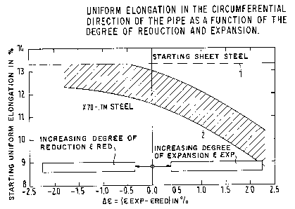
Figure 1 is a graph of the uniform elongation in the circumferential direction
of the pipe as a
function of the degree of reduction and expansion;
Figure 2 is a graph of the elastic limit/tensile strength ratio in the
circumferential direction of
the pipe as a function of the degree of reduction and expansion;
Figure 3 is a graph of the Rr0.5 yield point along the circumference of the
pipe as a function of
internal or external pressure, where graph a) shows the prior art process and
graph b) shows the
process according to the invention;
Figure 4 is a stress-strain diagram for production and testing according to
the prior art process;
Figure 5 is a stress-strain diagram for production and testing according to
the inventive process
for the production of onshore pipes; and
Figure 6 is a diagram as in Fig. 5, but for the production of offshore pipes.
271643
DETAILED DESCRIPTION OF THE PREFERRED EMBODIMENTS
Figure 1 shows a graph of the uniform elongation in the circumferential
direction of the
pipe as a function of the degree of reduction and expansion. The uniform
elongation is plotted
as a percentage on the ordinate, and the degree of deformation resulting from
reduction and
expansion is plotted as a percentage on the abscissa. The fine dotted straight
line 1 is the
uniform elongation for the starting sheet metal material, e.g., for X70-TM,
i.e.,
thermomechanically rolled steel. In this graph, the uniform elongation lies
above 13 % . The
curved band 2 located below the line 1 shows the variation in the test values.
At 0
deformation, the uniform elongation values already lie below those of the
sheet steel due to the
pipe production. If the pipe is considerably expanded in the course of pipe
production, the
uniform elongation decreases sharply as is clearly shown by the graph. On the
other hand, if
the pipe is reduced, the uniform elongation increases and can regain the
starting value of the
sheet steel as an individual value or even as a mean value depending on the
degree of reduction.
Figure 2 shows a graph of the elastic limit/tensile strength ratio in the
circumferential
direction of the pipe as a function of the degree of reduction and expansion.
The elastic
limit/tensile strength ratio R~0.5/R", is plotted on the ordinate and the
degree of deformation is
shown as a percentage on the abscissa. The fine dotted straight line 3 is the
elastic limit/tensile
strength ratio for the starting sheet metal material. This ratio should be
0.8, for example. The
bold solid line 4 shows the increase in the elastic limit/tensile strength
ratio as the degree of
expansion increases. The continuation of this line in the left half of the
graph shows the
decrease in the elastic limit/tensile strength ratio when expansion is
increasingly superimposed
~~11643
g
on the preceding reduction. On the other hand, if a reduction of the pipe is
immediately halted,
this gives the dash-dot line 5. This line 5 clearly shows that the elastic
limit/tensile strength
ratio drops sharply compared to the initial value of the sheet metal as the
result of even a small
reduction.
Figure 3 shows two partial graphs illustrating the R~0.5 yield point along the
pipe
circumference as a function of internal or external pressure. In the
conventional process (graph
a)), the yield point values under loading by external pressure lie
considerably below those under
loading by internal pressure. This means that the pipe has a low collapsing
resistance.
Furthermore, the curve along the pipe circumference shows that the values are
not uniformly
distributed. This means that influences of pipe production are still readily
apparent and
determine the behavior of structural members under internal or external
pressure. When
applying the new process according to the invention (graph b)), the values
become uniform along
the pipe circumference. The yield point under external pressure loading is
appreciably higher
so that the pipe produced in this way has a greater resistance to collapsing.
Stress-strain diagrams are shown in Figures 4 and S. The stress is plotted in
megapascals
on the ordinate and the percent deformation is plotted on the abscissa.
Figure 4 shows the stress curve during the production of line pipe according
to the
conventional process. The solid line, proceeding from the coordinate origin
zero along point
A to point B, shows the change in stress during production. A certain
reduction takes place in
the O-press and is characterized here by curve segment 6.1. After welding, an
intensive
expansion is effected by means of a mechanical expander which is represented
in the graph by
curve 6.2 which extends to point A. After relieving, the stress drops to the
value at point B.
CA 02177643 2004-O1-09
20337-455
9
When a specimen is taken for the tensile test in the case of
a pipe produced in this way, the stress/strain follows the
curve segment 7 which is shown in dashes, wherein the yield
point is reached at point F and another elongation limit is
reached at point C. Conversely, when a pressure test is
carried out instead of a tensile tests, the stress/strain
follows the curve 8, for example, wherein the yield point is
reached at F' and another strain limit is reached at C'.
However, due to the Bauschinger effect, the ordinate value
F'9 is significantly less than the value F corresponding to
the ordinate 10 in the tensile test. These ratios change
when applying the process according to the invention.
Figure 5 shows the ratios in the manufacture of
onshore pipes. In these pipes, a high reduction is first
applied according to the invention corresponding to the
solid curve 11, starting at the coordinate origin zero.
Expansion is then effected corresponding to curve 12 until
point A. As shown in Figure 5, typically the pipe may be
reduced by approximately 2o in the reduction step and may be
expanded up to approximately 40 of a reference dimension in
the expansion step. After relieving, the stress drops to
the value at point B. The tensile test gives the yield
point at an ordinate value F13 which is relatively equal to
that shown in Figure 4 according to the conventional
process. The decisive difference consists in the ordinate
value F'14 at the reversal of deformation. This value F' is
approximately equal to value F and perhaps even somewhat
greater.
Figure 6 shows the ratios in the production of
offshore pipes.
CA 02177643 2004-O1-09
20337-455
9a
In this case, the pipe is first homogenized by expansion
according to the invention and is then adjusted with respect
to diameter and strain limit by reduction. The rise in
stress is shown by the thick solid curve 15 starting at the
coordinate origin 0. The drop at the cessation of reduction
is shown in curve 16 to point A. As shown in Figure 6,
typically the pipe may be expanded by approximately 2o in
the expansion step and may be reduced by approximately 40 of
a reference dimension in the reduction step. After
relieving, the stress decreases to the value at point B.
When a tensile test is carried out again, the stress
increases to the ordinate value 18 at point F corresponding
to the
~~ ' L 1 l l 6 4 3
dashed line 17. This point lies somewhat below the comparable values F
corresponding to
Figures 4 and 5. The reverse, i.e., the pressure test, gives an ordinate value
19 at point F'
which is considerably greater than the value determined in the tensile test.
The invention is not limited by the embodiments described above which are
presented as
examples only but can be modified in various ways within the scope of
protection defined by the
appended patent claims.