Sélection de la langue

Search

Sommaire du brevet 2178334 

Énoncé de désistement de responsabilité concernant l'information provenant de tiers

Une partie des informations de ce site Web a été fournie par des sources externes. Le gouvernement du Canada n'assume aucune responsabilité concernant la précision, l'actualité ou la fiabilité des informations fournies par les sources externes. Les utilisateurs qui désirent employer cette information devraient consulter directement la source des informations. Le contenu fourni par les sources externes n'est pas assujetti aux exigences sur les langues officielles, la protection des renseignements personnels et l'accessibilité.

Disponibilité de l'Abrégé et des Revendications

L'apparition de différences dans le texte et l'image des Revendications et de l'Abrégé dépend du moment auquel le document est publié. Les textes des Revendications et de l'Abrégé sont affichés :

  • lorsque la demande peut être examinée par le public;
  • lorsque le brevet est émis (délivrance).
(12) Brevet: (11) CA 2178334
(54) Titre français: DISPOSITIF A MONTER SUR DES PYLONES DE LIGNES DE TRANSPORT DE FORCE
(54) Titre anglais: DEVICE AT POWER LINE POLES
Statut: Périmé et au-delà du délai pour l’annulation
Données bibliographiques
(51) Classification internationale des brevets (CIB):
  • A63B 27/00 (2006.01)
  • E06C 07/18 (2006.01)
  • E06C 09/04 (2006.01)
(72) Inventeurs :
  • MALMGREN, ULF (Suède)
(73) Titulaires :
  • ULF MALMGREN
(71) Demandeurs :
  • ULF MALMGREN (Suède)
(74) Agent: BATTISON WILLIAMS DUPUIS
(74) Co-agent:
(45) Délivré: 2004-02-10
(86) Date de dépôt PCT: 1994-11-23
(87) Mise à la disponibilité du public: 1995-06-15
Requête d'examen: 1999-04-28
Licence disponible: S.O.
Cédé au domaine public: S.O.
(25) Langue des documents déposés: Anglais

Traité de coopération en matière de brevets (PCT): Oui
(86) Numéro de la demande PCT: PCT/SE1994/001117
(87) Numéro de publication internationale PCT: SE1994001117
(85) Entrée nationale: 1996-06-05

(30) Données de priorité de la demande:
Numéro de la demande Pays / territoire Date
9304098-8 (Suède) 1993-12-07

Abrégés

Abrégé français

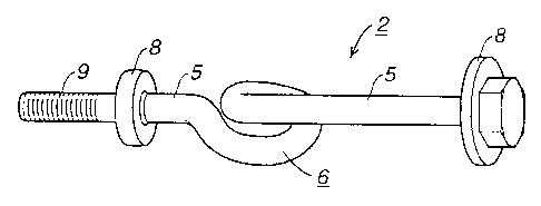
L'invention concerne un système permettant de grimper sur un pylône de ligne de transport de force (1), par exemple, sans risque de chute, des supports de pied (5) étant prévus le long dudit pylône. Lesdits supports de pied (5) comprennent un cale-pied de sécurité (6) permettant de grimper avec une corde de sauvetage (7) que l'on peut insérer ou enlever simplement d'une main. Le cale-pied (6) de sécurité est doté d'une partie courbée dont les extrémités sont reliées au support de pied (5) de sorte que les parties de ce dernier présentent des axes centraux coïncidants, de chaque côté de la partie courbée.


Abrégé anglais


The present invention re-
lates to an arrangement to en-
able climbing in a power-line
pylon (1), for instance, without
the risk of falling, foot-rests (5)
being provided along said py-
lon. These foot-rests (5) com-
prise a safety foothold (6) en-
abling climbing with a life-line
(7) that is inserted or removed
with a simple one-hand action.
The safety foothold (6) is pro-
vided with a bent part, the ends
of which are connected to the foot-rest (5) so that the parts of the foot-rest on each side of the bent part have coinciding central axes.

Revendications

Note : Les revendications sont présentées dans la langue officielle dans laquelle elles ont été soumises.


4
CLAIMS:
1. A climbing device with a safety foothold comprising:
a rod, said rod having a first and a second end, a bent section therebetween
adapted to
receive a life-line and straight sections on both sides of said bent section,
at least one
straight section being adapted to define a footrest wherein said bent section
is an open
loop which is hook shaped, a hooked end of which bends back upon itself such
that said
straight sections on both sides of said bent section have coinciding central
axes, said
straight sections and bent section being a continuous rod of uniform cross
section.
2. The device according to claim 1 further comprising a flange provided at
least one end of said rod.
3. The device according to claim 1 further comprising an attachment part
provided at one end of said device whereby said device may be attached to an
object to
be climbed.
4. The device according to claim 3 being attached at said attachment part to
a power-line pylon.

Description

Note : Les descriptions sont présentées dans la langue officielle dans laquelle elles ont été soumises.


CA 02178334 2003-07-30
DEVICE AT POWER LINE POLES
TECHNICAL FIELD:
The present invention relates to an arrangement to enable climbing in a power-
line pylon, for instance, without the risk of falling, foot-rests being
provided along said
pylon.
BACKGROUND ART, PROBLEMS
According to official regulations safety arrangements shall be used when
climbing in a power-line pylon, for instance when carrying out repairs or
maintenance.
Climbing is normally performed on foot-rests arranged along the power-line
pylons.
Climbing also occurs in the trusses in the power-line pylons. One method of
providing
protection against failing when climbing on foot-rests or trusses is to use a
life-line.
When climbing is started a first end of the life-line is secured in a steel
rope extending
between the upper and lower part of the pylon, running over a block at the top
of the
pylon. The steel wire is used to pull the life-line over the block. The other
end of the life-
line is secured to a belt worn by the climber, after which climbing can
commence and
the life-line affords protection against falling.
The problem with climbing using the life-lines described above is that the
steel
rope arranged in the pylon is an expensive arrangement that often disappears
due to
theft.
The object of the invention is to provide an arrangement that is simple to
use,
thereby enabling climbing without the risk of falling.
SUMMARY OF THE INVENTION, ADVANTAGES
The invention aims at solving these and other associated problems.
According to one aspect of the present invention there is provided a climbing
device with a safety foothold comprising: a rod, said rod having a first and a
second
end, a bent section therebetween adapted to receive a life-line and straight
sections on
both sides of said bent section, at least one straight section being adapted
to define a

CA 02178334 2003-07-30
2
footrest wherein said bent section is an open loop which is hook shaped, a
hooked end
of which bends back upon itself such that said straight sections on both sides
of said
bent section have coinciding central axes, said straight sections and bent
section being
a continuous rod of uniform cross section.
The invention is characterized in that said foot-rests comprise a safety
foothold
enabling climbing with a life-line that is inserted into or removed from the
safety foothold
with a simple one-hand action while climbing, the safety foothold having a
bent part the
ends of which are connected to the foot-rest so that the parts of the foot-
rest on each
side of the bent part have coinciding central axes.
Such an arrangement is simple to manipulate since the line will run parallel
to the
attachment. Protection against falling during climbing is ensured by designing
the safety
foothold as an open loop to receive the life-line.
The foot-rest is shaped in known manner and consists of a rod with a first and
a
second end, each end being provided with an anti-slip device in the form of a
flange.
The protection against falling, or safety foothold, is between the flanges.
The open loop
in the safety foothold can be produced in many different ways, one of which is
described
below by way of example.
It is not necessary for every foot-rest position along the pylon to be
provided with
a device according to the invention. It may be suitable for every second or
third foot-rest
position to be provided with a device according to the invention, while the
intermediate
positions are provided with conventional foot-rests.
A further advantage of the invention is that the arrangement of foot-rests
with
safety footholds in power-line pylons, for instance, enables the climber to
place the life-
line in the safety foothold using only one hand while climbing up or down or
laterally in
either direction, and still be protected against falling.
BRIEF DESCRIPTION OF THE DRAWINGS
The invention is described in more detail by way of example in the
accompanying

CA 02178334 2003-07-30
3
drawings, in which Figure 1 shows schematically an example of a power-line
pylon
provided with an arrangement according to the invention. Figure 2 shows an
embodiment of the device according to the invention.
PREFERRED EMBODIMENT
Figure 1 shows schematically an example of a power-line pylon 1 provided with
a
device 2 according to the invention, secured to several foot-rest positions
along one of
the frame posts 3 of the pylon 1. Diagonals 4 are arranged between the frame
posts.
The pylon 1 shown in the drawings is made of steel but the device can of
course be
used on pylons of concrete or other materials.
Foot-rests 5 including a safety foothold 6 are arranged in at least some of
the
foot-rest positions, see Figure 2, to permit climbing with a life-line 7 that
is inserted or
removed from the safety foothold 6 with a simple one-hand action during
climbing. The
safety foothold 6 comprises an open loop for receipt of the life-line.
Figure 2 shows an embodiment of the device 2 according to the invention. The
device comprises a foot-rest part 5 with anti-slip device 8 at each end, an
attachment
part 9 being arranged at one anti-slip device 8 of the foot-rest part 5. The
safety foothold
6 is arranged between the two anti-slip devices 8 of the foot-rest part 5. The
safety
foothold 6 consists of a bent part, the ends of which are connected to the
foot-rest part 5
so that the parts of the foot-rest 5 on each side of the bent part have
coinciding central
axes.

Dessin représentatif
Une figure unique qui représente un dessin illustrant l'invention.
États administratifs

2024-08-01 : Dans le cadre de la transition vers les Brevets de nouvelle génération (BNG), la base de données sur les brevets canadiens (BDBC) contient désormais un Historique d'événement plus détaillé, qui reproduit le Journal des événements de notre nouvelle solution interne.

Veuillez noter que les événements débutant par « Inactive : » se réfèrent à des événements qui ne sont plus utilisés dans notre nouvelle solution interne.

Pour une meilleure compréhension de l'état de la demande ou brevet qui figure sur cette page, la rubrique Mise en garde , et les descriptions de Brevet , Historique d'événement , Taxes périodiques et Historique des paiements devraient être consultées.

Historique d'événement

Description Date
Le délai pour l'annulation est expiré 2008-11-24
Lettre envoyée 2007-11-23
Inactive : CIB de MCD 2006-03-12
Accordé par délivrance 2004-02-10
Inactive : Page couverture publiée 2004-02-09
Inactive : Taxe finale reçue 2003-11-28
Préoctroi 2003-11-28
Un avis d'acceptation est envoyé 2003-10-10
Lettre envoyée 2003-10-10
Un avis d'acceptation est envoyé 2003-10-10
Inactive : Approuvée aux fins d'acceptation (AFA) 2003-09-22
Modification reçue - modification volontaire 2003-07-30
Inactive : Dem. de l'examinateur par.30(2) Règles 2003-01-30
Inactive : Lettre officielle 2002-01-21
Inactive : Lettre officielle 2002-01-09
Inactive : Supprimer l'abandon 2002-01-09
Inactive : TME/taxe rétabliss. retirée - Ent. 25 supprimée 2002-01-09
Réputée abandonnée - omission de répondre à un avis sur les taxes pour le maintien en état 2001-11-23
Inactive : Renseign. sur l'état - Complets dès date d'ent. journ. 1999-05-19
Lettre envoyée 1999-05-19
Inactive : Dem. traitée sur TS dès date d'ent. journal 1999-05-19
Toutes les exigences pour l'examen - jugée conforme 1999-04-28
Exigences pour une requête d'examen - jugée conforme 1999-04-28
Demande publiée (accessible au public) 1995-06-15

Historique d'abandonnement

Date d'abandonnement Raison Date de rétablissement
2001-11-23

Taxes périodiques

Le dernier paiement a été reçu le 2003-11-20

Avis : Si le paiement en totalité n'a pas été reçu au plus tard à la date indiquée, une taxe supplémentaire peut être imposée, soit une des taxes suivantes :

  • taxe de rétablissement ;
  • taxe pour paiement en souffrance ; ou
  • taxe additionnelle pour le renversement d'une péremption réputée.

Les taxes sur les brevets sont ajustées au 1er janvier de chaque année. Les montants ci-dessus sont les montants actuels s'ils sont reçus au plus tard le 31 décembre de l'année en cours.
Veuillez vous référer à la page web des taxes sur les brevets de l'OPIC pour voir tous les montants actuels des taxes.

Historique des taxes

Type de taxes Anniversaire Échéance Date payée
TM (demande, 3e anniv.) - petite 03 1997-11-24 1997-11-14
TM (demande, 4e anniv.) - petite 04 1998-11-23 1998-11-23
Requête d'examen - petite 1999-04-28
TM (demande, 5e anniv.) - petite 05 1999-11-23 1999-11-02
TM (demande, 6e anniv.) - petite 06 2000-11-23 2000-11-08
TM (demande, 7e anniv.) - petite 07 2001-11-23 2001-10-30
TM (demande, 8e anniv.) - petite 08 2002-11-25 2002-11-12
TM (demande, 9e anniv.) - petite 09 2003-11-24 2003-11-20
Pages excédentaires (taxe finale) 2003-11-28
Taxe finale - petite 2003-11-28
TM (brevet, 10e anniv.) - petite 2004-11-23 2004-11-10
TM (brevet, 11e anniv.) - petite 2005-11-23 2005-11-04
TM (brevet, 12e anniv.) - petite 2006-11-23 2006-11-08
2006-11-08
Titulaires au dossier

Les titulaires actuels et antérieures au dossier sont affichés en ordre alphabétique.

Titulaires actuels au dossier
ULF MALMGREN
Titulaires antérieures au dossier
S.O.
Les propriétaires antérieurs qui ne figurent pas dans la liste des « Propriétaires au dossier » apparaîtront dans d'autres documents au dossier.
Documents

Pour visionner les fichiers sélectionnés, entrer le code reCAPTCHA :


Pour visualiser une image, cliquer sur un lien dans la colonne description du document. Pour télécharger l'image (les images), cliquer l'une ou plusieurs cases à cocher dans la première colonne et ensuite cliquer sur le bouton "Télécharger sélection en format PDF (archive Zip)" ou le bouton "Télécharger sélection (en un fichier PDF fusionné)".

Liste des documents de brevet publiés et non publiés sur la BDBC .

Si vous avez des difficultés à accéder au contenu, veuillez communiquer avec le Centre de services à la clientèle au 1-866-997-1936, ou envoyer un courriel au Centre de service à la clientèle de l'OPIC.


Description du
Document 
Date
(aaaa-mm-jj) 
Nombre de pages   Taille de l'image (Ko) 
Dessin représentatif 1997-06-22 1 4
Description 2003-07-29 3 124
Revendications 2003-07-29 1 24
Dessin représentatif 2003-09-21 1 4
Abrégé 2003-09-29 1 34
Description 1995-06-14 3 113
Revendications 1995-06-14 1 17
Abrégé 1995-06-14 1 34
Dessins 1995-06-14 2 28
Abrégé 2004-02-08 1 34
Dessins 2004-02-08 2 28
Accusé de réception de la requête d'examen 1999-05-18 1 179
Avis du commissaire - Demande jugée acceptable 2003-10-09 1 159
Avis concernant la taxe de maintien 2008-01-06 1 173
PCT 1996-06-04 9 307
Correspondance 2002-01-08 1 17
Correspondance 2002-01-20 5 217
Correspondance 2003-11-27 1 32
Taxes 1996-11-18 1 48