Note : Les descriptions sont présentées dans la langue officielle dans laquelle elles ont été soumises.
CA 02178740 2004-10-29
SHRINKING METHOD
The present invention is directed to a swaging method
using a,swaging die for swaging a ring on a flexible hose.
It is known, e.g. in order to make a coupling
device having a rigid tubular endpiece, that the free
end of a flexible hose can be clamped between a ring
and a rigid tubular element that are disposed
coaxially, respectively outside and inside the hose.
For this purpose, it is necessary to perform a
swaging operation to reduce the diameter of the ring.
In general terms, the present invention relates to
a method of shrinking a ring engaged on the free end of
a flexible hose, itself engaged on a rigid tubular
element, said ring having at least a portion that is to
be swaged and whose diameter is initially greater than
that of the hose.
The method uses a swaging die provided with an
axial cavity including a flared length that flares from
a first end towards a second end, the cavity having an
open large end where the diameter of said cavity is
substantially equal to the diameter of said flared
length at the second end thereof.
Axial swaging is commonly used for jobbing work on
rigid tubes.
The patent granted in the United States under the
2S number 2 314 002 describes a method that attempts to
use axial swaging to swage a ring that is engaged on
.the free end of a flexible hose.
In that method, the swaging die is initially
placed around the die and is then displaced over the
ring towards the free end of the hose.
Because of the need to place the swaging die
around the hose, the smallest diameter of the axial
cavity is not less than the outside diameter of the
hose. Since the ring is itself disposed around the
hose, its inside diameter is also not less than the
outside diameter of the hose. Consequently, .the
effective reduction in diameter during swaging is never
greater than the thickness of the ring.
CA 02178740 2004-10-29
2
As a result, the reduction in diameter runs the risk
of being insufficient to ensure that the assembly
comprising the hose, the ring, and the tubular element
holds together reliably.
The only way of increasing the amplitude of swaging,
i.e. of causing the reduction in diameter to be greater,
consists in increasing the thickness of the ring, and
that leads inevitably to an increase in materials costs
and to an increase in the power required for swaging.
It is also known that radial swaging can be
implemented by using a swaging tool that has a plurality
of angular sectors that are movable relative to one
another. That method is unsatisfactory insofar as it
gives rise to defects in the appearance of the swaged
portion which can go as far as longitudinal folds
appearing because of the radial gaps between the angular
sectors. Such defects can give rise to nipping of the
hose which can harm sealing.
The invention seeks to remedy those drawbacks.
In accordance with the invention, the
swaging die is placed in such a manner that at least the
large end of the cavity lies around the portion to be
swaged, and the first end of the flared length of said
cavity lies beyond the hose in front of the free end
thereof; and that while holding one of the two elements
constituted by the ring and the swaging die axially,
relative axial displacement is performed between said two
elements in the rearwards direction (F), going from the
free end referred to as the "front" end of the hose
towards the other end thereof referred to as the "rear"
end.
Hy means of these dispositions, swaging is not
restricted to the thickness of the ring. Further, by
performing displacement rearwards, it is possible to
considerably improve the mechanical strength of the
assembly comprising the hose, the ring, and the tubular
element because of the way the hose material (which
~ 2 ~ ~874f~
3
generally comprises rubber) behaves while the swaging
operation is being performed.
Some of the hose material is pushed along during
swaging, i.e. the material is subjected to creep, and it
is pushed along in the displacement direction of the
swaging die relative to the hose. If this displacement
is towards the free end of the hose, then the material
pushed along tends to accumulate towards said free end.
When no empty zone is provided inside the ring, the
surface material is then subject to creep in the opposite
direction such that overall the creep is rearward creep,
i.e. it takes place in the direction opposite to the
displacement of the swaging die relative to the ring.
It happens that the thickness of a flexible hose
made of rubber type material varies quite considerably as
a function of manufacturing parameters, so that the size
of the tolerance range can be as much as about one
millimeter. Because of local variations in thickness,
the volume of excess material, i.e. the volume of
material that creep tends to push away locally, is
likewise highly variable. Consequently, the pressure of
the hose-constituting material inside the ring is subject
to local variations that are very large. To make the
ring capable of withstanding such variations without
deforming and to guarantee traction strength in the
connection between the hose, the ring, and the tubular
element, the thickness of the ring must be relatively
great.
Further, when displacement takes place towards the
free end of the hose, the hose-constituting material is
subjected simultaneously to creep and to intense pressure
variation, and that can affect its mechanical qualities.
During swaging by rearward displacement in
accordance with the invention, the compression forces
that act on the free end of the hose are continuously
distributed over the entire circumference thereof, such
that no zone of the hose is suddenly crushed or pinched.
2118~~~
'~
4
In addition, since swaging takes place progressively in
the axial direction starting from the free end of the
hose, the hose-constituting material is subjected to
progressive creep that does not damage the hose and that
serves, in particular, to maintain its required qualities
concerning sealing of the assembly.
Swaging is thus performed both uniformly and
progressively such that the ring and the hose are
securely and reliably assembled together, with the hose
presenting no nips or accumulations of matter at its end
clamped between the ring and the rigid tubular element
and no zones of weakness, in particular in the region of
the end of the ring that is remote from the free end of
the tube. Connection is ensured in reliable manner even
when using rings of relatively small thickness.
Advantageously, the relative axial displacement of
the ring and of the swaging die is stopped before the
first end of the flared length reaches the end of the
portion to be swaged that is remote from the free end of
the hose.
In this way, the rear portion of the ring can be
slightly flared and avoid running the risk of in uring
the hose. To ensure that coupling devices are reliable
and durable, they are subjected to endurance tests of
ever increasing severity. One of these tests consists in
causing the hose to oscillate relative to the ring. The
fact that the rear portion of the ring is flared makes it
possible to avoid the hose being damaged or even cut when
such a test is performed.
The invention will be well understood and its
advantages will appear better on reading the following
detailed description of embodiments shown as non-limiting
examples. The description refers to the accompanying
drawings, in which:
Figure 1 is a longitudinal section showing a ring
engaged on the free end of a flexible hose, itself
engaged on a rigid tubular element, and also showing a
21~~14~
'!
swaging die with which a first implementation of the
method of the invention is about to be performed;
Figures 2 and 3 show the method of the invention
respectively at its beginning and at its end;
5 Figure 4 is a view analogous to Figure 1, in which a
variant implementation of the invention is about to be
applied; and
Figure 5 shows the implementation of the method.
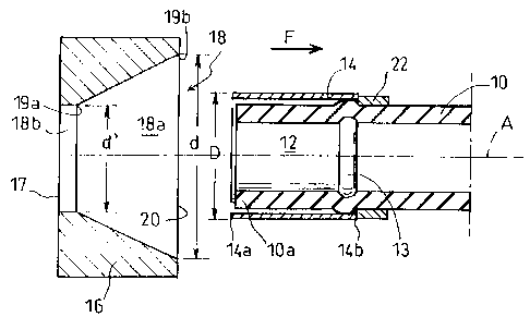
Figure 1 shows a flexible hose 10 whose free end l0a
is engaged on a rigid tubular element 12, while a
cylindrically-shaped ring 14 is engaged on the free end
10a.
To simplify the description below, it is assumed
that the end l0a is the front end of the flexible hose
10. Since the figures are truncated, its remote or rear
end is not shown.
In Figure 1, the ring 14 is shown prior to being
swaged, and its diameter D is greater than the diameter
of the hose 10.
Figure 1 also shows a swaging die 16 provided with
an axial cavity 18. The cavity has a flared length 18a
that flares from a first end 19a of diameter _d' and a
second end 19b of diameter _d. The diameter _d is greater
than the diameter D, which is itself greater than the
diameter _d'. Adjacent to the first end 19a of the flared
length, the cavity includes a cylindrical length 18b of
diameter _d' which opens out into a narrow open end 17.
At its other end, the cavity has a large open end which,
in the example shown, coincides with the second end 19b
of the flared length which is frustoconical.
Figure 1 shows these various elements immediately
before the beginning of the swaging process, in a
position where the axis of the cavity is in alignment
with the longitudinal axis A of the flexible hose, and
the large open end 20 is facing rearwards.
Figure 1 also shows a tool 22 for holding the ring
14 axially, with the rear end I4b of the ring coming into
- 2i787~~
6
abutment therewith. The tool is shown diagrammatically
only in Figure 1. It may comprise two haws that are
placed around the hose in such a manner as to co-operate
with the free end 14b of the ring 14 so as to hold it in
place during swaging.
To begin the swaging process, the swaging die is
placed in such a manner that at least the large end 20 of
the cavity is disposed around the ring to be swaged,
while the first end 19a is placed in front thereof,
beyond the front end of the hose. In other words, the
die is displaced relative to the swaging ring in the
direction of arrow F, i.e. going from the front end l0a
of the hose towards its rear end, or at least until the
end 20 of the cavity has come up to the front end 14a of
the ring.
Swaging proper begins when the wall of the cavity
starts to co-operate with the outer periphery of the
ring.
To perform swaging, as shown in Figures 2 and 3, the
swaging die 16 is displaced axially over the ring 14 in
the direction of arrow F, i.e. rearwards.
It will be understood that while such displacement
is taking place, since the ring is held in place by the
holding tool 22, its outside diameter is progressively
reduced down to the small diameter _d' of the cavity 18.
While this is taking place, progressive creep is being
applied to the end l0a of the flexible hose.
At the end of swaging, the configuration shown in
Figure 3 is reached in which the ring 14 is crimped on
the end l0a of the hose which is securely clamped between
the rigid tubular element 12 and the ring 14.
As can be seen in this figure, which shows the end
of swaging, the axial displacement of the swaging die 16
relative to the ring 14 is preferably stopped before the
smaller diameter end of the flared length 18a of the
cavity has reached the rear end 14b of the ring 14 that
is remote from the free end l0a of the hose 10. The rear
217740
7
end portion of the ring thus flares slightly and does not
run the risk of in uring the hose.
In addition, it can be seen in the figures that the
tubular element 12 has a radial swelling 13 in the
vicinity of its own rear end. Swaging is preferably
stopped before the ring has been totally swaged onto the
swelling. This ensures a reliable connection between the
elements of the coupling device while avoiding local
crushing of the hose against the swelling, which could
harm the mechanical qualities of the hose.
Once swaging has been completed, it suffices to
disengage the ring from the swaging die by displacing the
die in the direction opposite to arrow F, and to remove
the holding tool 22.
- In Figures 1 to 3, the cylindrical ring 14 is swaged
over substantially all of its length.
In some cases, as shown in Figures 4 and 5, it is
desirable to swage only a portion of the ring. in these
figures, elements analogous to those of Figures 1 to 3
are given the same reference numerals plus 100.
The ring 114 has a first portion 115a that is not to
be swaged. In the example shown, this portion 115a
extends forwards beyond the front end 110a of the
flexible hose 110 and can serve as a housing for a
sealing ring 117 or can be provided with a member for
fixing to a rigid tubular endpiece to which it is desired
to couple the hose 110.
It is thus only the rear portion 115b of the ring
114 that is to be swaged. The portion 115a constitutes
an axial obstacle that makes it possible to use a one
piece swaging die 16 under the conditions described above
with reference to Figures 1 to 3. A swaging die 116 is
therefore used which comprises two shells 116a and 116b.
To put this die into place around the ring, the
shells 116a and 116b are firstly moved apart from each
other so as to leave a passage that is large enough to
allow the ring to pass through, or more precisely to
~ 217814
8
allow the front portion 115a thereof to pass through.
Axial swaging proper, during which the die is displaced
in the direction of arrow F, begins after the two shells
have been moved together around the ring so as to cause
said passage to be eliminated.
Once the two shells have been assembled together in
this way, a die cavity 118 is defined that has a flared
length 118a and a smaller-diameter cylindrical length
ll8b.
The small end 121 of the cavity situated remote from
the large end 120 thereof is open. As can be seen in
Figure 5, this makes it possible to place the die 116
about the portion 115b to be swaged while leaving the
first portion 115a of the ring 114 projecting forwards
beyond the die.
The portion 115b is swaged by displacing the die 116
in the direction of arrow F, i.e. by causing it to go
from its start-of-swaging position shown in chain-dotted
lines to its end-of-swaging position shown in solid
lines. Throughout axial displacement of the swaging die,
the ring is held axially by means of a swaging tool 122.
In the example shown in Figures 4 and 5, the tool 122
comprises jaws that co-operate with the front portion of
the ring 114. More precisely, the jaws of the tool 122
are placed around the ring immediately behind the first
portion 115 thereof, and come into abutment against a
shoulder 114' so as to hold the ring and prevent it from
being displaced rearwards during swaging.
In Figure 4, it can be seen that all of the second
portion 115b situated behind the first portion 115a of
the ring has a diameter, prior to swaging, that is
greater than the diameter to which it is to be reduced by
swaging. This applies in particular to the front end
region 115c of the portion 115b which is situated
directly behind the first portion 115a. As a result,
when the shells are moved towards each other about the
ring 114, prior to the die being displaced axially, a
217~~'40
9
preliminary step of radial swaging is performed in this
region 115c, over a small fraction of the length of the
portion that is to be swaged.
Preferably, as can be seen in Figures 4 and 5, the
region 115c in which the preliminary step of radial
swaging is performed extends forwards beyond the front
end 110a of the flexible hose so that any drawbacks that
may be associated with this operation of radial swaging
have no effect on the hose.
It is also possible for the diameter of the
intermediate portion 115c to be initially smaller than or
equal to the swaging diameter, in which case there is no
need for a preliminary radial swaging step.
Although the ring is held axially and the die is
displaced in the direction of arrow F in the examples
shown in the figures, it should be observed that it would
be equally possible to perform swaging by holding the die
axially and displacing the ring in the opposite direction
to arrow F. The important point is that the two elements
constituted by the ring and the die are displaced
relative to each other with the die moving in the
direction of arrow F, i.e. rearwards, along the portion
to be swaged.