Sélection de la langue

Search

Sommaire du brevet 2178886 

Énoncé de désistement de responsabilité concernant l'information provenant de tiers

Une partie des informations de ce site Web a été fournie par des sources externes. Le gouvernement du Canada n'assume aucune responsabilité concernant la précision, l'actualité ou la fiabilité des informations fournies par les sources externes. Les utilisateurs qui désirent employer cette information devraient consulter directement la source des informations. Le contenu fourni par les sources externes n'est pas assujetti aux exigences sur les langues officielles, la protection des renseignements personnels et l'accessibilité.

Disponibilité de l'Abrégé et des Revendications

L'apparition de différences dans le texte et l'image des Revendications et de l'Abrégé dépend du moment auquel le document est publié. Les textes des Revendications et de l'Abrégé sont affichés :

  • lorsque la demande peut être examinée par le public;
  • lorsque le brevet est émis (délivrance).
(12) Demande de brevet: (11) CA 2178886
(54) Titre français: PANNEAUX EN BETON AVEC GARNITURES EN ELASTOMERE INCORPOREES POUR PASSAGES A NIVEAU
(54) Titre anglais: CONCRETE GRADE CROSSING PANELS HAVING INTEGRAL ELASTOMERIC SEALS
Statut: Réputée abandonnée et au-delà du délai pour le rétablissement - en attente de la réponse à l’avis de communication rejetée
Données bibliographiques
(51) Classification internationale des brevets (CIB):
  • E01B 07/28 (2006.01)
  • E01B 02/00 (2006.01)
  • E01B 21/00 (2006.01)
  • E01C 09/04 (2006.01)
(72) Inventeurs :
  • WILLIAMS, JACK (Etats-Unis d'Amérique)
(73) Titulaires :
  • OMNI PRODUCTS, INC.
(71) Demandeurs :
  • OMNI PRODUCTS, INC. (Etats-Unis d'Amérique)
(74) Agent: OYEN WIGGS GREEN & MUTALA LLP
(74) Co-agent:
(45) Délivré:
(22) Date de dépôt: 1996-06-12
(41) Mise à la disponibilité du public: 1997-01-06
Requête d'examen: 1996-06-12
Licence disponible: S.O.
Cédé au domaine public: S.O.
(25) Langue des documents déposés: Anglais

Traité de coopération en matière de brevets (PCT): Non

(30) Données de priorité de la demande:
Numéro de la demande Pays / territoire Date
08/498,600 (Etats-Unis d'Amérique) 1995-07-05

Abrégés

Abrégé anglais


A rail grade crossing includes precast concrete
panels which extend substantially between the roadway and
the rails and between the rails. Elastomeric seals that
are cast into the panels when they are formed fit between
the panels and the rails. Because the seals are cast
into the panels, the panels and seals are an integral
unit which facilitates installation and removal of the
panels.

Revendications

Note : Les revendications sont présentées dans la langue officielle dans laquelle elles ont été soumises.


What is Claimed is:
1. A railroad grade crossing for extending a
paved roadway across a pair of parallel, spaced apart
rails, comprising:
(a) a concrete gauge panel that extends
substantially between the rails and has a
planar top surface that is coplanar with
the roadway;
(b) said gauge panel having elastomeric gauge
seals on each side thereof which are adja-
cent to the rails when said gauge panel is
located therebetween;
(c) a pair of concrete field panels, one of
which extends substantially between each
rail and the roadway, having planar top
surfaces that are coplanar with the
roadway;
(d) said field panels each having an
elastomeric field seal on one side
thereof, which is adjacent to the respec-
tive rail when said field panel is located
between the rail and the roadway; wherein
(e) said seals are cast into said panels to
form integral panel/seal units.
2. The grade crossing of claim 1 wherein each
seal comprises a first face that is adjacent to the
respective panel, an opposed second face that is adjacent
to the respective rail, and a ledge that projects from
said first face and is imbedded in the respective panel.
3. The grade crossing of claim 2 wherein said
ledge has a substantially vertical lip.

4. The grade crossing of claim 2 wherein said
field seal has a planar upper face that is offset
slightly downward from the top surface of said field
panel.
5. The grade crossing of claim 2 wherein said
gauge seals have planar upper faces that are offset
slightly downwardly from the top surface of said gauge
panel, and recessed portions between said upper faces and
the respective rail.

Description

Note : Les descriptions sont présentées dans la langue officielle dans laquelle elles ont été soumises.

r
21'7888
CONCRETE GRADE CROSSING PANELS
HAVING INTEGRAL ELASTOMERIC SEALS
Background and Summary of the Invention
This invention relates to railroad grade
crossings, and in particular to railroad grade crossings
incorporating precast concrete panels with elastomeric
seals between the panels and the rails.
When a railroad track crosses a roadway it is
necessary to bring the space between the roadway and the
rails, and the space between the rails, up to grade.
This is accomplished by installing grade crossing
elements into these spaces. In busy city streets it has
become common to use precast Concrete panels for this
purpose. Concrete panels wear well and, therefore, with-
stand the heavy traffic occurring on busy city streets.
In addition, precast concrete panels are quickly
installed which reduces the time the street is unavail-
able during installation of the crossing. Finally,
precast concrete panels are easily and quickly removed to
access the track for repairs and maintenance.
When precast concrete crossing panels are used
it is desirable to place elastomeric seals between the
panels and the rails. These seals provide a positive
flangeway which prevents water from getting beneath the
panels and weakening the ballast. The seals also create
a cushioning transition between the rails and the
concrete panels, which makes for a smoother ride for
vehicles crossing the tracks and prevents chipping of the
corners of the panels. The seals also reduce the trans-
mission of vibration from the rails to the panels.
Finally, elastomeric seals electrically isolate the rails
from the panels. Precast concrete grade crossing panels
with elastomeric seals are shown, for example, in Davis,
U.S. Patent 5,181,657 and Martin, U.S. Patent 4,899,933.
With both of these prior art crossing systems
the seal and concrete panels are separate elements. In

. ~
2178886
Davis, the seal is partially overlaid by the panel, andthe panel holds the seal in place. In Martin, the seal
is inserted between the panel and the rail after the
panel is installed. In either case, the seal complicates
installation of the grade crossing, and with Martin the
seal can become dislodged in use.
The subject invention overcomes this problem
with the prior art precast concrete panel/elastomeric
seal grade crossing systems by casting the seals into the
panels to form integral panel seal units. In a preferred
embodiment of the invention, the seal has a ledge with an
downwardly projecting lip that is imbedded in the
concrete panel.
The foregoing and other objectives, features,
and advantages of the invention will be more readily
understood upon consideration of the following detailed
description of the invention, taken in conjunction with
the accompanying drawings.
~rief DescriPtion of the Drawinqs
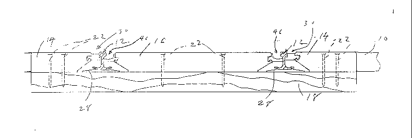
FIG. 1 is a fragmentary plan view, partially
broken away, of a railroad grade crossing embodying the
subject invention.
FIG. 2 is a sectional view taken along line 2-2
in FIG. 1.
FIG. 3 is a detailed view, at an enlarged
scale, showing how the seals in the grade crossing are
embedded in the concrete pad and interact with the rails.
FIG. 4 is a detailed view, at an enlarged
scale, showing a rib which is embedded in the concrete
pad.
Detailed Description of the Preferred Embodiment
Referring to the drawings, when a railroad
track crosses a roadway 10, a grade crossing must be
installed that fills the open spaces between the roadway
and the rails 12 and between the rails. This is

2178886
accomplished in the subject invention by placing a
precast concrete gauge panel 14 between the rails, and
precast concrete field panels 16 between each rail and
the edge of the roadway 10. These panels rest on the
timber or concrete ties 18 that support the rails, and
are held in place in the conventional manner. The panels
have a thickness which makes their top surfaces coplanar
with the roadway, and with the tops of the rails. In the
embodiment shown in the drawings, the panels are shown
with wood ties and they have counterbored holes 20
located in them and timber screws 22 are inserted through
these holes and into the ties to secure the panels to the
ties. The panels also may have lifting eye pockets 24
placed in them to receive lifting hooks (not shown) to
facilitate lifting the panels when they are being
installed or removed. Precast concrete grade crossing
panels in general are well known in the prior art, and
are shown in Davis, U.S. Patent 5,181,657, and Martin,
U.S. Patent 4,899,933.
The outer sides of the field panels 14 abut the
roadway 10, although an expansion joint may be inserted
between them. The inner sides of the field panels and
both sides of the gauge panel are spaced apart from the
adjacent rail and are undercut to fit over the tie plates
28 that are used to attach the rails to the ties.
Referring now particularly to FIG. 3, located
on the inner side of each field panel 14 is an elasto-
meric field seal 30 which spans between the field panel
and the rail. The field seal 30 has a first side 32 that
abuts the field panel 14 and a second side 34 that abuts
the head 36 of the rail 12 and may or may not abut the
rail web 52. The field seal also has a planar upper face
38 which is offset slightly downward from the top surface
of the field panel 14, and a lower face 40 which is
located above the fasteners 43 that attach the rails to
the ties. Each field seal has a ledge 42 protruding from
its first side 32 that is cast into the field panel when

21788~6
- 4
the field panel is formed. Thus, the field seal and the
field panel form an integral unit. The ledge 42 has an
downwardly extending lip 44 that assists it in bonding to
the field panel.
Located on both sides of each gauge panel 16 is
an elastomeric gauge seal 46 which spans between the
gauge panel and the rail. The gauge seal 46 has a first
side 48 that abuts the gauge panel and a second side 50
that fits under the rail head 36 and may or may not abut
the rail web 52. The gauge seal also has a short planar
upper face 54 which is offset slightly downward from the
top surface of the gauge panel, and a lower face 56 which
is located above the fasteners 43. A recess 58 extends
between the upper face 54 and the second side to accommo-
date the wheel flange (not shown) of rail cars travelingon the tracks. The gauge seal has a ledge 60 protruding
from its first side 48 that is cast into the gauge panel
when it is formed. Thus, the gauge panel and gauge seals
form an integral unit. The ledge 60 has an downwardly
projecting lip 62 that assists it in bonding to the gauge
panel. The gauge seal also has a series of spaced-part
trapezoidal ribs 61 that project from its first side 48
above the ledge 60. The ribs also are cast into the
concrete, and prevent the first side of the gauge seal
~ 25 from pulling away from the gauge panel when traffic
passes over the crossing. If the first side of the gauge
seal were to pull away from the gauge panel, material
could drop between them and create a permanent
separation.
The edges of both the gauge and field panels
are chamfered to prevent them from becoming chipped by
vehicles crossing over them. The chamfer on the sides of
the panels that abut the respective seals has a depth
which is equal to the amount the upper face of the seal
is offset from the top surface of the panel.

~ . ~
` 2178886
- 5
Because the seals are integral with the panels
installation and removal of the panels is greatly
simplified, and the seals cannot become dislodged in use.
The terms and expressions which have been
employed in the foregoing specification are used therein
as terms of description and not of limitation, and there
is no intention, in the use of such terms and expres-
sions, of excluding equivalents of the features shown and
described or portions thereof, it being recognized that
the scope of the invention is defined and limited only by
the claims which follow.

Dessin représentatif
Une figure unique qui représente un dessin illustrant l'invention.
États administratifs

2024-08-01 : Dans le cadre de la transition vers les Brevets de nouvelle génération (BNG), la base de données sur les brevets canadiens (BDBC) contient désormais un Historique d'événement plus détaillé, qui reproduit le Journal des événements de notre nouvelle solution interne.

Veuillez noter que les événements débutant par « Inactive : » se réfèrent à des événements qui ne sont plus utilisés dans notre nouvelle solution interne.

Pour une meilleure compréhension de l'état de la demande ou brevet qui figure sur cette page, la rubrique Mise en garde , et les descriptions de Brevet , Historique d'événement , Taxes périodiques et Historique des paiements devraient être consultées.

Historique d'événement

Description Date
Inactive : CIB de MCD 2006-03-12
Demande non rétablie avant l'échéance 1999-12-09
Inactive : Morte - Aucune rép. dem. par.30(2) Règles 1999-12-09
Réputée abandonnée - omission de répondre à un avis sur les taxes pour le maintien en état 1999-06-14
Inactive : Abandon. - Aucune rép dem par.30(2) Règles 1998-12-09
Inactive : Dem. de l'examinateur par.30(2) Règles 1998-06-09
Inactive : Renseign. sur l'état - Complets dès date d'ent. journ. 1998-03-24
Inactive : Dem. traitée sur TS dès date d'ent. journal 1998-03-24
Demande publiée (accessible au public) 1997-01-06
Toutes les exigences pour l'examen - jugée conforme 1996-06-12
Exigences pour une requête d'examen - jugée conforme 1996-06-12

Historique d'abandonnement

Date d'abandonnement Raison Date de rétablissement
1999-06-14

Taxes périodiques

Le dernier paiement a été reçu le 1998-05-25

Avis : Si le paiement en totalité n'a pas été reçu au plus tard à la date indiquée, une taxe supplémentaire peut être imposée, soit une des taxes suivantes :

  • taxe de rétablissement ;
  • taxe pour paiement en souffrance ; ou
  • taxe additionnelle pour le renversement d'une péremption réputée.

Les taxes sur les brevets sont ajustées au 1er janvier de chaque année. Les montants ci-dessus sont les montants actuels s'ils sont reçus au plus tard le 31 décembre de l'année en cours.
Veuillez vous référer à la page web des taxes sur les brevets de l'OPIC pour voir tous les montants actuels des taxes.

Historique des taxes

Type de taxes Anniversaire Échéance Date payée
Requête d'examen - générale 1996-06-12
TM (demande, 2e anniv.) - générale 02 1998-06-12 1998-05-25
Titulaires au dossier

Les titulaires actuels et antérieures au dossier sont affichés en ordre alphabétique.

Titulaires actuels au dossier
OMNI PRODUCTS, INC.
Titulaires antérieures au dossier
JACK WILLIAMS
Les propriétaires antérieurs qui ne figurent pas dans la liste des « Propriétaires au dossier » apparaîtront dans d'autres documents au dossier.
Documents

Pour visionner les fichiers sélectionnés, entrer le code reCAPTCHA :


Pour visualiser une image, cliquer sur un lien dans la colonne description du document (Temporairement non-disponible). Pour télécharger l'image (les images), cliquer l'une ou plusieurs cases à cocher dans la première colonne et ensuite cliquer sur le bouton "Télécharger sélection en format PDF (archive Zip)" ou le bouton "Télécharger sélection (en un fichier PDF fusionné)".

Liste des documents de brevet publiés et non publiés sur la BDBC .

Si vous avez des difficultés à accéder au contenu, veuillez communiquer avec le Centre de services à la clientèle au 1-866-997-1936, ou envoyer un courriel au Centre de service à la clientèle de l'OPIC.

({010=Tous les documents, 020=Au moment du dépôt, 030=Au moment de la mise à la disponibilité du public, 040=À la délivrance, 050=Examen, 060=Correspondance reçue, 070=Divers, 080=Correspondance envoyée, 090=Paiement})


Description du
Document 
Date
(aaaa-mm-jj) 
Nombre de pages   Taille de l'image (Ko) 
Abrégé 1996-09-29 1 14
Description 1996-09-29 5 212
Revendications 1996-09-29 2 49
Dessins 1996-09-29 2 57
Revendications 1997-01-16 2 49
Abrégé 1997-01-16 1 14
Description 1997-01-16 5 212
Dessins 1997-01-16 2 57
Dessin représentatif 1997-10-27 1 11
Rappel de taxe de maintien due 1998-02-15 1 111
Courtoisie - Lettre d'abandon (R30(2)) 1999-02-02 1 171
Courtoisie - Lettre d'abandon (taxe de maintien en état) 1999-07-11 1 186