Sélection de la langue

Search

Sommaire du brevet 2178980 

Énoncé de désistement de responsabilité concernant l'information provenant de tiers

Une partie des informations de ce site Web a été fournie par des sources externes. Le gouvernement du Canada n'assume aucune responsabilité concernant la précision, l'actualité ou la fiabilité des informations fournies par les sources externes. Les utilisateurs qui désirent employer cette information devraient consulter directement la source des informations. Le contenu fourni par les sources externes n'est pas assujetti aux exigences sur les langues officielles, la protection des renseignements personnels et l'accessibilité.

Disponibilité de l'Abrégé et des Revendications

L'apparition de différences dans le texte et l'image des Revendications et de l'Abrégé dépend du moment auquel le document est publié. Les textes des Revendications et de l'Abrégé sont affichés :

  • lorsque la demande peut être examinée par le public;
  • lorsque le brevet est émis (délivrance).
(12) Brevet: (11) CA 2178980
(54) Titre français: COMMANDE ELECTROHYDRAULIQUE DE FREIN DE STATIONNEMENT SERVANT A EVITER LE SERRAGE DU FREIN LORSQUE LE VEHICULE EST EN MOUVEMENT
(54) Titre anglais: ELECTROHYDRAULIC PARKING BRAKE CONTROL SYSTEM FOR PREVENTING BRAKE ENGAGEMENT WHEN VEHICLE IS IN MOTION
Statut: Périmé et au-delà du délai pour l’annulation
Données bibliographiques
(51) Classification internationale des brevets (CIB):
  • B60T 13/68 (2006.01)
  • B60T 13/22 (2006.01)
(72) Inventeurs :
  • BEBERNES, THOMAS DARYL (Etats-Unis d'Amérique)
(73) Titulaires :
  • DEERE & COMPANY
(71) Demandeurs :
  • DEERE & COMPANY (Etats-Unis d'Amérique)
(74) Agent: BORDEN LADNER GERVAIS LLP
(74) Co-agent:
(45) Délivré: 2000-08-22
(22) Date de dépôt: 1996-06-14
(41) Mise à la disponibilité du public: 1997-05-30
Requête d'examen: 1996-06-14
Licence disponible: S.O.
Cédé au domaine public: S.O.
(25) Langue des documents déposés: Anglais

Traité de coopération en matière de brevets (PCT): Non

(30) Données de priorité de la demande:
Numéro de la demande Pays / territoire Date
08/564,530 (Etats-Unis d'Amérique) 1995-11-29

Abrégés

Abrégé français

Un véhicule possède un système de frein de stationnement comprenant des freins à ressort à détente de pression. Il est prévu un système de commande électrohydraulique destiné à apporter de l'énergie à une valve de frein à commande par solénoïde de manière que de la pression de détente soit fournie aux freins lorsque le levier de commande de transmission est au neutre ou que le tachymètre du véhicule indique une vitesse par rapport au sol autre que zéro.


Abrégé anglais

A vehicle has a parking brake system including spring-applied, pressure- released brakes. An electrohydraulic control system is provided for selectively energizing a solenoid-operated brake control valve so that release pressure is supplied to the brakes when the transmission control lever is not in neutral or when the vehicle tachometer is indicating a ground speed other than zero.

Revendications

Note : Les revendications sont présentées dans la langue officielle dans laquelle elles ont été soumises.


The embodiments of the invention in which an exclusive property or privilege
is
claimed are defined as follows:
1. A parking brake system including at least one spring-applied,
hydraulic pressure-released brake having a pressure chamber for receiving
release-pressure fluid; a source of fluid pressure; a sump; a parking brake
control valve
coupled to said chamber, source of fluid pressure and sump and being movable
between
brake-engage and brake-release positions respectively coupling said chamber to
said sump
and source of fluid pressure; said control valve including a spring biasing
the valve to said
brake-engage position and a solenoid energizable for moving the valve to said
brake-release
position; an electrohydraulic control for said parking brake control valve
comprising: an
electric power source; a transmission shift lever moveable among a neutral
position and
various forward or reverse positions; a parking brake relay switch including a
first switching
element coupled to said power source, a first contact coupled to said solenoid
and a first coil
energizable for connecting said first switching element to said first contact
for completing a
circuit to said solenoid; a neutral switch having a second switching element
connected to
said power source and a first "on" contact connected to said first coil with
said second
switching element being operatively connected to said shift lever so as to be
moved to
engage said "on" contact to complete a circuit to said first coil whenever
said lever is not in
said neutral position; a vehicle ground speed sensing device for generating an
electrical
signal representative of ground speed; a ground speed relay switch having a
second coil
connected to said power source, having a third switching element connected to
said first coil
and having a second "on" contact connected to said power source; a ground
speed signal
processing means connected to said ground speed sensing device and to said
second coil
and including means responsive to said electrical signal for establishing a
completed circuit
through said second coil only if said ground speed signal represents a speed
above a
predetermined minimum speed, whereby said brake control valve will ensure that
the brake
remains disengaged even if the transmission shift lever is in its neutral
position so long as
the ground speed remains above said predetermined minimum speed.
2. The parking brake system defined in claim 1 wherein said ground speed
signal processing means is a tachometer.
3. The parking brake system defined in claim 1 wherein said predetermined
minimum speed is zero.
4. An electrohydraulic parking brake control system, comprising: at least one
spring-applied, pressure-released parking brake including a control pressure
chamber; an
engine-driven pump for supplying release-pressure; a sump; a parking brake
control valve
connected to the pump, sump and pressure chamber and including a spring
biasing the
valve to a normal brake-engage position connecting the control pressure
chamber of the

parking brake to the sump and including a solenoid which, when actuated, acts
to shift the
control valve to an actuated brake-release position connecting said control
pressure
chamber to the pump; a transmission controller movable among a neutral and
various
forward and reverse speed positions; an electric power source; a neutral
switch operatively
associated with said transmission controller and movable between an open
position, which it
occupies when the transmission controller is in its neutral position, and a
closed position in
response to said transmission controller being removed from its neutral
position; a first
electrical relay switch means coupled to said electric power source, said
neutral switch and
said solenoid of the parking brake control valve and being switched when
energized, in
response to said neutral switch being placed in its closed position, for
completing a circuit to
said solenoid to thereby shift the valve to connect release pressure to said
brake control
pressure chamber when the transmission controller is removed from its neutral
position; a
vehicle ground speed monitoring means; a second electrical relay switch means
coupled to
said vehicle ground speed monitoring means, said electric power source and
said first
electrical relay switch means; said ground speed monitoring means being
responsive to
ground speeds above a predetermined minimum ground speed for establishing a
circuit
energizing said second electrical relay switch means; and said second
electrical relay switch
means, when energized, completing a circuit for energizing said first
electrical relay switch
means independent of said neutral switch, whereby said solenoid of said
parking brake
control valve will be energized to shift said valve to connect release-
pressure to said control
pressure chamber anytime the vehicle ground speed exceeds said predetermined
minimum
ground.
5. The electrohydraulic parking brake control system defined in claim 4
wherein
said predetermined minimum ground speed is zero.
6. The electrohydraulic parking brake control system defined in claim 4
wherein
said ground speed monitoring means includes a speed sensing means for sensing
ground
speed and producing an electrical signal representative of the ground speed,
and a signal
processing means including a switching means coupled in series between said
second relay
switch means and ground for establishing a ground connection for said second
relay switch
means resulting in the energization of said second relay switch means when
said electrical
signal is of a value greater than that representative of said predetermined
minimum speed.
7. The electrohydraulic parking brake control system defined in claim 6
wherein
said signal processing means is a digital tachometer.
2

Description

Note : Les descriptions sont présentées dans la langue officielle dans laquelle elles ont été soumises.

2 1 78980
.
ELECTROHYDRAULIC PARKING BRAKE CONTROL SYSTEM FOR
PREVENTING BRAKE ENGAGEMENT WHEN VEHICLE IS IN MOTION
Background of the Invention
The present invention relates to vehicle parking brakes and more
specifically relates to a system for controlling spring-applied, hydraulically released
parking brakes.
A known self-propelled agricultural vehicle has a pair of driven ground
wheels and is equipped with a braking system including a pair of lever-actuated
parking brakes respectively associated with the pair of driven ground wheels.
While operators are instructed to set or engage the parking brakes when the
vehicle is parked, such action is not always taken creating the hazard of the
vehicle possibly rolling unattended and causing property damage and/or physical
injury. Interlocks are commonly provided, however, for preventing the vehicle
engine from being started unless the parking brake lever is first placed in its
brake-engage position.
In order to eliminate the problem of operators forgetting or neglecting to set
or engage the parking brakes when parking a vehicle, it is known to automate this
function by providing vehicles with parking brakes that are spring-engaged and
hydraulic pressure-released. The source of fluid pressure for disengaging these
brakes is usually provided by an engine-driven pump so that any time the engine
is shut down the brakes are automatically engaged. These systems also include
an interlock with the vehicle transmission shift lever which results in the brakes
being automatically engaged any time the shift lever is moved to its "neutral"
position. Thus, the parking brakes are set any time the vehicle is parked with the
transmission in neutral and the engine running. Because it is possible that the
vehicle may be rolling when the transmission shift lever is placed in its "neutral"
position, the known brake system includes an auxiliary ground wheel driven pump
that provides sufficient fluid pressure to keep the brakes disengaged until the
vehicle has slowed to a predetermined speed. Such a braking system is
disclosed in U.S. Patent No. 5,203,616 granted to Douglas Johnson on 20 April
1 993.
A drawback of the patented system is that the components used for
preventing brake engagement when the vehicle speed is excessive for braking add

2 1 78980
-
a significant cost to the system, and engagement of the brakes at even a slow
speed has been found to result in jerking which is uncomfortable to the operator.
Summary of the Invention
According to the present invention there is provided an improved control
5 system for spring-applied, pressure-released parking brakes.
A broad object of the invention is to provide a parking brake control system
for automating the engagement of the parking brakes to ensure that the brakes will
be engaged whenever the vehicle is parked with or without the engine running,
while preventing the brakes to be engaged so long as the vehicle is in motion.
A more specific object of the invention is to provide an electrohydraulic
control system which incorporates the vehicle tachometer, the tachometer acting
to complete a circuit for actuating a solenoid-operated parking brake control valve
so that pressure is supplied to keep the brakes released whenever the vehicle
ground speed indicated by the tachometer is other than zero.
These and other objects will become apparent from a reading of the
ensuing description together with the appended drawing.
Brief Description of the Drawing
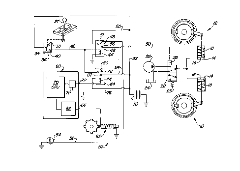
The sole FIGURE is a schematic diagram of an electrohydraulic control
system for controlling the operation of spring-applied, pressure-released parking
20 brakes.
Description of the Preferred Embodiment
Referring to the drawing, there is shown a parking brake system including
identical right- and left-hand parking brakes 10 and 12, respectively, each
including a piston 14 slidably mounted in a cylinder with a release-pressure
25 chamber 16 located at one side, and with a brake-engaging spring 18 located at
another side, of the piston.
An electrohydraulic control system 20 is provided for controlling the flow of
brake-release pressure fluid to and from the release-pressure chambers 16.
Specifically, the control system 20 includes a solenoid-operated, two-position
30 brake control valve 22 movable between a brake-engage position, as shown, to
which it is biased by a biasing spring 23 and in which it couples the release-
pressure chambers 16 to a sump 24 while blocking them from pressure supplied

2 1 789~0
by an engine-driven, release-pressure supply pump 26. An electrical circuit for
selectively supplying power to a solenoid 28 of the brake control valve 22 includes
a power source, here shown as a battery 30. A power supply lead 32 is
connected between the battery 30 and a switch element 34 of a transmission
neutral switch 36, the latter being positioned so that a transmission control lever
37 engages and moves the element 34 against an "of~' or "neutral" contact 38, asshown, only when the lever is in its "neutral" position. The neutral switch 36 also
includes an "on" or "not neutral" contact 40. A lead 42 is connected between the"on" contact 40 and a grounded relay coil 44 of a parking brake relay switch 46,the latter having a switching element 48 connected to the power supply lead 32 by
a branch lead 50. When the relay coil 44, and hence the switch 46, is
deactivated, the switch element 48 is connected to a first relay contact 51, as
shown, which is connected by a lead 52 to a grounded brake light 54. The relay
switch 46 includes a second relay contact 56 connected, by a lead 58, to the
solenoid 28 of the brake control valve 22.
Thus, when the transmission control lever is not in its "neutral" position, the
switch element 34 of the neutral switch 36 will be in contact with the "on" contact
40 so as to complete a power circuit to energize the relay coil 44 and cause it to
pull the switching element 48 into engagement with the second relay contact 56 so
as to complete a power circuit to the valve solenoid 28. The actuated solenoid 28
will cause the brake control valve 22 to be shifted, against the bias of the spring
23, to its brake-release position coupling the pump 26 in fluid communication with
the release-pressure chambers 16 of the cylinders of the parking brakes 10 and
12.
To keep the parking brakes 10 and 12 from being set even when the
transmission control lever is in its "neutral" position, if the vehicle ground speed is
greater than a preselected minimum speed, a ground speed signal processing
device in the form of a digital tachometer 60, a ground speed sensing device 62
and a tachometer output or ground speed relay switch 64 are coupled in the
control circuit. Specifically, the tachometer 60 includes a port 66 coupled to the
ground speed sensing device 62 which generates and sends the tachometer an
electrical signal representative of the vehicle ground speed. The tachometer 60

21 78980
-
contains a signal-shaping circuit 68 coupled to the port 66 that is in turn coupled
to a central processing unit (CPU) 70 having an output connected to a grounding
switch 71, the CPU 70 being programmed to send a signal to the grounding switch
70 to cause the latter to connect a port 72 to ground in the event the ground
speed is above a preselected minimum value (U.S. Patent No. 4,281,388 granted
to Friend et al on 28 July 1981 discloses a tachometer having a signal-shaping
circuit and CPU). The preselected ground speed value is preferably zero but may
be some small amount greater than zero. In any event, the second port 72 is
coupled to a ground side of a coil 74 of the tachometer output relay switch 64, the
power side of the coil being coupled to the power supply lead 32 by a branch lead
76. The relay switch 64 includes a switching element 78 that is normally coupledto an "off" contact 80 when the coil 74 is de-energized, as shown. When the
vehicle is in motion, the coil 74 will be energized causing the switching element 78
to be pulled into engagement with an "on" contact 82 which is connected to the
power supply lead 32 by a branch lead 84.
Accordingly, when the transmission neutral switch 36 is in its "off" or
"neutral" position, as shown, engagement of the parking brakes 10 and 12 will beprevented if the vehicle is rolling since this movement will be sensed by the speed
sensing device 62 which will generate and send a signal to the tachometer 60, the
latter acting to process the signal and to effect actuation of the switch 71 to
connect the coil 74 to ground resulting in the coil being energized causing the
switching element 78 of tachometer output relay switch 64 to be moved to
complete a circuit energizing the coil 44 of the parking brake relay switch 46
resulting in its switching element 48 being moved to establish a circuit through the
brake control valve solenoid 28. The brake control valve 22 then shifts to its
brake-release position coupling the pump 26 to the release-pressure chambers 16
so that the parking brakes remain disengaged. This assures that, in the case
where the transmission is a dual-path hydrostatic transmission, the hydrostatic
pumps are completely destroked so they do not push against the brakes, and also
assures that the vehicle is completely stopped before the brakes are applied so as
to prevent uncomfortable jerking and unnecessary loads to the brake components.

Dessin représentatif
Une figure unique qui représente un dessin illustrant l'invention.
États administratifs

2024-08-01 : Dans le cadre de la transition vers les Brevets de nouvelle génération (BNG), la base de données sur les brevets canadiens (BDBC) contient désormais un Historique d'événement plus détaillé, qui reproduit le Journal des événements de notre nouvelle solution interne.

Veuillez noter que les événements débutant par « Inactive : » se réfèrent à des événements qui ne sont plus utilisés dans notre nouvelle solution interne.

Pour une meilleure compréhension de l'état de la demande ou brevet qui figure sur cette page, la rubrique Mise en garde , et les descriptions de Brevet , Historique d'événement , Taxes périodiques et Historique des paiements devraient être consultées.

Historique d'événement

Description Date
Le délai pour l'annulation est expiré 2016-06-14
Lettre envoyée 2015-06-15
Inactive : CIB de MCD 2006-03-12
Accordé par délivrance 2000-08-22
Inactive : Page couverture publiée 2000-08-21
Inactive : Taxe finale reçue 2000-05-03
Préoctroi 2000-05-03
Un avis d'acceptation est envoyé 1999-12-17
Lettre envoyée 1999-12-17
Inactive : Approuvée aux fins d'acceptation (AFA) 1999-11-15
Modification reçue - modification volontaire 1999-09-21
Inactive : Dem. de l'examinateur par.30(2) Règles 1999-03-23
Inactive : Renseign. sur l'état - Complets dès date d'ent. journ. 1998-09-03
Inactive : Dem. traitée sur TS dès date d'ent. journal 1998-09-03
Demande publiée (accessible au public) 1997-05-30
Toutes les exigences pour l'examen - jugée conforme 1996-06-14
Exigences pour une requête d'examen - jugée conforme 1996-06-14

Historique d'abandonnement

Il n'y a pas d'historique d'abandonnement

Taxes périodiques

Le dernier paiement a été reçu le 2000-06-13

Avis : Si le paiement en totalité n'a pas été reçu au plus tard à la date indiquée, une taxe supplémentaire peut être imposée, soit une des taxes suivantes :

  • taxe de rétablissement ;
  • taxe pour paiement en souffrance ; ou
  • taxe additionnelle pour le renversement d'une péremption réputée.

Les taxes sur les brevets sont ajustées au 1er janvier de chaque année. Les montants ci-dessus sont les montants actuels s'ils sont reçus au plus tard le 31 décembre de l'année en cours.
Veuillez vous référer à la page web des taxes sur les brevets de l'OPIC pour voir tous les montants actuels des taxes.

Titulaires au dossier

Les titulaires actuels et antérieures au dossier sont affichés en ordre alphabétique.

Titulaires actuels au dossier
DEERE & COMPANY
Titulaires antérieures au dossier
THOMAS DARYL BEBERNES
Les propriétaires antérieurs qui ne figurent pas dans la liste des « Propriétaires au dossier » apparaîtront dans d'autres documents au dossier.
Documents

Pour visionner les fichiers sélectionnés, entrer le code reCAPTCHA :


Pour visualiser une image, cliquer sur un lien dans la colonne description du document (Temporairement non-disponible). Pour télécharger l'image (les images), cliquer l'une ou plusieurs cases à cocher dans la première colonne et ensuite cliquer sur le bouton "Télécharger sélection en format PDF (archive Zip)" ou le bouton "Télécharger sélection (en un fichier PDF fusionné)".

Liste des documents de brevet publiés et non publiés sur la BDBC .

Si vous avez des difficultés à accéder au contenu, veuillez communiquer avec le Centre de services à la clientèle au 1-866-997-1936, ou envoyer un courriel au Centre de service à la clientèle de l'OPIC.

({010=Tous les documents, 020=Au moment du dépôt, 030=Au moment de la mise à la disponibilité du public, 040=À la délivrance, 050=Examen, 060=Correspondance reçue, 070=Divers, 080=Correspondance envoyée, 090=Paiement})


Description du
Document 
Date
(aaaa-mm-jj) 
Nombre de pages   Taille de l'image (Ko) 
Revendications 1999-09-20 2 134
Abrégé 1996-09-23 1 14
Description 1996-09-23 4 221
Revendications 1996-09-23 3 138
Dessins 1996-09-23 1 24
Revendications 1998-09-15 3 162
Dessin représentatif 2000-08-10 1 12
Dessin représentatif 1997-11-16 1 23
Rappel de taxe de maintien due 1998-02-16 1 111
Avis du commissaire - Demande jugée acceptable 1999-12-16 1 164
Avis concernant la taxe de maintien 2015-07-26 1 171
Correspondance 2000-05-02 1 30