Sélection de la langue

Search

Sommaire du brevet 2179142 

Énoncé de désistement de responsabilité concernant l'information provenant de tiers

Une partie des informations de ce site Web a été fournie par des sources externes. Le gouvernement du Canada n'assume aucune responsabilité concernant la précision, l'actualité ou la fiabilité des informations fournies par les sources externes. Les utilisateurs qui désirent employer cette information devraient consulter directement la source des informations. Le contenu fourni par les sources externes n'est pas assujetti aux exigences sur les langues officielles, la protection des renseignements personnels et l'accessibilité.

Disponibilité de l'Abrégé et des Revendications

L'apparition de différences dans le texte et l'image des Revendications et de l'Abrégé dépend du moment auquel le document est publié. Les textes des Revendications et de l'Abrégé sont affichés :

  • lorsque la demande peut être examinée par le public;
  • lorsque le brevet est émis (délivrance).
(12) Brevet: (11) CA 2179142
(54) Titre français: MACHINE POUR LA STABILISATION DE VOIES FERREES
(54) Titre anglais: MACHINE FOR STABILIZING A TRACK
Statut: Périmé et au-delà du délai pour l’annulation
Données bibliographiques
(51) Classification internationale des brevets (CIB):
  • E01B 27/20 (2006.01)
  • E01B 27/13 (2006.01)
(72) Inventeurs :
  • THEURER, JOSEF (Autriche)
  • LICHTBERGER, BERNHARD (Autriche)
(73) Titulaires :
  • FRANZ PLASSER BAHNBAUMASCHINEN-INDUSTRIEGESELLSCHAFT M.B.H.
(71) Demandeurs :
  • FRANZ PLASSER BAHNBAUMASCHINEN-INDUSTRIEGESELLSCHAFT M.B.H. (Autriche)
(74) Agent: RICHES, MCKENZIE & HERBERT LLP
(74) Co-agent:
(45) Délivré: 2005-08-02
(22) Date de dépôt: 1996-06-14
(41) Mise à la disponibilité du public: 1996-12-17
Requête d'examen: 2002-04-10
Licence disponible: S.O.
Cédé au domaine public: S.O.
(25) Langue des documents déposés: Anglais

Traité de coopération en matière de brevets (PCT): Non

(30) Données de priorité de la demande:
Numéro de la demande Pays / territoire Date
A 1035/95 (Autriche) 1995-06-16

Abrégés

Abrégé français

Une machine pour stabiliser une voie ferrée composée de rails et de traverses est conçue avec un châssis de machine (4) posée sur des trains de roulement (3) et deux unités de stabilisation (9) reliées au moyen d'agrafes de réglage verticales (8) au châssis de la machine (4), adaptées pour rouler sur la voir ferrée (2) et disposées l'une après l'autre dans le sens longitudinal de la machine. Un générateur de vibrations (11) est associé à chaque unité de stabilisation et il est connecté à un moteur (13) pour générer des vibrations s'étendant perpendiculairement à la direction longitudinale de la machine. Les générateurs de vibrations (11) sont conçus pour produire des vibrations qui sont en opposition de phase les unes par rapport aux autres.


Abrégé anglais

A machine for stabilizing a track composed of rails and sleepers is designed with a machine frame (4) supported on on-track undercarriages (3) and two stabilizing units (9) linked by means of vertical adjustment drives (8) to the machine frame (4), adapted to ride on the track (2) and arranged one following the other in the longitudinal direction of the machine. Associated with each stabilizing unit is a vibration generator (11) connected to a drive (13) to generate vibrations extending perpendicularly to the longitudinal direction of the machine. The vibration generators (11) are designed to generate vibrations which are out-of-phase with one another.

Revendications

Note : Les revendications sont présentées dans la langue officielle dans laquelle elles ont été soumises.


6
We claim:
1. A machine for stabilizing a track composed of rails and
sleepers, comprising a machine frame (4) supported on on-track
undercarriages (3) and two stabilizing units (9) linked by
means of vertical adjustment drives (8) to the machine frame
(4), adapted to ride on the track (2) and arranged one
following the other in the longitudinal direction of the
machine, a vibration generator (11) connected to a drive (13)
being associated with each stabilizing unit to generate
vibrations extending perpendicularly to the longitudinal
direction of the machine, wherein the vibration generators
(11) are designed to generate vibrations which are out-of-
phase with one another.
2. A machine according to claim 1, wherein the two
stabilizing units (9), of which the vibration generators (11)
are joined together by means of a mechanical coupling (12).
3. A machine according to claim 1 or 2, wherein each
vibration generator (11) is formed from two eccentric masses
(15) rotating in opposite directions around an axis (14)
extending in the longitudinal direction of the machine and
horizontally so as to generate horizontal, sinusoidal
vibrations.
4. A machine according to any one of claims 1, 2 or 3,
wherein the phase difference of the vibrations generated by
the stabilizing units (9) and extending in the horizontal
plane is 180°.

Description

Note : Les descriptions sont présentées dans la langue officielle dans laquelle elles ont été soumises.

CA 02179142 2004-11-29
1
A MACHINE FOR STABILIZING A TRACK
The invention relates to a machine for stabilizing a
track composed of rails and sleepers, comprising a machine
frame supported on on-track undercarriages and two stabilizing
units linked by means of vertical adjustment drives to the
machine frame, adapted to ride on the track and arranged one
following the other in the longitudinal direction of the
machine, a vibration generator connected to a drive being
associated with each stabilizing unit to generate vibrations
extending perpendicularly to the longitudinal direction of the
machine.
A machine of this kind, also universally known as a track
stabilizer, is described in detail in the article "Experiences
and Results from the Use of the Dynamic Track Stabilizer" in
the journal "Eisenbahntechnische Rundschau" [Railway Review],
October 1987, pages 663 - 667. The stabilizing units located
between the on-track undercarriages are brought into positive-
locking engagement in operational use with the rails of the
track with the aid of a total of eight flange rollers and
roller discs applied to the exterior side of the rail heads.
With the machine advancing continuously, the two synchronized
vibration units set the track vibrating in horizontal
vibrations pointing in the same direction and extending
perpendicularly to the longitudinal direction of the machine.
The vibration frequency is adjustable from 0 to 45 Hz, the
overall impact force is 0 to about 350 kN depending on the
frequency.
By means of four hydraulic vertical adjustment drives
which are supported in an articulated manner against the
machine frame, the track panel is vertically loaded at the

279142
a
same time. The maximum load is 360 kN. The horizontal
vibrations, with the simultaneous vertical loading of the
stabilizing units, cause the ballast to be consolidated
between and beneath the sleepers. The result of this
consolidation is not only artificially produced settlement of
the track, but, as an intrinsic effect, increased surface-
level static friction between the sleepers and the highly
compacted structure of the ballast bed, and thus maximizing of
the lateral resistance of the track. To adapt the dynamic
consolidation effect to the prevailing ballast conditions, a
hydrostatic drive acting on the eccentric generators of the
stabilizing units is designed so as to be infinitely variable_
The shock emissions caused by the vibrating track panel,
while having no damaging effects on adjoining man-made
structures in the immediate vicinity of the track, as the
findings of numerous investigations show, nevertheless give
rise particularly within a city area to feelings of anxiety
and negative reactions of that nature on the part of passers-
by and neighbouring residents who are not informed about the
procedure.
Other track stabilizers are described by US 4 064 807, US
4 046 079 and US 4 046 078.
The object of the present invention is now to provide a
machine of the type described in the introduction, with which
shock emissions caused by the vibrations of the stabilizing
units may be reduced to regions immediately laterally
adjoining the railway embankment.
This object is achieved according to the invention with a
machine of the type previously defined in that the vibration
generators are designed to generate vibrations which are out-
of-phase with one another.
With this out-of-phase vibration of the stabilizing units

CA 02179142 2004-11-29
3
it is possible in an unexpected way to achieve a considerable
reduction in the shock emissions without appreciably impairing
the consolidating effect with respect to the ballast bed.
Thus the machine itself can be used unrestrictedly even in a
densely populated city area both throughout the day and during
the night, with the desired track stabilization being
achieved. It is a particular advantage of the solution
according to the invention that the constructional expenditure
is minimal and, as a consequence, there is no need to change a
construction principle which has already proved most
successful in decades of operational use.
According to an advantageous development, the vibration
generators of the two stabilizing units are joined together by
means of a mechanical coupling. This enables the extent of
the phase difference to be kept exactly constant.
Another preferred design consists in the fact that each
vibration generator is formed from two eccentric masses
rotating in opposite directions around an axis extending in
the longitudinal direction of the machine and horizontally so
as to generate horizontal, sinusoidal vibrations. With this
constructionally simplified and reliable design, both
vibrations extend exactly in a common horizontal plane.
According to another advantageous design of the
invention, the phase difference of the vibrations generated by
the stabilizing units and extending in the horizontal plane is
180°. This ensures optimum reduction of the shock emissions
emitted into the track surroundings.
In one aspect, the present invention resides in a machine
for stabilizing a track composed of rails and sleepers,
comprising a machine frame supported on on-track undercarriages
and two stabilizing units linked by means of vertical

CA 02179142 2004-11-29
3a
adjustment drives to the machine frame, adapted to ride on the
track and arranged one following the other in the longitudinal
direction of the machine, a vibration generator connected to a
drive being associated with each stabilizing unit to generate
vibrations extending perpendicularly to the longitudinal
direction of the machine, wherein the vibration generators are
designed to generate vibrations which are out-of-phase with one
another.
The invention is described in more detail in the
following with the aid of an embodiment shown in the drawing,
in which:
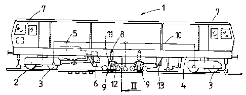
Fig. 1 shows a side view of a machine for stabilizing a
track composed of rails and sleepers, comprising

2~79i42
4
stabilizing units which may be set vibrating
horizontally,
Fig. 2 shows an enlarged cross-section through the
machine in accordance with the sectional line II in Fig.
1, and
Fig. 3 shows a schematized plan view of two stabilizing
units.
The machine 1, shown in Fig. 1 and also universally known
as a track stabilizer, for consolidating the ballast bed of a
track 2 comprises a machine frame 4, supported on on-track
undercarriages 3, with which are associated an energy unit 5
with a motive drive 6 and driver's cabs 7. Between the two
on-track undercarriages 3, arranged at either end, and beneath
the machine frame 4 are provided two stabilizing units 9 which
are adjustable in the vertical direction by means of vertical
adjustment drives 8 and are arranged.one following the other
in the longitudinal direction of the machine. A reference
system 10 serves to monitor the lowering of the track.
Associated with each stabilizing unit 9 is a vibration
generator 11 for generating vibrations which are horizontal or
extend parallel to the track plane and in the transverse
direction of the machine. The vibration generators 11 of the
two stabilizing units 9 are joined together by means of a
mechanical coupling I2 in the form of a cardan shaft and may
be set rotating by means of a drive 13~.
As Fig. 2 shows, each vibration generator II is formed
from two eccentric masses 15 rotating at the same speed in
opposite directions around a common axis 14, extending in the
longitudinal direction of the machine and horizontally, so as
to generate horizontal, sinusoidal vibrations which are
directed transversely to the longitudinal direction of the
machine. when one eccentric mass 15 reaches the highest point

219142
of the circular path, the second eccentric mass 15 is located
at the same moment at its lowest point, i.e. displaced by 180°
relative thereto. Each stabilizing unit 9 is supported on
rails 17 of the track 2 by means of flanged rollers 16 (four
altogether). Each two flanged rollers 16 located opposite one
another in the transverse direction of the machine are
connected to a hydraulic spreading drive 18. The two
eccentric masses 15 are mounted in an auxiliary'housing 19
connected to the vertical adjustment drives 8.
Between the two flanged rollers 16 of each stabilizing
unit 9 respectively associated with one rail 17, a roller
gripper 20 is mounted on the auxiliary housing 19 for pivoting
around an axis 21 extending in the longitudinal direction of
the machine. This pivoting movement is produced by means of a
hydraulic drive 22. At the lower end of each roller gripper
20 is a roller disc 24 which is rotatable around an axis 23.
In order to transmit the vibratory movements to the track 2,
the flanged rollers 16 should be pressed against the
particular rail 17 associated therewith with the aid of the
spreading drive 18. With the operation of the drives 22, the
roller discs 24 are pressed against the exterior sides of the
rail head.
It is clearly visible from the schematic representation
shown in Fig. 3 that the phase difference of the vibrations
generated by the two stabilizing units 9, arranged one
following the other in the longitudinal direction of the
machine, and extending in the horizontal plane and
perpendicularly to the longitudinal direction of the machine
is 180°. Thus one stabilizing unit 9, or its eccentric masses
15, vibrates to the right-hand machine side, for example,
while the other stabilizing unit 9 vibrates at the same time
to the opposite, left-hand machine side. The vibrations are
indicated by arrows 25. The vertical load produced with the
aid of the vertical adjustment drives during the stabilizing
procedure is maintained unchanged in the way known hitherto.

Dessin représentatif
Une figure unique qui représente un dessin illustrant l'invention.
États administratifs

2024-08-01 : Dans le cadre de la transition vers les Brevets de nouvelle génération (BNG), la base de données sur les brevets canadiens (BDBC) contient désormais un Historique d'événement plus détaillé, qui reproduit le Journal des événements de notre nouvelle solution interne.

Veuillez noter que les événements débutant par « Inactive : » se réfèrent à des événements qui ne sont plus utilisés dans notre nouvelle solution interne.

Pour une meilleure compréhension de l'état de la demande ou brevet qui figure sur cette page, la rubrique Mise en garde , et les descriptions de Brevet , Historique d'événement , Taxes périodiques et Historique des paiements devraient être consultées.

Historique d'événement

Description Date
Le délai pour l'annulation est expiré 2015-06-15
Lettre envoyée 2014-06-16
Inactive : CIB de MCD 2006-03-12
Accordé par délivrance 2005-08-02
Inactive : Page couverture publiée 2005-08-01
Inactive : Taxe finale reçue 2005-05-18
Préoctroi 2005-05-18
Un avis d'acceptation est envoyé 2005-04-28
Lettre envoyée 2005-04-28
Inactive : Approuvée aux fins d'acceptation (AFA) 2005-04-05
Modification reçue - modification volontaire 2004-11-29
Inactive : Dem. de l'examinateur par.30(2) Règles 2004-07-13
Inactive : Renseign. sur l'état - Complets dès date d'ent. journ. 2002-05-02
Lettre envoyée 2002-05-02
Inactive : Dem. traitée sur TS dès date d'ent. journal 2002-05-02
Exigences pour une requête d'examen - jugée conforme 2002-04-10
Toutes les exigences pour l'examen - jugée conforme 2002-04-10
Demande publiée (accessible au public) 1996-12-17

Historique d'abandonnement

Il n'y a pas d'historique d'abandonnement

Taxes périodiques

Le dernier paiement a été reçu le 2005-04-15

Avis : Si le paiement en totalité n'a pas été reçu au plus tard à la date indiquée, une taxe supplémentaire peut être imposée, soit une des taxes suivantes :

  • taxe de rétablissement ;
  • taxe pour paiement en souffrance ; ou
  • taxe additionnelle pour le renversement d'une péremption réputée.

Les taxes sur les brevets sont ajustées au 1er janvier de chaque année. Les montants ci-dessus sont les montants actuels s'ils sont reçus au plus tard le 31 décembre de l'année en cours.
Veuillez vous référer à la page web des taxes sur les brevets de l'OPIC pour voir tous les montants actuels des taxes.

Historique des taxes

Type de taxes Anniversaire Échéance Date payée
TM (demande, 2e anniv.) - générale 02 1998-06-15 1998-05-20
TM (demande, 3e anniv.) - générale 03 1999-06-14 1999-05-31
TM (demande, 4e anniv.) - générale 04 2000-06-14 2000-05-25
TM (demande, 5e anniv.) - générale 05 2001-06-14 2001-05-24
Requête d'examen - générale 2002-04-10
TM (demande, 6e anniv.) - générale 06 2002-06-14 2002-05-27
TM (demande, 7e anniv.) - générale 07 2003-06-16 2003-04-07
TM (demande, 8e anniv.) - générale 08 2004-06-14 2004-04-15
TM (demande, 9e anniv.) - générale 09 2005-06-14 2005-04-15
Taxe finale - générale 2005-05-18
TM (brevet, 10e anniv.) - générale 2006-06-14 2006-04-28
TM (brevet, 11e anniv.) - générale 2007-06-14 2007-04-24
TM (brevet, 12e anniv.) - générale 2008-06-16 2008-04-24
TM (brevet, 13e anniv.) - générale 2009-06-15 2009-04-24
TM (brevet, 14e anniv.) - générale 2010-06-14 2010-04-28
TM (brevet, 15e anniv.) - générale 2011-06-14 2011-04-26
TM (brevet, 16e anniv.) - générale 2012-06-14 2012-04-27
TM (brevet, 17e anniv.) - générale 2013-06-14 2013-04-26
Titulaires au dossier

Les titulaires actuels et antérieures au dossier sont affichés en ordre alphabétique.

Titulaires actuels au dossier
FRANZ PLASSER BAHNBAUMASCHINEN-INDUSTRIEGESELLSCHAFT M.B.H.
Titulaires antérieures au dossier
BERNHARD LICHTBERGER
JOSEF THEURER
Les propriétaires antérieurs qui ne figurent pas dans la liste des « Propriétaires au dossier » apparaîtront dans d'autres documents au dossier.
Documents

Pour visionner les fichiers sélectionnés, entrer le code reCAPTCHA :


Pour visualiser une image, cliquer sur un lien dans la colonne description du document. Pour télécharger l'image (les images), cliquer l'une ou plusieurs cases à cocher dans la première colonne et ensuite cliquer sur le bouton "Télécharger sélection en format PDF (archive Zip)" ou le bouton "Télécharger sélection (en un fichier PDF fusionné)".

Liste des documents de brevet publiés et non publiés sur la BDBC .

Si vous avez des difficultés à accéder au contenu, veuillez communiquer avec le Centre de services à la clientèle au 1-866-997-1936, ou envoyer un courriel au Centre de service à la clientèle de l'OPIC.


Description du
Document 
Date
(aaaa-mm-jj) 
Nombre de pages   Taille de l'image (Ko) 
Dessin représentatif 1999-08-10 1 13
Abrégé 1996-06-13 1 20
Description 1996-06-13 5 222
Dessins 1996-06-13 1 23
Revendications 1996-06-13 1 34
Abrégé 2004-11-28 1 17
Description 2004-11-28 6 238
Revendications 2004-11-28 1 32
Dessin représentatif 2005-03-21 1 8
Description 2005-07-31 6 238
Dessins 2005-07-31 1 23
Rappel de taxe de maintien due 1998-02-16 1 111
Accusé de réception de la requête d'examen 2002-05-01 1 179
Avis du commissaire - Demande jugée acceptable 2005-04-27 1 162
Avis concernant la taxe de maintien 2014-07-27 1 172
Taxes 2003-04-06 1 35
Taxes 2002-05-26 1 37
Taxes 2001-05-23 1 36
Taxes 2004-04-14 1 36
Taxes 2005-04-14 1 38
Correspondance 2005-05-17 1 35