Sélection de la langue

Search

Sommaire du brevet 2179329 

Énoncé de désistement de responsabilité concernant l'information provenant de tiers

Une partie des informations de ce site Web a été fournie par des sources externes. Le gouvernement du Canada n'assume aucune responsabilité concernant la précision, l'actualité ou la fiabilité des informations fournies par les sources externes. Les utilisateurs qui désirent employer cette information devraient consulter directement la source des informations. Le contenu fourni par les sources externes n'est pas assujetti aux exigences sur les langues officielles, la protection des renseignements personnels et l'accessibilité.

Disponibilité de l'Abrégé et des Revendications

L'apparition de différences dans le texte et l'image des Revendications et de l'Abrégé dépend du moment auquel le document est publié. Les textes des Revendications et de l'Abrégé sont affichés :

  • lorsque la demande peut être examinée par le public;
  • lorsque le brevet est émis (délivrance).
(12) Demande de brevet: (11) CA 2179329
(54) Titre français: MANCHE ANGULAIRE ET COURBE DE BATON DE HOCKEY
(54) Titre anglais: ANGLED HOCKEY STICK HANDLE WITH CURVE
Statut: Réputée abandonnée et au-delà du délai pour le rétablissement - en attente de la réponse à l’avis de communication rejetée
Données bibliographiques
Abrégés

Abrégé français

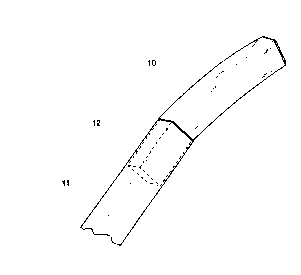
Poignée inclinée pour bâton de hockey conçue pour s'adapter à tout manche de bâton de hockey creux pour fournir une poignée inclinée à un angle de 155 à 175 degrés environ entre la poignée et la longue section droite du manche du bâton de hockey. La poignée comporte une portion plus petite à une extrémité qui rend possible son insertion dans le bout du manche creux du bâton de hockey. La poignée est fixée à l'extrémité du manche au moyen d'un ajustement serré et à l'aide d'un adhésif approprié.


Abrégé anglais


An angled hockey stick grip adapted to fit into any standard hollow hockey stick shaft to
provide an angled grip of approximately 155 to 175 degrees between the grip and the
long straight section of the hockey stick shaft. The handle has a reduced portion at one
end that allows it to be inserted into the end of the hollow hockey stick shaft. The grip is
secured to the end of the shaft by a close fit along with a suitable adhesive.

Revendications

Note : Les revendications sont présentées dans la langue officielle dans laquelle elles ont été soumises.


The embodiments of the invention in which an exclusive property or privilege is
claimed as follows:
1. A curved hockey stick handle that is inserted into the end of any standard hollow
hockey stick shaft that improves the ergonomics of the stick, providing greater control of
the said stick with increased comfort, handling, and mechanical advantage in the use
thereof, said handle comprising:
A straight shaft portion that has a nominal cross section similar to that of a standard
hollow hockey stick shaft that is connected to a curved middle position of same nominal
cross section joining a straight lower portion with a reduced cross section,
insertion means of the lower portion is of the correct cross sectional dimension to allow
it to be inserted into the end of a standard hollow hockey stick shaft using an appropriate
adhesive to help bind the lower portion to the shaft of the hollow hockey stick;
The upper gripping portion of the said handle provides an angled grip relative to the
lower portion with an angle between them of 155 to 175 degrees.

Description

Note : Les descriptions sont présentées dans la langue officielle dans laquelle elles ont été soumises.


2179329
This invention relates generally to hockey sticks and in more particular to the upper
gripping portion at the end of a hollow hockey stick shaft.
Currently there are many di~ele-~t designs of hockey sticks that can be found on the
market. In general they can be broken down into two basic classes 1) The traditional style
of stick, which is a solid one piece construction and mostly made from wood or 2) A
more recent design which uses a three piece cons~tion involving a durable shai~ which
is generally hollow at opposite ends that allow for the addition of a replaceable blade and
a wooden end handle. It is this second style of stick that this invention relates most
closely to. The shaft of this class of sticks has been made from many materials such as
alllminum or graphile composites and has been increasing in popularity since their
introduction because of possible increased performance andlor value compared to the
traditional one piece sticks.
An advantage to the three piece design is that the player will likely only break the blade
of the hockey stick because the shaft is extremely durable. Thus the player will keep a
shaft for a long period of time and only have to replace the blade. At the other end of the
shaft opposite the blade part, there is a wooden handle that is inserted into the end to
finish offthe hollow shaft. In general this wooden handle is designed to be inserted into
the shaft similarly to the blade portion, using a close fit and ayl)ro~liate adhesive. The
wooden handle is shaped similarly to the shaft such that the transition from the hollow

2179329
-
shaft to the wooden handle is almost unnoticeable to the touch of the hand and continues
to form a straight shaft.
The problems noted with a straight shaft configuration can be analyzed from two basic
perspectives.
The first problem is the stress that is applied to the wrist when gripping a straight shaft
when engaged in the game of hockey. During the course of play it is noted that many
times a player will have to bend at the wrist to m~int~in a proper grip on the stick. Even
in a fairly common natural grip position during pl~y, the wrist would have to be bent
while keeping the blade on the ice. This is not comfortable for the player and possibly
limits the amount of movement the player has with the stick. It is well known among
players of the game that increased mobility and responsiveness of the stick is desirable
when handling and propelling the puck.
The second problem with a straight shaft is that it limits the mechanical advantage that a
player can have when applying torque to the stick . To propel a hockey puck a player
often desires to apply torque to the shaft ofthe stick in conjull~lion with a swinging
motion. The torque is tr~ncl~ted to the blade of the stick which eventually contacts the
puck. The manner of this action is sometimes a quick "sl~apl)ing" of the wrist or in other
cases a more gradual exertion. In a straight shaft configuration the mechanical advantage

- 2179~9
the player receives is the lever arm about the cross sectional center of the shaft, which is
a relatively limited advantage as the cross section of the stick is small.
There have been attempts to improve these problems with the development of an angled
handle accessories for attac~nent to the end of the hockey stick shaft. ~US Patent
4,S53,753). None of these designs have proliferated into common use among hockey
players. These accessories are a~ward and do not provide a good solution to
the problems created by a straight shaft.
The angle between the shaft and the handle that these inventions provide is significantly
too large to provide a hockey stick with the optimum performance. A large change in
angle between shaft and handle - such as used in other inventions - takes away from the
natural feel of the stick to such a degree that it can feel awkward in the hands of a player
accustomed to a straight shaft.
Another problem with these inventions is that they use a downward opening socket that
the end of the hockey shaft is inserted into. This socket increases the cross-sectional area
of the sticks shaft at the point of connection to create a sort of lump. This lump is
undesirable to players that prefer a constant smooth transition between the shaft and the
end handle.

~ 21793Z9
And finally the last problem with these inventions is that the transition between the
angled handle and the sha~ is very sharp. This meaning that there is no curve to help
soften the transition between the shaft and the handle. This is not conductive to giving
the stick a more natural feel because the end handle has a very distinct or abrupt start
making the stick feel less flowing or continuous in the hands of the player.
The object of this invention is to provide a handle for hollow hockey stick shafts which
provides a better ergonomic configuration that is more comfortable and also increases the
p~lr~ ance of the stick when en~ed in the game of hockey.
Another object of the invention is to provide an angled handle which allows a more
homogenous or natural feel to the stick because the handle is integrated into the shaft.
Thus having a less noticeable transition area between the shaft and handle, by the touch
of the hand.
Another object is to provide a mechanical advantage to the player to improve the ability
of the player to propel the puck at higher speeds and allow for a faster stick motion that is
used to snap the puck upward in a very vertical shot.
It is another object that the handle provide a grip which is less likely to be awkward to
those players that are f~ r to using a straight sha~/handle hockey stick.

- 2i73329
A further object is to provide an angled handle for a hockey stick that can be inserted into
any standard hollow hockey stick shaft. Without increasing the difficulty or expense of
m~nllfacturing the shaft itself.
In the case of hollow hockey stick shafts these disadvantages may be overcome by
providing an angled end grip that is inserted into the end of any hollow hockey stick
shaft. The angle in the range of 155 to 175 degrees between the handle and the long
section of the shaft decreases the strain on the ~vrist and creates a better lever arm to
torque the stick when propelling the puck. The result is an impraved grip that increases
the performance of the stick when playing hockey.
The angle is created by a gradual bend in the handle to form a curved transition between
the angled handle and the long straight section of the shaft this allows for a continuous
feel to the stick. The grip also has a reduced section that allows it to fit snugly into the
end of the shaft while preventing any change in thickness to the shaft at the point of
connection. These important design considerations make the stick more similar to the
straight shaft stick thus making the stick less awkward to those ~mili~r with using the
straight shaft stick.
The technology that is used to secure the straight shaft handle, which is a snug fit and a
therma-type adhesive (Common name: Hot &lue), is utili~ed in the instance of this
invention. This allows any player with a hollow hockey stick shaft to replace the straight

- 2179329
.
handle of the current design with this invention. As well any new shaft sold could have
this invention inserted into the end with possibly no change to the design of the hollow
stick shaft.
The angled grip could be constructed from a durable plastic or wood. When selecting a
material there are advantages and disadvantages to each. Wood is the most a~)~3 ~l iate
material to use because ofthe typical players ~mili~rity with it's weight and stiffness in
the case of hockey sticks.
The invention is explained below with reference to an illustrative embodiment
represented in the drawings:
Fig. 1 A perspective view of a grip inserted into the end of the hollow hockey stick shaft.
Fig. 2 A side elevation view of the device;
Fig. 3 A left hand back view of the device of Fig. 2, looking in the direction indicated by
arrow A;
Fig. 4 A right hand view of the front of the device of Fig. 2, looking in the direction
indicated by arrow B;
Fig. S A side view showing a hollow hockey stick with the handle inserted.
Turning now to a more detailed consideration of the present invention, there is illustrated
in Fig. 1 an angled hockey stick grip or handle. The shape of the handle 10 provides for a

217~32~
smooth transition between the handle and the shaft 11. The handle has a reduced area 12
that allows it to fit inside the end of the hollow shaft 11. The area of the handle at 12 is
coated with a applol) iate thermo-adhesive. This adhesive becomes liquid when heated to
allow the handle 10 to be removed and inserted from the shaft 11.
The handle 10 is constructed from an a~-ol,-iate stiffand light material such as plastic
or wood. Wood construction has benefits because of its more common use in hockey and
thus players have more f~ rity with it's feel. Wood construction could involve
shaping or bending solid wood or l~ ;ng thin strips of wood together with the
ap~)rol)-iate glue.
Referring to Fig. 2 the upper portion of the handle 13 provides an angle between the
lower portion 14 in the range of 155 to 175 degrees (Reference Dimension C). This
creates an angle that is comfortable when holding the stick and as well gives a
mechanical advantage to the player when propelling the puck.
The bottom end of the handle 14 is given a chamfer 15 to help guide the end of the
handle into the end of the shaft making it easier to change the handle. The bottorn portion
14 is coated with an applop-iate adhesive that allows the handle to be removed and
inserted, such an adhesive could be hot glue.

2179~29
-
The length of the handle (Reference Dimenslon L) is approximately 4 to 6 inches to
provide an adequate length for the hand to grip. The handle has a soft curved section 17
to provide a gradual transition from the upper portion 13 to the lower portion 14.
The width and height of the handle (Reference Dimension W and ~ respectively) would
be the same as the standard dirnensions for the hockey stick shafts on the marke~ today
and any future changes that may occur. These are approximately 25/32 inches by 1 1/32
inches although this varies slightly among the various manufactures.

Dessin représentatif
Une figure unique qui représente un dessin illustrant l'invention.
États administratifs

2024-08-01 : Dans le cadre de la transition vers les Brevets de nouvelle génération (BNG), la base de données sur les brevets canadiens (BDBC) contient désormais un Historique d'événement plus détaillé, qui reproduit le Journal des événements de notre nouvelle solution interne.

Veuillez noter que les événements débutant par « Inactive : » se réfèrent à des événements qui ne sont plus utilisés dans notre nouvelle solution interne.

Pour une meilleure compréhension de l'état de la demande ou brevet qui figure sur cette page, la rubrique Mise en garde , et les descriptions de Brevet , Historique d'événement , Taxes périodiques et Historique des paiements devraient être consultées.

Historique d'événement

Description Date
Inactive : CIB désactivée 2015-03-14
Inactive : CIB du SCB 2015-01-17
Inactive : Symbole CIB 1re pos de SCB 2015-01-17
Inactive : CIB expirée 2015-01-01
Demande non rétablie avant l'échéance 1999-06-18
Le délai pour l'annulation est expiré 1999-06-18
Réputée abandonnée - omission de répondre à un avis sur les taxes pour le maintien en état 1998-06-18
Demande publiée (accessible au public) 1997-12-19

Historique d'abandonnement

Date d'abandonnement Raison Date de rétablissement
1998-06-18
Titulaires au dossier

Les titulaires actuels et antérieures au dossier sont affichés en ordre alphabétique.

Titulaires actuels au dossier
MARK FLETCHER
BRUCE FLETCHER
Titulaires antérieures au dossier
S.O.
Les propriétaires antérieurs qui ne figurent pas dans la liste des « Propriétaires au dossier » apparaîtront dans d'autres documents au dossier.
Documents

Pour visionner les fichiers sélectionnés, entrer le code reCAPTCHA :


Pour visualiser une image, cliquer sur un lien dans la colonne description du document. Pour télécharger l'image (les images), cliquer l'une ou plusieurs cases à cocher dans la première colonne et ensuite cliquer sur le bouton "Télécharger sélection en format PDF (archive Zip)" ou le bouton "Télécharger sélection (en un fichier PDF fusionné)".

Liste des documents de brevet publiés et non publiés sur la BDBC .

Si vous avez des difficultés à accéder au contenu, veuillez communiquer avec le Centre de services à la clientèle au 1-866-997-1936, ou envoyer un courriel au Centre de service à la clientèle de l'OPIC.


Description du
Document 
Date
(aaaa-mm-jj) 
Nombre de pages   Taille de l'image (Ko) 
Description 1996-09-26 8 265
Abrégé 1996-09-26 1 13
Revendications 1996-09-26 1 27
Dessins 1996-09-26 1 16
Dessin représentatif 1998-01-21 1 4
Avis de rappel: Taxes de maintien 1998-03-18 1 120
Courtoisie - Lettre d'abandon (taxe de maintien en état) 1998-07-15 1 189
Avis de rappel: Taxes de maintien 1999-03-21 1 119