Sélection de la langue

Search

Sommaire du brevet 2179366 

Énoncé de désistement de responsabilité concernant l'information provenant de tiers

Une partie des informations de ce site Web a été fournie par des sources externes. Le gouvernement du Canada n'assume aucune responsabilité concernant la précision, l'actualité ou la fiabilité des informations fournies par les sources externes. Les utilisateurs qui désirent employer cette information devraient consulter directement la source des informations. Le contenu fourni par les sources externes n'est pas assujetti aux exigences sur les langues officielles, la protection des renseignements personnels et l'accessibilité.

Disponibilité de l'Abrégé et des Revendications

L'apparition de différences dans le texte et l'image des Revendications et de l'Abrégé dépend du moment auquel le document est publié. Les textes des Revendications et de l'Abrégé sont affichés :

  • lorsque la demande peut être examinée par le public;
  • lorsque le brevet est émis (délivrance).
(12) Brevet: (11) CA 2179366
(54) Titre français: SOUPAPE DE DECHARGE MONOPIECE DESTINEE AUX SYSTEMES DE REFROIDISSEMENT DE TRANSMISSION
(54) Titre anglais: ONE-PIECE PRESSURE RELIEF VALVE FOR TRANSMISSION COOLING SYSTEM
Statut: Durée expirée - au-delà du délai suivant l'octroi
Données bibliographiques
(51) Classification internationale des brevets (CIB):
  • F16H 57/04 (2010.01)
  • F16K 17/04 (2006.01)
(72) Inventeurs :
  • GILROY, ALAN S. (Etats-Unis d'Amérique)
  • GAIDA, DENNIS C. (Etats-Unis d'Amérique)
(73) Titulaires :
  • FORM RITE
(71) Demandeurs :
  • FORM RITE (Etats-Unis d'Amérique)
(74) Agent: GOWLING WLG (CANADA) LLP
(74) Co-agent:
(45) Délivré: 2000-03-21
(22) Date de dépôt: 1996-06-18
(41) Mise à la disponibilité du public: 1997-02-08
Requête d'examen: 1997-05-22
Licence disponible: S.O.
Cédé au domaine public: S.O.
(25) Langue des documents déposés: Anglais

Traité de coopération en matière de brevets (PCT): Non

(30) Données de priorité de la demande:
Numéro de la demande Pays / territoire Date
08/511,744 (Etats-Unis d'Amérique) 1995-08-07

Abrégés

Abrégé français

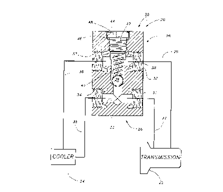
Une soupape de décharge monopièce est incorporée dans un système de refroidissement d'une transmission. La soupape de décharge monopièce remplace le système de l'état de la technique précédent qui utilise plusieurs connexions en T pour obtenir les fonctions de la soupape de décharge. La soupape de décharge monopièce réduit le nombre de connexions fluides sur le système de refroidissement de la transmission, ce qui réduit la possibilité de fuite.


Abrégé anglais

A one-piece relief valve is incorporated into a transmission cooling system. The one-piece relief valve replaces the prior art system which have usedplural T-connections to achieve the relief valve fun ction. The one-piece relief valve reduces the number of fluid connections on the transmission cooling system, thus reducing the possibility of leakage.

Revendications

Note : Les revendications sont présentées dans la langue officielle dans laquelle elles ont été soumises.


We claim:
1. A transmission fluid cooling system comprising:
a transmission;
a cooling unit;
a supply line leading from said transmission to said cooling unit;
a return fluid line leading from said cooling unit back to said transmission;
and
a one-piece relief valve body mounted between said transmission and said
cooling unit,
and receiving an inlet flow from said supply line, and also receiving fluid
from said return
fluid line such that fluid leaving said transmission passes through a first
bore in said valve
body and to said cooling unit, and fluid leaving from said cooling unit back
to said
transmission passes through a second bore in said valve body, and a relief
bore connecting sai d
first and second bores in said valve body, said relief bore receiving a relief
valve such that if
the fluid pressure on said first bore exceeds a predetermined relief pressure
on said relief, said
relief valve unseats and allows fluid to move from said first bore directly
into said second
bore.
2. A transmission cooling system as recited in claim 1, wherein said first and
second
bores are parallel.
3. A transmission cooling system as recited in claim 2, wherein said relief
bore is
perpendicular to said first and second bores.
6

4. A transmission cooling system as recited in claim 1, wherein said relief
bore is
formed from an outer face of said valve body, said relief bore receiving a
plug to close said
relief bore at an outer end on said outer face, and said plug being adjacent
to said second bore.
5. A transmission cooling system as recited in claim 4, wherein an O-ring seal
surrounds said plug to seal said relief valve.
6. A transmission cooling system comprising:
a transmission receiving a hydraulic fluid;
a cooling unit for cooling said hydraulic fluid from said transmission;
a hydraulic fluid supply line leading from said transmission to said cooling
unit and a
hydraulic fluid return line leading from said cooling unit to said
transmission; and
a one-piece relief valve body disposed between said transmission and said
cooling unit,
said supply line and said return line both passing through said one-piece
valve body, said
one-piece valve body having first and second parallel bores, with said first
bore forming a portion
of said supply line and said second bore forming a portion of said return
line, and a relief bor a
interconnecting said first and second bores, said relief bore being
perpendicular to said first
and second bores, said relief bore including a spring biased valve, such that
if pressure in said
first bore exceeds a force on said valve said valve unseats and allows said
hydraulic fluid to
move from said first bore into said second bore, and thus back into said
return line to said
transmission.
7

7. A transmission system as recited in claim 6, wherein said relief bore
includes a plug
received in a hole cut into an outer face of said one-piece valve body to from
said relief bore,
said outer face being adjacent said second bore.
8. A method for bypassing a cooling system in a transmission fluid system
comprising
the steps of:
a) forming a supply port in a first rigid body and a return port in a second
rigid body;
b) forming a fluid passage between said supply port and said return port in a
third
rigid body;
c) forming a relief valve between said supply port and said return port, said
relief
valve opening under sufficient pressure differential between said supply port
and said return
port;
d) said first, second, and third rigid bodies of steps a. and b. being formed
as a
one-piece item; and
e) then connecting said supply port to a first fluid line connecting a
transmission case
to a transmission fluid cooler and connecting said return port to a second
fluid line connecting
said transmission case to said transmission fluid cooler.
9. The method of claim 8 wherein said step (a) further comprises the steps of:
said first, second, and third rigid bodies forming a single valve body;
forming a supply
bore through said supply port in said single valve body; and
forming a return bore through said return port in said single valve body.
8

10. The method of claim 9 wherein step (b) further comprises the step of
forming a
relief bore through said single valve body connecting said supply bore and
said return bore.
11. The method of claim 10 further comprising the steps of:
forming said relief valve in said relief bore; opening said relief valve in
said relief bore
when the pressure difference between said supply bore and said return bore
exceeds a
predetermined amount, thereby allowing fluid to flow between said supply bore
and said return
bore.
12. A transmission fluid cooling system comprising:
a transmission; a cooling unit;
a one-piece relief valve unit mounted between said transmission and said
cooling unit,
said one-piece relief valve unit including a first port in fluid communication
with a supply fluid
line and a second port in fluid communication with a return fluid line;
said one-piece relief valve unit including a relief valve disposed in a bypass
line
between said first port and said second port, said relief valve permitting
flow through said
one-piece relief valve unit from said first port to said second port when the
pressure difference
between said first port and said second port exceeds a predetermined value;
and
sais first port, said second port, and said bypass line being formed in an
integral
housing member.
13. The transmission fluid cooling system of claim 12, wherein said integral
housing
member is a single piece of material.
9

Description

Note : Les descriptions sont présentées dans la langue officielle dans laquelle elles ont été soumises.


` ~ 21 79366
ONE-PIECE PKESSURE KELIEF VALVE FOK
TRANSMISSION COOLING SYSTEM
BACKGROUND OF THE INVENTION
S This invention relates to a pressure relief valve for the eooling system of a vehicle tr~nsmisci-m
In the prior art vehieles are typieally equipped with tr:lncmiscionc that
provide different speed ratios between the engine and the drive axles. A
tr~ncmiscinn typieally generates a good deal of heat, and thus oil is eireulated to eool the tr~nsmicsion ~ ul~ L~.
The oil in the tr:lncmiccion beeomes quite hot during operation of the
vehiele. Thus, the oil is typieally routed to a eooling unit. The eooling unit
eools the oil whieh is then returned to the trAncmiccir~n
The tr~ncmiccion is spaeed some distance from the cooling unit. As sueh,
fluid lines, sueh as eonduits or hoses must travel the distanee from the
trr~ncmiccion to the eooling unit. The oil travels between the tr~ncmiccif n andeooling unit through the fluid lines.
When the vehiele is eool, the oil is relatively viseous and does not move
quiekly. When the engine is running, oil is ~ ontinllollcly being moved to the
eooling unit, and from the eooling unit baek to the tr~ncmiccion The oil does
not move quiekly through the eooling unit. There is often a baek pressure on
the line leading to the eooling unit. For this reason, some tr~ncmicci-m eoolingunits have ineorporated a relief valve for returning a portion of the tr~ncmiccil-n
fluid from the line leading to the eooling unit direetly baek into the line leading
baek to the transmission. In the past, these relief valves have ineluded separate
eomponents sueh as a pair of T-eonneetions. The separate :u~ e~ result

`` ~ 2179366
in an unduly high amount of fluid c<!nnrctir)nc~ and also additional parts which
require additional assembly time.
The more fluid (nnn~cti-~nc that are created in a tr~ncmicci-n cooling
system, the more places there are that could potentially leak. A ~ ;.,ll oil
5 leak could be very damaging to the vehicle, and could lead to seizure of the
tr~3ncmiccinn. Thus, the relatively high number of fluid cf~nn~tinnC is
undesirable.
SUMMARY OF THE INVENTION
The disclosed embodiment of this invention includes a one-piece pressure
10 relief valve body incorporated between a tr~ncmiCci- n and a cooling unit for the
trnncmiccinn. A fluid line leads to the valve body, and the valve body includes
a bore connected to another fluid line leading to the cooling unit. From the
cooling unit another line leads back to the valve body, and a second bore is
connected to a fluid line which leads back to the tr~ncmicci(m The two bores
15 described above extend generally parallel to each other. A pressure relief bore
extends perpendicular to the two bores, and connects the two bores. A spring
biased relief valve is mounted in the relief bore.
When the fluid pressure in the line leading from the tr~ncmiccif)n
overcomes the spring bias on this ball valve, the oil is allowed to flow through
20 the relief bore directly back to the tr~ncmicci- n Since the one-piece valve body
contains all of the fluid ~onn~cfifmc there are a smaller number of fluid
cCmn~ti~-nC, and also a smaller number of required parts than in the prior art
This reduction in the number of fluid connections and required parts is
-2-

21 79366
partieularly important in a tr~nsmic~i-m. It is most undesirable to have the
tr~ncmission oil leaking.
In other features of this invention, the relief bore is formed in the one-
pieee valve body by eutting an aperture from an outer end of the body at a side
S of the body adjacent the return line to the trAncmiCci--n A plug seals the
aperture. Sinee the plug is adjaeent the return line, it is subject to lower
pressure fluid than if it were formed adjacent the line leading from the
trznsmiscion to the cooling unit. The plug is preferably formed with an O-ring
to complete the seal.
These and other features of the present invention can be best understood
from the following specification and drawings, of which the following is a brief
deseription.
BRIEF DESCRIPTION OF THE DRAVVINGS
Figure 1 is a sehematie view showing a tr~ncmi~sion and eooling unit with
15 a relief valve mounted at an inf~rm~ t~ loeation.
DETAILED DESCRIPTION OF A PREFERRED EMBODIMENT
A transmission eooling system 20 ineorporates a trAn~mi~ n 22 and a
eooling unit 24, both shown 5~ h~nn~ti/ ~11y. A supply fluid line 26 ineludes fluid
line 27 which leads from the tr~n~misci-~n toward the eooling unit. A return
20 fluid line 28 ineludes a fluid line 29 that returns oil from the eooling unit to the
tr~nsmic~ n A known circulating system, such as a pump, is utilized to move
the tr~ncmi~ n fluid through line 26 to the cooling unit, and then to return oil
through line 28.
-3 -

~ 21 7q366
A one-piece relief valve 32 is incorporated into the system 20 between
the tr~ncmiccinn 22 and the cooling unit 24. A first fluid port 31 receives fluid
line 27 and another port 32 receives line 29. A bore 33 connects port 31 to a
port 34. Port 34 is connected to a fluid line 35 leading to the cooling unit 24.A fluid line 36 leads from the cooling unit 24 to a port 37. A bore 38 connects
port 37 to port 32, and thus back to the fluid line 29. During normal operation,hydraulic fluid moves through supply line 26 from the transmission 22, into line27, through bore 33, into line 35, and to the cooling unit 24. The fluid is cooled
and returned through fluid line 28, including line 36, bore 38, port 32, and line
29.
When the vehicle is cold, the trAncmiccinn fluid does not move as rapidly
as it does when the vehicle is warm. As such, under cold operation a large back
pressure may develop in the fluid line 26. That pressure also exists in bore 33.
A relief valve 39 is mounted against a valve seat 40. The re~ief valve
moves within a relief bore 41, and is biased by a spring 42 against seat 40.
Should the pressure in bore 33 overcome the force of the spring, the relief valve
3g unseats, and the tr~ncmiccion oil may move directly from line 26 back into
line 28. In the inventive relief valve, the bores 33 and 38 extend parallel to each
other, and the relief bore 41 and valve seat 40 both extend perpendicular to thebores 33 and 38.
Moreover, the relief bore 40 is preferably formed by drilling a hole in the
valve body from an end adjacent to the return lirle. A plug 44 is mounted to fill
the hole. Arl O-ring 46 seals the plug at the hole 48 which is formed through
-4--

21 79366
the end of the one-piece valve body. Since the hole 48 is formed on the return
side, the seal 46 will be exposed to lower pressure fluid than if it were formed
on the side adjacent to bore 33.
The inventive one-piece relief valve greatly reduces the number of fluid
5 ~ onn~ ti--n~ for the trAncmiccion cooling system, thus ~ olldil~ reducing
the number of parts and connections that potentially leak.
A preferred embodiment of the invention has been disclosed, however,
a worker of ordinary skill in the art would recognize that certain modifications
would come within the scope of this invention. For that reason the following
10 claims should be studied to determine the true scope and content of this
invention.

Dessin représentatif
Une figure unique qui représente un dessin illustrant l'invention.
États administratifs

2024-08-01 : Dans le cadre de la transition vers les Brevets de nouvelle génération (BNG), la base de données sur les brevets canadiens (BDBC) contient désormais un Historique d'événement plus détaillé, qui reproduit le Journal des événements de notre nouvelle solution interne.

Veuillez noter que les événements débutant par « Inactive : » se réfèrent à des événements qui ne sont plus utilisés dans notre nouvelle solution interne.

Pour une meilleure compréhension de l'état de la demande ou brevet qui figure sur cette page, la rubrique Mise en garde , et les descriptions de Brevet , Historique d'événement , Taxes périodiques et Historique des paiements devraient être consultées.

Historique d'événement

Description Date
Inactive : Périmé (brevet - nouvelle loi) 2016-06-18
Inactive : CIB désactivée 2011-07-29
Inactive : CIB attribuée 2010-03-11
Inactive : CIB en 1re position 2010-03-11
Inactive : CIB expirée 2010-01-01
Inactive : CIB de MCD 2006-03-12
Inactive : TME en retard traitée 2005-07-22
Lettre envoyée 2005-06-20
Accordé par délivrance 2000-03-21
Inactive : Page couverture publiée 2000-03-20
Préoctroi 1999-12-15
Inactive : Taxe finale reçue 1999-12-15
Un avis d'acceptation est envoyé 1999-10-20
Lettre envoyée 1999-10-20
Un avis d'acceptation est envoyé 1999-10-20
Inactive : Approuvée aux fins d'acceptation (AFA) 1999-09-29
Inactive : Acc. réc. RE - Pas de dem. doc. d'antériorité 1997-09-18
Inactive : Dem. traitée sur TS dès date d'ent. journal 1997-09-16
Inactive : Renseign. sur l'état - Complets dès date d'ent. journ. 1997-09-16
Toutes les exigences pour l'examen - jugée conforme 1997-05-22
Exigences pour une requête d'examen - jugée conforme 1997-05-22
Demande publiée (accessible au public) 1997-02-08

Historique d'abandonnement

Il n'y a pas d'historique d'abandonnement

Taxes périodiques

Le dernier paiement a été reçu le 1999-04-20

Avis : Si le paiement en totalité n'a pas été reçu au plus tard à la date indiquée, une taxe supplémentaire peut être imposée, soit une des taxes suivantes :

  • taxe de rétablissement ;
  • taxe pour paiement en souffrance ; ou
  • taxe additionnelle pour le renversement d'une péremption réputée.

Les taxes sur les brevets sont ajustées au 1er janvier de chaque année. Les montants ci-dessus sont les montants actuels s'ils sont reçus au plus tard le 31 décembre de l'année en cours.
Veuillez vous référer à la page web des taxes sur les brevets de l'OPIC pour voir tous les montants actuels des taxes.

Titulaires au dossier

Les titulaires actuels et antérieures au dossier sont affichés en ordre alphabétique.

Titulaires actuels au dossier
FORM RITE
Titulaires antérieures au dossier
ALAN S. GILROY
DENNIS C. GAIDA
Les propriétaires antérieurs qui ne figurent pas dans la liste des « Propriétaires au dossier » apparaîtront dans d'autres documents au dossier.
Documents

Pour visionner les fichiers sélectionnés, entrer le code reCAPTCHA :


Pour visualiser une image, cliquer sur un lien dans la colonne description du document. Pour télécharger l'image (les images), cliquer l'une ou plusieurs cases à cocher dans la première colonne et ensuite cliquer sur le bouton "Télécharger sélection en format PDF (archive Zip)" ou le bouton "Télécharger sélection (en un fichier PDF fusionné)".

Liste des documents de brevet publiés et non publiés sur la BDBC .

Si vous avez des difficultés à accéder au contenu, veuillez communiquer avec le Centre de services à la clientèle au 1-866-997-1936, ou envoyer un courriel au Centre de service à la clientèle de l'OPIC.


Description du
Document 
Date
(aaaa-mm-jj) 
Nombre de pages   Taille de l'image (Ko) 
Revendications 1997-11-11 4 128
Abrégé 1996-09-26 1 10
Description 1996-09-26 5 169
Revendications 1996-09-26 4 72
Dessins 1996-09-26 1 25
Dessin représentatif 1998-03-24 1 24
Dessin représentatif 2000-02-01 1 13
Accusé de réception de la requête d'examen 1997-09-17 1 173
Rappel de taxe de maintien due 1998-02-18 1 111
Avis du commissaire - Demande jugée acceptable 1999-10-19 1 164
Avis concernant la taxe de maintien 2005-08-14 1 172
Quittance d'un paiement en retard 2005-08-17 1 165
Correspondance 1999-12-14 1 26
Taxes 1998-04-26 1 32