Note : Les descriptions sont présentées dans la langue officielle dans laquelle elles ont été soumises.
21~1023
HYDRAULIC SERVOVALVE
BACKGROUND OF THE INVENTION
Field of the Invention:
The present invention relates to a hydraulic servovalve,
and more particularly to a hydraulic servovalve havlng a sleeve
and a spool for controlling a direction of flow of a working
fluid and a flow rate of the working fluid, especially water,
between a plurality of ports.
Description of the Related Art:
There have been known hydraulic servovalves which employ
minerdl oil as a working f luid . Since the mineral oil is
combustible, it needs to be handled with special care. When
drained from hydraulic servovalves and simply left unprocessed,
the mineral oll tends to cause envlll l dl pollutlon. For
these reasons, attention has been directed to hydraulic
servovalves which employ water as a working fluid. However,
the water used as a working fluid in hydraulic servovalves also
poses certain problems because it causes relatively large
leakage as its viscosity is lower than the viscosity of the
mineral oil, resulting in poor servovalve ~ff;~ nf~y, and it
develops large friction between sliding parts of the hydraulic
servovalves .
FIG. 10 of the ~r~ , ying drawings shows a hydraulic
servovalve which has been developed to solve the above
problems. As shown in FIG. 10, the hydraulic servovalve
includes a valve body l having a spool hole 2 def ined therein
which houses a spool 13 axially movably therein for rhi:ln~; n!J
-
218~23
directions of a working fluid and also varying a flow rate of
the working fluid. The spool hole 2 has a central annular
groove 3 and a pair of annular grooves 4L, 4R positioned one on
each side of the central annular groove 3. The annular groove
5 3 communicates with a supply port P, and the annular grooves
4L, 4R ~ te wlth return ports Rl, R2, respectively
connected to a tank. The annular grooves 4L, 4R are connected
respectively through pas8ages 7L, 7R to a central chamber 8
defined in the valve body 1.
An annular clearance C is defined between the inner
ci, ~ Lial surface of the spool hole 2 and the outer
circumferential surface of the spool 13 which is axially
movably housed in the spool hole 2. The spool 13 has a pair of
axially spaced smaller-diameter portions 14L, 14R which are
15 slightly shorter axially than the axial distance between the
annular groove 4L and the annular groove 3 and the axial
distance between the annular groove 3 and the annular groove
4R, respectively. The outer circumferential surfaces- of these
smaller-diameter portions 14L, 14R and the inner
20 circumferential surface of the spool hole 2 jointly define
respective chambers 9L, 9R which are held in ~ Ini~tion with
respective control ports Cl, C2.
As shown in FIG. 10, a load ( an actuator ) such as a
cylinder or a motor is connected to the control ports Cl, C2,
25 and the load is actuated and controlled by regulating a flow
rate or a pressure of a working fluid flowing from the supply
port to the control port or f rom the control port to the return
port by adj usting the valve opening . The areas of the control
~8~ 023
orifices A1, A2, B1 and B2 which are defined by displacement of
the spool in the valve body are areas of cylindrical side faces
which are defined by an outer diameter of the spool and a
disrl ~ t of the spool from a neutral position. That is,
5 the working fluid flows out or flows in from fully
circumferentially around the spool.
Springs llL, llR are housed in respective pilot chambers
lOL, lOR that are defined between opposite end faces of the
spool 13 and the inner wall surfaces of the spool hole 2. The
10 pilot chambers lOL, lOR communicate respectively through
passages 12L, 12R with respective nozzle back-pressure chambers
6L, 6R.
Opposite end portions of the spool 13 are supported by
respective llydl~ l dtic bearings 15L, 15R having respective
15 pockets 16L, 16R and respective orifices 17L, 17R and held in
communication with the annular groove 3 through a passage 18.
Therefore, the supply port P ~ Inic~tes with the nozzle back-
plt:4~ule chambers 6L, 6R through the annular groove 3, the
passage 18, the hydrostatic bearings 15L, 15R, the annular
20 clearance C, the pilot chambers lOL, lOR, and the passages 12L,
12R .
The nozzle back-pressure chambers 6L, 6R ~ Ini ~te with
the central chamber 8 through respective nozzles 5L, 5R which
are open toward a flapper 19 disposed in the central chamber 8.
25 ~he flapper 19 can be actuated by a torque motor 20 mounted on
the valve body 1.
Operation of the hydraulic servovalve shown in FIG. 10
will be described below with respect to a right-hand half of
218~23
the servovalve. The working fluid supplied from the pump flows
from the supply port P through the passage 18, the orlfice 17R,
the pocket 16R, the annular clearance C, the pilot chamber lOR,
the passage 12R, the nozzle back-pressure chamber 6R, the
5 nozzle 5R and a clearance between the nozzle 5R and the flapper
19 into the central chamber 8. Then, the working fluid flows
from the central chamber 8 through the passage 7R, the annular
groove 4R, and the return port R2 into the tank.
At this time, a working fluid which flows leftward in FIG.
10 10 from the pocket 16R and returns through the annular groove
4R and the return port R2 into the tank causes a loss. The
flow rate of such a working fluid can be adjusted ~Pr~n~9~n~ on
the ~ n of the annular clearance C, the shape of the
pocket 16R, and other factors.
In FIG. 10, fluid passages are directly formed in the
valve body, however, a 81eeve, which is a separate member from
the valve body, may be fitted in the valve body and is
effective for forming more complicated fluid passages.
The spool 13 is supported by the hydrostatic bearings 15R,
20 15L out of contact with the inner clrcumferential surface of
the spool hole 2. Since there is thus no friction between the
spool 13 and the inner circumferential surface of the spool
hole 2, the hydraulic servovalve is free of frictional wear on
the moving parts and hence structural and performance
25 deterloration which would otherwlse occur due to frictional
wear. Tn~ h as the spool 13 is YU~)~UL l ed out of contact
with the inner circumferential surface of the spool hole 2, it
is not n~ ~y to machine the spool 13 and the spool hole 2
21~1023
with high accuracy.
The control flow rate of a working fluid depends on a
supply pressure of the working fluid and the areas of the
control orifices, and the areas of the control orifices are
5 det~rml nPfl by the outer fll i Lt:- of the spool and a
displacement of the spool in the spool type valve. The
servovalve having a suitable control flow rate should be
selected in accordance with intended use. For example, in
controlling a hydraulic motor at a high torque and a low
10 rotational speed by the servovalve, the servovalve which can
handle a high supply pressure and a small control flow rate of
a working f luid should be selected .
If the hydraulic servovalve is to handle a small control
flow rate of a working fluid, i.e., is to be of a small
15 capacity, then it ls nol~Psqiqrv to reduce the cross-sectional
area of a control orifice defined by the spool 13 and the inner
circumferential surface of the spool hole 2. In this case, it
is conceivable to reduce the fl; q~nnq of the spool 13 and the
spool hole 2. However, since the working fluid flows from
20 fully circumferentially around the spool 13, the ~; e;nnq of
the spool 13 and the 8pool hole 2 have to be rnnq; fl~rably
reduced in oraer to reduce the cross-sectional area of the
control orifice. However, there have been certain limitations
or difficulties in m--~h;n;n~ the spool 13 and the spool hole 2
25 highly accurately for such reduced ~ nnq. If, on the
other hand, the fl~- q1 nnq of the spool 13 and the spool hole
2 are selected for easier m~hini~h; 1 ;ty, then it is necessary
to greatly reduce an axial displacement of the spool 13,
2~g~ ~23
resulting in poor stability of the servovalve.
SUMMARY OF THE INVENTION
It is therefore an object of the present invention to
5 provide a hydraulic servovalve which can handle a small control
flow rate of a working fluid without reducing the dimensions of
a spool and a spool hole which houses the spool, and has an
automatic centering r~rAh;1;ty for automatically centering the
spool in the spool hole.
According to the present invention, there is provided
a hydraulic servovalve comprising: a valve body having a supply
port, a control port and a return port; a spool axially movably
rl; Crf~C/~-l in the valve body for rh~n~1 n~ a direction of a
working fluid and varying a flow rate of the working fluid; a
15 sleeve dlsposed in the valve body and having a spool hole for
housing the spool; a nozzle flapper ~h~n1~m mounted in the
valve body for actuating the spool; a pair of hydrostatic
bearings disposed in the sleeve around respective opposite end
portions of the spool; a fluid passageway, ;r~ting between
20 the supply port and the nozzle flapper - ~hisn;-m through the
hydrostatic bearings; a plurality of windows defined in the
sleeve as control orifices for controlling a flow rate of a
working fluid; a fluia passageway communicating between the
supply port and the control port through one of the windows;
25 and a fluid passageway ~ r~ting between the control port
and the return port through the other of the windows.
According to the present invention, a sleeve is provided
in a valve body to house a spool therain. A plurality of
2181023
windows are formed in the sleeve as control orifices for
controlling a flow rate of a working fluid, a fluid passageway
ting between the supply port and the control port
through one of the windows is formed, and a fluid passageway
5 communicating between the control port and the return port
through the other of the windows is formed. Therefore, even if
a control flow rate of a working fluid is small, the flow rate
of the working f luid can be controlled by ad~ usting the
dimensions of the windows without using the spool having an
10 elLtremely small fl; i ~ L~L . Therefore, when the hydraulic
servovalve is to be ~ n~l to handle small control flow rate,
the ~ n of the spool is not required to be unduly
reduced, and hence the spool can be r--h;n~-l with ease.
The hydraulic æervovalve further 1 nr-l 11~910C: another fluid
15 passageway ~ In~ri~ting between the lly~L~J.Latlc bearing and
the return port so as to introduce the working fluid from fully
circumferentially around the spool into the return port.
With the above structure, the llyd~ ,Lcltic bearing enables
the spool to be centered automatically in the sleeve because of
20 its high load capacity, and the spool can be moved smoothly out
of contact with the sleeve.
The above and other ob~ects, features, and advantages of
the present invention will become apparent from the following
description when taken in con ~unction with the c _ ~ ~nying
25 drawings which illustrate preferred embodiments of the present
invention by way of example.
2~8~02~
BRIEF DESCRIPTION OF THE DRAWINGS
FIG. 1 is a cross-sectional view of a hydraulic servovalve
according to an embodlment of the present lnvention;
FIG. 2 is a perspective view showing a sleeve and a spool
5 according to the embodiment shown in FIG. l;
FIG. 3A is a schematic view of a right-hand portion of the
conventional hydraulic servovalve shown in FIG. 10;
FIG. 3B is a diagram illustrative of flows of a working
fluid in the right-hand portion of the conventional hydraulic
10 servovalve shown in Fig. 10;
FIG. 4A is a schematic view of a right-hand portion of the
hydraulic servovalve according to the present invention shown
in FIG. l;
FIG. 4B is a diagram illustrative of flows of a working
15 fluid in the right-hand portion of the hydraulic servovalve
according to the present invention shown in FIG. l;
FIG. 5A is a schematic view showing operation of the
hydrostatic bearing;
FIG. 5B is a schematic view showing operation of the
20 hydrostatic bearing;
FIG. 6 is a crosæ-sectional view of a hydraulic servovalve
according to another l~mho~l L of the present invention;
FIG. 7A is a schematic view of a right-hand portion of the
hydraulic servovalve according to the present invention shown
25 in FIG. 6;
FIG. 7B is a diagram illustrative of flows of a working
fluid in the right-hand portion of the hydraulic servovalve
according to the present invention shown in FIG. 6;
2181~23
FIG. 8A is a diagram showing characteristics of the
hydraulic servovalve shown in FIG. l;
FIG. 8B is a diagram showing characteristics of the
hydraulic servovalve shown in FIG. 6;
FIG. 9 is a cross-sectional view of a hydraulic servovalve
according to still another embodiment of the present invention;
and
FIG. 10 is a cross-sectional view of a conventional
hydraulic servovalve.
DETAILED DESCRIPTION OF THE PREFERRED EM30DIMENTS
The present invention will be described as being applied
to a hydraulic servovalve which employs water as a working
fluid. However, the principles of the present invention are
also applicable to a hydraulic servovalve which employs a
working fluid having substantially the same degree of viscosity
as water.
FIG. 1 shows in cross section a hydraulic servovalve
according to an ~ Iotl i ~ of the present invention. Those
parts of the hydraulic servovalve shown in FIG. 1 which are
identical in structure and operation to those of the hydraulic
servovalve shown in FIG. 10 are aenoted by identical reference
numerals, and will not be described in detail below.
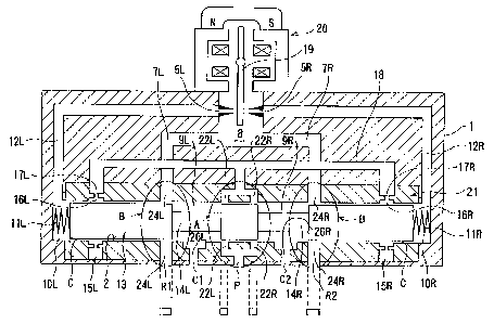
As shown in FIG. 1, the hydraulic servovalve has a sleeve
21 disposed in a valve body 1 and having a spool hole 2 which
houses a spool 13 axially movably therein. Opposite end
portions of the spool 13 are supported by respective
hydrostatic bearings 15L, 15R between the spool 13 and the
' ' 21g~23
sleeve 21. The hydrostatlc bearlngs 15L, 15R comprlse
respectlve pockets 16L, 16R and respectlve orlflces 17L, 17R
whlch are defined in the sleeve 21.
The sleeve 21 has rectangular wlndows 22L, 22R
5 communlcating with the supply port P and the passage 18,
rectangular windows 24L, 24R communicating with the respective
return ports Rl, R2 and the respective passages 7L, 7R, and
passages 26L, 26R communicating with the respective control
ports Cl, C2. Actually, there are four rectangular windows 22L
10 defined as one ci-L:ull,rerw-Clal array in the sleeve 21, four
rectangular windows 22R defined as one clrcumferentlal array in
the sleeve 21, four rectangular windows 24L defined as one
circumferential array in the sleeve 21, and four rectangular
windows 24R defined as one circumferential array in the sleeve
15 21. FIG. 2 shows the sleeve 21 to be housed in the valve body
1 and the spool 13 to be housed in the sleeve Zl. The æhape
and number of these windows are not limited to the illustrated
shape and number, but may be changed depending on the required
performance of the hydraulic servovalve. In FIG. 2, the
20 corresponding ~ A, B are shown.
A worklng fluld sl~ppl ~Pd from the supply port P ls
lntroduced through the wlndow 22L and the passage 26L into the
control port Cl or through the window 22R and the passage 26R
into the control port C2, ~9P~Pn~n~ on the direction in which
25 the spool 3 is axially moved. The working fluld from the
supply port P ls also supplled through the passage 18 to the
hydrostatic bearings 15L, 15R. The working fluid which has
passed through the control port Cl is supplied to a load, then
218~023
flows through the control port C2 and the window 24R to the
return port R2. The working fluid which has passed through the
control port C2 is supplied to a load, then flows through the
control port C1 and the window 24L to the return port Rl.
The flow rate of the working fluid can be controlled by
adfusting the ~;r c:1nnq of the rectangular windows 22L, 22R,
24L, 24R, without using the spool 13 having an extremely small
diameter. Therefore, when the hydraulic servovalve is to be
~l~c1gn~1 to handle small control flow rates, the ~ c1nnc of
the spool 13 are not required to be unduly reduced, and hence
the spool 13 can be r-^h1 n~ri with ease.
FIGS. 3A and 3B are views for explaining flows of a
working fluid in the conventional hydraulic servovalve shown ln
FIG. 10. FIG. 3A is a schematic view showing the hydraulic
servovalve in which the spool 13 is moved rightward, and FIG.
3s is a system diagram showing flows of a working fluid in the
state shown in FIG. 3A.
As shown in FIG. 3A, the working fluid supplied from the
supply port ~ is branched into two f lows along two paths .
Along one of the paths, the working fluid flows through the
control ori f ice Al and the control port Cl into the load ( an
actuator ) connected to the control port Cl, and the working
fluid returns to the control port C2 from the load. Then, the
working fluid flows through the control orifice B2 into the
return port R2. Along the other path, the working fluid flows
through the passage 18, the llydlu,l cLtic bearing 15R and the
annular clearance C between the spool 13 and the lnner
circumferential surface of the spool hole 2 into the annular
11
~ 8~23
groove 4R from fully circumferentially around the spool 13, and
then the working fluid flows through the annular groove 4R into
the return port R2.
As shown in FIG. 3B, while the working fluid is flowing
5 along one of the paths, a pressure Ps of the working fluid
supplied from the supply port P is changed into a pressure Pa
after passing through the orifice A1, and the pressure Pb which
is a pressure at the outlet of the load is changed into a
pressure Pt after passing through the orifice a2. While the
10 working fluid is flowing along the other path, the pressure Ps
of the working fluid supplied from the supply port P is changed
into a pressure Pp after passing through an orifice D of the
llydr u-il,aL,lc bearing 15R, and the pressure Pp is changed into
the pressure Pt after passing through the annular clearance C.
FIG. 4A is a schematic view showing the hydraulic
servovalve of FIG. 1 in which the spool 13 is moved rightward.
The hydraulic servovalve in FIG. 4A has the control ports
Cl and C2 whlch are the same routes as the conventional valve,
but ls different from the conventlonal valve in that the
20 control orifices A and B are defined not by openings formed
fully circumferentially around the spool but by the rectangular
windows 22L and 24R. On the other hand, the working fluid
flowing into the hydrostatic bearing 15R flows therethrough,
and through the annular clearance C between the spool 13 and
25 the inner circumferential surface of the spool hole 2 and the
window 24R into the return port R2.
As shown in FIG. 4B, while the working fluid is flowing
along one of the paths, a pressure Ps of the working fluid
12
2~81~3
supplied from the supply port P is changed into a pressure Pa
after passing through the orifice A, and the pressure Pa is
changed into a pressure Pb through the load. While the working
fluid is flowing along the other path, the pressure Ps of the
5 working fluid supplied from the supply port P is changed into
a pressure Pp after passing through an orifice D of the
hydrostatlc bearing 15R, and the pressure Pp is changed into
the pressure Pb af ter passing through the annular clearance C .
The working fluid flowing from the annular clearance C under
10 the pressure Pb then is, ' ;n~-l with the working fluid flowing
from the load under the pressure Pb. The pressure Pb of the
i n~tl working fluid is then changed into the pressure Pt
after passing through the control orifice 13. At this time, the
working fluid may possibly develop a back pressure between the
15 hydrostatic bearing 15R and the return port R2.
If a back pressure is developed between the pockets 16L,
16R of the lly-llu~ tic bearings 15L, 15R and the return ports
R1, R2, then a differential pressure ~Pbrg (= Ps - Pp) is
reduced, unduly lowering a load capacity of the llyd~ lc
20 bearings 15L, 15R. Therefore, the hydrostatic bearings 15L,
15R may not be sufficiently effective to move the spool 13
smoothly out of contact with the sleeve 21.
If the spool and the sleeve are co-axial, the pressure Pp
in all of the pockets 16R are equal one another as shown in
25 FIG. 5A. If the spool and the sleeve are not co-axial, the
pressure in the pocket 16R to which the spool 13 comes closer
becomes higher than that in the opposite pocket 16R from which
the spool 13 becomes away. That is, the pressures in the
13
218~23
pockets 16R, 16R 180 opposite each other become Pp+~Pp and Pp-
~Pp, respectively as shown in Fig. 5B. The differential
pressure ~Pp acts to force back the spool 13 to the central
position. Therefore, the higher the pressure ~Pp rlses, the
5 larger the load capacity of the lly~r ~.:3L~tic bearing grows.
When the spool is brought in contact with the sleeve, the
pressure in the pocket at the contacting side becomes a certain
pressure which is almost the same as the pressure Ps. At this
time, since the pressure ~Pp can be the pressure ~Pbrg, the
10 higher the pressure ~Pbrg rises, the larger the load capacity
grows. Therefore, if the back pressure is developed between
the pocket 16R and the return port R, the pressure Pp in the
pocket 16R comes closer to the supply pressure Ps, and the
pressure ~Pbrg becomes smaller, resulting in lowering the load
15 capacity of the hydrostatic bearing.
FIG. 6 shows a hydraulic servovalve according to another
embodiment of the present invention, which is designed to
prevent the load capacity of the hydrostatic bearings 15L, 15R
from being unduly lowered. The hydraulic servovalve shown in
20 FIG. 6 differs from the hydraulic servovalve shown in FIG. 1 in
that the sleeve 21 has rectangular windows 27L, 27R
r ~n; F~ting with the chambers 9L, 9R, respectively, and
annular grooves 28L, 28R extending fully circumferentially
around the spool 13 and held in, ;-~tion with the
25 hydrostatic bearings 15L, 15R, respectively through the annular
clearance C.
To be more specific, the hydraulic servovalve shown in
FIG. 6 has fluid pa~i~dy~w~ly:i extending from the control ports
14
2~ 2~
Cl, C2 respectively through the passages 26L, 26R and the
windows 27L, 27R to the respective return ports Rl, R2, i.e.,
fluid passageways connecting the respective control ports and
the respective return ports, and fluid p~A~ways extending
5 from the hydrostatic bearings 15L, 15R respectively through the
annular clearances C and the annular grooves 28L, 28R to the
respective return ports Rl, R2, i.e., fluid passageways
connecting the respective hydrostatic bearings and the
respective return ports.
FIG. 7A shows flows of a working fluid in the hydraulic
servovalve shown in FIG. 6. As shown in FIG. 7A, a working
fluid flows from the supply port P under a pressure Ps, and is
dlvided into a control flow Qa, a control flow Qb, and flows
Qbrg toward the hydrostatic bearings 15L, 15R. From the
hydrostatic bearings 15L, 15R, the flows Qbrg pass through the
annular clearance C between the outer circumferential surface
of the spool 13 and the inner circumferential surface of the
sleeve 21 and the ann~lar grooves 28L, 28R to the return ports
Rl, R2.
To be more specific, a fluid passageway communicating
between the control port and the return port and a fluid
passageway ;r~ting between the hydlu,~tic bearing and
the return port are independently formed in the sleeve.
Therefore, pressures of the working fluid flowing through the
above two pas~ageways are not affected from each other. That
is, as shown in FIG. 7~, while the working 1uid is flowing
along one of the paths, a pressure Ps of the working fluid
supplied from the supply port P is changed into a pressure Pa
132~
after passing through the orifice A, and the pressure Pa is
changed into a pressure Pb through the load. Then, the
pressure Pb is changed into a pressure Pt after passing through
the control orifice B. While the working fluid is flowing
5 along the other path, the pressure Ps of the working fluid
supplied from the supply port P is changed into a pressure Pp
by an orifice D of the hydrostatic bearing 15R, and the
pressure Pp is changed into the pressure Pt after passing
through the annular clearance C. The working fluid flows
10 through two separate flow passageways into the return port R2.
The hydraulic servovalve in FIG. 6 is different from the
conventional hydraulic servovalve in that the control orifice
A and the control orifica B are formed by the rectangular
windows .
When the working fluid flows from the llydlO~ tic bearings
15L, 15R respectively through the annular clearance C and the
annular grooves 28L, 28R to the respective return ports R1, R2,
by providing the flow of the working fluid from fully
circumferentially around the spool 13 not through any
20 rectangular orifices (rectangular windows ) but through the
annular grooves 28L, 28R, the differential pressure ~Pbrg (5 Ps
- Pp ) is prevented from being reduced. As a result, the
hydrostatic bearings 15L, 15R remain sufficiently effective to
move the spool 13 smoothly out of contact with the sleeve 21.
25 Accordingly, the annular grooves 28L, 28R are effective to
enable the hydrostatic bearings 15L, 15R to automatically
center the spool 13 in the sleeve 21.
With the structure of the hydraulic servovalve shown in
16
023
FIG. 6, the hydrostatic bearings 15L, 15R can provide a
sufficient bearing effect in a hydraulic servovalve which
handles relatively small control flows Qa, Qb and has
rectangular windows (rectangular orifices) in the sleeve. - ~
The hydraulic servovalve shown in FIG. 1 still has a
problem in the case that the dimension of the windows is formed
to be t~ .L~ ly small. FIG. 8A shows characteristics of the
hydraulic servovalve having extremely small windows, and FIG.
8B shows characteristics of the hydraulic servovalve shown in
FIG. 6. The hydraulic servovalve in FIG. 8B has the same
n of the windows as that in FIG. 8A. In each of FIGS.
8A and 8B, the hori~ontal axis represents an input signal Vi
(V) supplied to the tor~Iue motor 20 for actuating the flapper
19, and the vertical axis represents a spool displacement
signal Vy (V) indicative of the axial displacement of the spool
13. In each of FIGS. 8A and 8B, the pressure Ps of the working
fluid flowing from the supply port P is 140 bar.
With the hydraulic servovalve shown in FIG. l, as shown in
FIG. 8A, the spool ~{'~pl~ t signal Vy (V) is not llnear to
the input signal Vi, but exhibits a certain degree of
hysteresis. Therefore, the spool 13 is not highly responsive
to the input signal Vi, and does not move smoothly in the spool
hole 2. With the hydraulic servovalve shown in FIG. 6, as
shown in FIG. 8B, the spool ~l;q~ nt signal Vy (V) is
linear to the input signal Vi, and exhibits no hy,~lel.lc
~LI_~pel I,y . Therefore, the spool 13 is highly responsiYe to the
input signal Vi, and moves smoothly in the sleeve 21 due to the
bearing effect produced by the llydl~ tic bearings 15L, 15R.
17
~81023
FIG. 9 shows a hydraulic servovalve according to still
another embodiment of the present invention. The hydraulic
servovalve shown in FIG. 9 differs from the hydraulic
servovalve shown in FIG. 6 in that the working fluid is
5 supplied to the hydrostatic bearings 15L, 15R through a passage
18' defined centrally in the spool 13. The other details of
the hydraulic servovalve shown in FIG. 9 are the same as those
of the hydraulic servovalve shown in FIG. 6, and will not be
described in detail below.
Although certain preferred embodiments of the present
invention have been shown and described in detail, it should be
understood that various changes and modifications may be made
therein without departing from the scope of the appended
claims .
18