Sélection de la langue

Search

Sommaire du brevet 2181434 

Énoncé de désistement de responsabilité concernant l'information provenant de tiers

Une partie des informations de ce site Web a été fournie par des sources externes. Le gouvernement du Canada n'assume aucune responsabilité concernant la précision, l'actualité ou la fiabilité des informations fournies par les sources externes. Les utilisateurs qui désirent employer cette information devraient consulter directement la source des informations. Le contenu fourni par les sources externes n'est pas assujetti aux exigences sur les langues officielles, la protection des renseignements personnels et l'accessibilité.

Disponibilité de l'Abrégé et des Revendications

L'apparition de différences dans le texte et l'image des Revendications et de l'Abrégé dépend du moment auquel le document est publié. Les textes des Revendications et de l'Abrégé sont affichés :

  • lorsque la demande peut être examinée par le public;
  • lorsque le brevet est émis (délivrance).
(12) Demande de brevet: (11) CA 2181434
(54) Titre français: ACTUATEUR FACILITANT L'ATTELAGE D'UN OUTIL A UN TRACTEUR
(54) Titre anglais: ACTUATOR FOR AIDING HITCHING OF AN IMPLEMENT TO A TRACTOR
Statut: Réputée abandonnée et au-delà du délai pour le rétablissement - en attente de la réponse à l’avis de communication rejetée
Données bibliographiques
(51) Classification internationale des brevets (CIB):
  • A01B 59/043 (2006.01)
  • A01B 59/041 (2006.01)
  • A01B 59/06 (2006.01)
(72) Inventeurs :
  • PELTOLA, TUOMO (Finlande)
(73) Titulaires :
  • IITIN KYMPPIKONEISTUS OY
(71) Demandeurs :
  • IITIN KYMPPIKONEISTUS OY (Finlande)
(74) Agent: MCCARTHY TETRAULT LLP
(74) Co-agent:
(45) Délivré:
(86) Date de dépôt PCT: 1995-01-25
(87) Mise à la disponibilité du public: 1995-08-03
Licence disponible: S.O.
Cédé au domaine public: S.O.
(25) Langue des documents déposés: Anglais

Traité de coopération en matière de brevets (PCT): Oui
(86) Numéro de la demande PCT: PCT/FI1995/000035
(87) Numéro de publication internationale PCT: FI1995000035
(85) Entrée nationale: 1996-07-17

(30) Données de priorité de la demande:
Numéro de la demande Pays / territoire Date
U940055 (Finlande) 1994-01-28

Abrégés

Abrégé français

Dispositif actuateur facilitant l'attelage d'un outil (1) au système d'attelage trois points d'un tracteur (2) ou d'un véhicule analogue. Ce dispositif actuateur comporte un vérin hydraulique à double effet (5) monté entre deux bielles (3) du système d'attelage trois points du tracteur, et destiné à régler la distance comprise entre les bielles de traction (3), ledit vérin hydraulique (5) étant raccordé à un groupe de vannes de distribution à deux voies (4) du système hydraulique du tracteur. Dans le but d'éviter toute surcharge mécanique des bielles de traction (3), le piston du vérin (5) est installé avec un certain jeu radial formant un passage interne de dérivation.


Abrégé anglais


The present invention relates to an actuator device
for aiding the hitching of an implement (1) to the three-
point linkage of a tractor (2) or similar pulling vehicle.
According to the invention, the actuator device comprises
a double-acting hydraulic cylinder (5), which is mountable
between two pulling links (3) of the tractor's three-point
linkage for controlled adjustment of the mutual distance
between the pulling links (3), and said hydraulic cylinder
(5) is connectable to a two-way directional control valve
bank (4) of the hydraulic system of the tractor. To avoid
mechanical overload of the pulling links (3), the cylinder
(5) is manufactured with a piston clearance providing an
internal bypass flow path.

Revendications

Note : Les revendications sont présentées dans la langue officielle dans laquelle elles ont été soumises.


Claims:
1. An actuator device for aiding hitching of an implement
(1) to a three-point linkage of a tractor (2) or similar
pulling vehicle by means of a hydraulic cylinder system for
controlled adjustment of the mutual distance between the
pulling links (3 ), characterized in that a double-acting
seal-less hydraulic cylinder-piston device (5) is connected
to a two-way directional control valve bank (4) of the
hydraulic system of the tractor and mounted transversally
between two pulling links (3) of the tractor's three-point
linkage.
2. An actuator device as defined in claim 1, characterized
in that the hydraulic cylinder (5) is provided with a
clearance of approx. 0.1 to 0.2 mm between the cylinder
inner wall and the piston.
3. An actuator device as defined in claim 1, characterized
in that the hydraulic cylinder-piston device (5) is
detachably connected to the pulling links (3) of the
tractor (2) by means of quick-release joints mounted to the
ends of said pulling links (3).

Description

Note : Les descriptions sont présentées dans la langue officielle dans laquelle elles ont été soumises.

4~ 7 ~38-- r ~, I / r ~ n7e,~ C~
~CTUATOR FOR AIDINO nl.. OF AN IMPL~ T TO A TR~CTOR
~he pre~i~nt invention rela~l3~ to an ~ctuato~ Lnt~nde~ to
a~d hltohing o An ~ ~rl ~ l~ tC a ~ 9 p~lnt llnkns~l~ of a
traotor cr ~imll~r pullinc ~ehLcLe ~y m~n3 of a hydr~ulic
cyl~nd~r y~;tl~m ~or controlled ~a~u3~ment of the mutual
di~t~nc~ tw~n the pullin~ llnk~.
With th~ gr~t~r 3~ze and ~7c~ght of modern equipment, th~
u~ oving of ~ractor3 c~ weLl ~as i ~pL~ n~ haY baco~e ~ces-
alvely ~ t~id. Con~equ~ntly, s~roper loo~tion o th~
tr~otor ~nd th~ ~ual l~ltching o~ th~ implnm~nt ~ullins
llnk~5ie c~n ke an ~ ,L~ .~ly dlfficult and ev~r. potentl~lly
cl2hsr~rous operation, wh:ich ,..o, e:OV~L illi tim~-~onsuminSI.
~5
In D~ 1 557 84~ ~here ~s ~l~clo~ed an a~L~r-v- ~ ~or
~Idln~ to coup~e cn ~ t to the pulling llnkY o~ c
tr~ctor. ~h~ known 4_~.CI15,~ compri~es two ~lr.gle stroke
cyiinde~s, ~}~ch couplod between the frame OI' th~ trac~or
2~ and on~ ~ulling link. Irl orter to adm~ t ~ lat~r^l m ~ "t
o~ th~ pullln~ lir~ks wlt:h u~ n~ed mutual d$3t~nce when
th~ flu$d connsc:t~on o~ th- cylinders to ~ hy~rAulic pump
and a return plpe i~ int~3rrupt-d there i~ 8 iluld connec~
ti~n ~ntwean th~ two cylind~rs. This known a~
2s requlre!s at l~a~t t~o s~p~r~5t~ lve~ ~o ~e controlled
lnd~vidually, two ~t~ion~rily nwunted hydr~ulio cylin~r~
~nd ~ nyln~ ho~e3, re~ultlng ln ~ rel~tlvely
complic~te~ con~tructlon.
30 It 1~ ~n o~eot of th~3 ~r~lsnt in~ention to uv-.~ . s ~uoh
pro~lems and to obt~in a mor~ ~implifi~d nnd sconomio
con~ruction by virtue ~ an aatu~tor devi~- b~lng oharac-
t~rlzod ln ~hat a doubla~-~ctln~ s~ hydraulic
~ylin~ r-piaton devic~ 13 ~v~ .d to a two-way direc-
35 tional con~rol v~l~7n ban~ o~ the hy~rnulic ~y~te~ of thetractor and l~wunted LL~ VQL~a11Y ~tween two pulling llnks
o~ the t~actor ' ~ three-p~ nt link~g~ .
AMENDED SHE~

U"~ o~ L . 3~ ga ll~ 4~ 7~8~- ~CT/Fi95 i~035
I Th~ Swe~l-h Patent omeo
o PCT 11 . n~lAppl~c~on ¦ t 4
1~ ~18143~
Wlth th~ hel~ of the ~ctuatcr devlce ;~ccordinSI to th~3
lnventlon, hltchlng o~ th~ 1 1~ t c~n b~ c~rrl~d out
wlthout th~ n~d ~or t~ drlv~r to lu~v~ the c~bln ~or
hitchlnq, s~ince tha ~unc ticn o~ thQ hydr~ullc cyllr~der czm
5 b~ controll~d ~y th~ contrcl 113vor~ o~ thl~ tr~ctor's
hydr~ullc ~yst~m~ wh~ ch ~re lc ca~eld lrl th~ tractor c~bin
~h3 ne~ lQrs hydr~ulic cylinder-pi~ton d~vice prevQnts
effectivQly excennive lo~d on the pullin~F links ~nd it
permit~ ~ ~lontlnS~ 1 of thff pulling li~k~ durlng thQ
1C timQ th~a hydr~ulic cylind~r i- not i5 po~r-d
It has ~ n ~shown that a pref~red ~ n of cle~r~nc6
l~tw~eln th~ cylind-r lnn~r Prell ~nd th~ plston i~ ~pprox
0 10 to 0 20 mm
Fur~hor ch~racterlstic~ of thc preqent Lnventlon
~pe~r ~om the qnt~l on~d clslms
... .. .., ... . . ~ . . . .. -
C~wing to the Rimpl~ con;~truction of the ~ctuat~r a~vice
2~ ~ccording to the invQntLon, the devicQ i~ ~n' 1 y dur~ble
and reli~bl~ lr U8~.
.
AMEN~IEP 'SI IEEI

2;L8~3~
WO 95/20311 - r~
The inventlon will now be (~ r~ hed in greater detail with
L~Le~ oe to the appended drawings, in which:
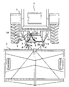
Figure 1 is a peLx~ Llve vlew of an a~;LuaLu~ device
- s according to the invention mounted to a tr2ctor; and
Figure 2 is a top view of the a~,LuaLuL device illustrated
in Fig. 1 with an ~ t hitched to the pulling links.
to With reference to Fig. 1, the actuator device according to
the invention for aiding the hitching of an 1 ,1~ L 1 to
the three-point linkage of a tractor 2 or similar pulling
vehicle comprises a double-acting hydraullc cylinder 5,
which is mountable between two pulling links 3 of the
15 three-point linkage of the tractor 2 for controlled
adjustment of the mutual distance between the pulling
links, which hydraulic cylinder is culllleuLable to a two-way
directional control valve bank 4 of the tractor ' s hydraulic
system .
To perform its function, the hydraulic cylinder 5 is
mounted between the two parallel pulling links 3 of the
tractor 2 so that its cylinder portion 5a is connected to
one pulling link 3, while its piston rod 5b is connected to
2s the opposlte pulling link 3. The hydraulic cylinder 5 is
adapted to be powered by the conventional hydraulic system
of the tractor via two hydraulic oil hoses 6 connected to a
two-way directional control valve bank 4 of said hydraulic
system, said hoses 6 advt,L~ y~uu8ly being attached to said
30 control valve bank 4 by means of quick-release uun..eu L
6a. By vlrtue of this alL~ t, the operation of the
hydraulic cylinder 5 can then be controlled by control
levers located in the tractor cabin 7 of the tractor as a
standard a~ f P~ y of the tractor.
3s
To achieve a L:unL7LLuuL~on which is r-x~r-l ly simple and
safe in use, the hydraulic cylinder 5 is advcl-.Lc.y~uusly

W0 95/20311 ~ 1 8 ~ ~ 3 4 ~ rL ~ .
manufaetured with an approx. O.lO - 0.20 mm clearance
between the eylinder inner wall and the piston without
using any seal to bridge the clearance. Then, the piston
can be advc,-l cy~ously manufactured from a bearing alloy.
5 This CL L Clly. l. ensures that the piston inherently
provides a bypass ehannel for a eertain amount of hydraulie
oil thus preventing exeessive load on the pulling links 3
notwithstanding the direct connection of the hydraulic
cylinder to the tractor ' s hydraulic system without using
lo any pressure reducing means . Such an aL L Cll~ . also
permits floating movement of the pulling links 3 during the
time the hydraulic cylinder 5 is not powered.
The mounting of the hydraulic cylinder can be '1f~rl so
15 as to cause minimal disturbance to the use of the power
take-off shaft of the tr~ctor.
By providing the pulling links 3 of the tractor 2 with
cluick-release ~oints, the hydraulic eylinder S ean be made
20 easily detachable and transferrable to another tractor 2
having compatible cylinder end ~oints.
With Lt:feL~~ to Fig. 2, the function of the actuator
device according to the inventlon is as follows. To hitch
2s an i, l~ t 1 to the three-point linkage of a tractor 2,
the tractor 2 is initially Lt!v~:L:~ed in front of the
, l ~ t l and the pulling hole 8 of one pulling link 3 of
the tractor linkage is aligned with the compatible pulling
pin 9 of the im;ll~ t. I~ext, the hydraulic cylinder 5 is
30 activated by operating t~le control lever of the control
valve bank 4 so that the hydraulic cylinder 5 is powered to
actuate the pulling links 3 with a pulling force. Then, the
pulling link 3 is moved toward the pulling pin 9 of the
~mrl t l so as to locate the pin through the pulling
35 hole 8 of the pulling lir~k 3. With the pulling pin 9 now
engaged in the pulling hc~le 8, the pulling links 3 of the
tractor are lifted at a moderate force by operating another

Wo 9S/20311 ;~ ~ 8 1 ~ 3 ~ r~llr~
control lever of the tractor hydraulic system until the
frlction of the pin in the hole ls sl~ff~t~1t~nt to keep the
pulling pin 9 of the ~ l~ L in place in the pulling hole
8 during the ~ubseyuellt hitching step of the 1 l~ L.
5 Tn this step, the hydraulic cylinder 5 is controlled to
zctuate in the opposite direction so that the pulling links
3 are forced to away from each other. Next, the pulling
hole 8 of the opposite side pulling link 3 is aligned in
front of the mating pulling pin 9 of the 1, l~ L, after
10 which the hydraulic cylinder 5 is powered to actuate a
pulling force between the links. Then, the opposite side
link 3 is moved toward the pulling pin 9 of the ~ mrl L
so as to locate the pin through the pulling hole 8 of the
pulling link 3. After the hitching of the 1, l L is
15 saiely and easily ~t ~ Rhe~l in the above-described
manner, the driver can leave the cabin 7 and secure the
t by inserting securing pins into holes drilled to
the ends of the pulling pins 9 of the ~ mrl t .
20 To prevent undesirable lateral swing of the pulling links
3, both sides of the tractor 2 can be provided with
conventional lateral ~ L limiters 10 adapted between
the tractor chassis ~md said pulling link 3.
By virtue of the invention, the unhitching of the ~mrl L
l from the pulling links 3 of the tractor i8 made e~Ll~ ly
8imple. After the securing pins are removed from the ends
of the pulling pins 9, the pulling pins 9 can be released
from the pulling links 3 by controlling the hydraulic
30 cylinder 5 to push the pulling links apart from each other.

Dessin représentatif
Une figure unique qui représente un dessin illustrant l'invention.
États administratifs

2024-08-01 : Dans le cadre de la transition vers les Brevets de nouvelle génération (BNG), la base de données sur les brevets canadiens (BDBC) contient désormais un Historique d'événement plus détaillé, qui reproduit le Journal des événements de notre nouvelle solution interne.

Veuillez noter que les événements débutant par « Inactive : » se réfèrent à des événements qui ne sont plus utilisés dans notre nouvelle solution interne.

Pour une meilleure compréhension de l'état de la demande ou brevet qui figure sur cette page, la rubrique Mise en garde , et les descriptions de Brevet , Historique d'événement , Taxes périodiques et Historique des paiements devraient être consultées.

Historique d'événement

Description Date
Inactive : CIB de MCD 2006-03-12
Le délai pour l'annulation est expiré 1999-01-25
Demande non rétablie avant l'échéance 1999-01-25
Réputée abandonnée - omission de répondre à un avis sur les taxes pour le maintien en état 1998-01-26
Demande publiée (accessible au public) 1995-08-03

Historique d'abandonnement

Date d'abandonnement Raison Date de rétablissement
1998-01-26
Titulaires au dossier

Les titulaires actuels et antérieures au dossier sont affichés en ordre alphabétique.

Titulaires actuels au dossier
IITIN KYMPPIKONEISTUS OY
Titulaires antérieures au dossier
TUOMO PELTOLA
Les propriétaires antérieurs qui ne figurent pas dans la liste des « Propriétaires au dossier » apparaîtront dans d'autres documents au dossier.
Documents

Pour visionner les fichiers sélectionnés, entrer le code reCAPTCHA :


Pour visualiser une image, cliquer sur un lien dans la colonne description du document. Pour télécharger l'image (les images), cliquer l'une ou plusieurs cases à cocher dans la première colonne et ensuite cliquer sur le bouton "Télécharger sélection en format PDF (archive Zip)" ou le bouton "Télécharger sélection (en un fichier PDF fusionné)".

Liste des documents de brevet publiés et non publiés sur la BDBC .

Si vous avez des difficultés à accéder au contenu, veuillez communiquer avec le Centre de services à la clientèle au 1-866-997-1936, ou envoyer un courriel au Centre de service à la clientèle de l'OPIC.


Description du
Document 
Date
(aaaa-mm-jj) 
Nombre de pages   Taille de l'image (Ko) 
Abrégé 1995-08-02 1 48
Dessins 1995-08-02 2 45
Revendications 1995-08-02 1 31
Description 1995-08-02 5 207
Dessin représentatif 1997-07-01 1 12
Courtoisie - Lettre d'abandon (taxe de maintien en état) 1998-02-22 1 187
Taxes 1996-07-16 1 44
Rapport d'examen préliminaire international 1996-07-16 7 147