Sélection de la langue

Search

Sommaire du brevet 2182552 

Énoncé de désistement de responsabilité concernant l'information provenant de tiers

Une partie des informations de ce site Web a été fournie par des sources externes. Le gouvernement du Canada n'assume aucune responsabilité concernant la précision, l'actualité ou la fiabilité des informations fournies par les sources externes. Les utilisateurs qui désirent employer cette information devraient consulter directement la source des informations. Le contenu fourni par les sources externes n'est pas assujetti aux exigences sur les langues officielles, la protection des renseignements personnels et l'accessibilité.

Disponibilité de l'Abrégé et des Revendications

L'apparition de différences dans le texte et l'image des Revendications et de l'Abrégé dépend du moment auquel le document est publié. Les textes des Revendications et de l'Abrégé sont affichés :

  • lorsque la demande peut être examinée par le public;
  • lorsque le brevet est émis (délivrance).
(12) Demande de brevet: (11) CA 2182552
(54) Titre français: METHODE DE COUPAGE AU LASER
(54) Titre anglais: LASER CUTTING OF MATERIALS
Statut: Réputée abandonnée et au-delà du délai pour le rétablissement - en attente de la réponse à l’avis de communication rejetée
Données bibliographiques
(51) Classification internationale des brevets (CIB):
  • B23K 26/067 (2006.01)
(72) Inventeurs :
  • O'NEILL, WILLIAM (Royaume-Uni)
(73) Titulaires :
  • THE BOC GROUP PLC
(71) Demandeurs :
  • THE BOC GROUP PLC (Royaume-Uni)
(74) Agent: GOWLING WLG (CANADA) LLP
(74) Co-agent:
(45) Délivré:
(22) Date de dépôt: 1996-08-01
(41) Mise à la disponibilité du public: 1997-02-06
Licence disponible: S.O.
Cédé au domaine public: S.O.
(25) Langue des documents déposés: Anglais

Traité de coopération en matière de brevets (PCT): Non

(30) Données de priorité de la demande:
Numéro de la demande Pays / territoire Date
9516099.0 (Royaume-Uni) 1995-08-05

Abrégés

Abrégé anglais


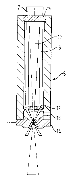
An apparatus for cutting a workpiece comprises optical means 4 located in a single
cutting head 6 for splitting a beam of laser energy into two separate beams 8, 10.
The cutting head 6 includes an inlet 16 for oxygen under pressure and a nozzle 14
for the outlet of the oxygen. At least one split beam 8 is focused at a location above
the surface of the workpiece such that when in use the area on the surface of the
workpiece impinged by the split beam 8 is greater than the area being impinged
upon by the oxygen when leaving the nozzle 14.

Revendications

Note : Les revendications sont présentées dans la langue officielle dans laquelle elles ont été soumises.


-6-
CLAIMS
1. An apparatus for cutting a workpiece comprising a source of laser energy,
optical means for splitting a beam of laser energy when emanating from said
source into two separate beams and focusing each beam when so split at a
predetermined location relative to the workpiece, one beam having a greater
depth of focus than the other beam, characterised in that the optical means is
located in a single cutting head which includes an inlet for oxygen or an
oxygen rich gas under pressure and a nozzle for the outlet of the oxygen or
oxygen rich gas, at least one beam being focused at a location above the
surface of the workpiece such that when in use the area on the surface of the
workpiece impinged by said one beam is greater than the area being
impinged upon by the oxygen or oxygen rich gas when leaving the nozzle.
2. An apparatus as claimed in Claim 1, in which the optical means includes a
diffractive optical element located at one end of the cutting head for splittingthe beam of laser energy into the two separate beams, one split beam being
directed towards a lens located adjacent the opposite end of the cutting head
which focuses said one split beam at a location above the surface of the
workpiece; the remaining split beam being focused by the diffractive optical
element such that it passes unaltered through the lens.
3. An apparatus as claimed in Claim 1, in which the optical means includes a
double element lens located at one end of the cutting head for splitting the
beam of laser energy into the two separate beams one split beam being
directed towards a lens-located adjacent the opposite end of the cutting head
which focuses said one split beam at a location above the surface of the
workpiece; the remaining split beam being focused by the double element
lens such that it passes unaltered through the lens.

-7-
4. An apparatus as claimed in any one of Claims 1 to 3 in which the nozzle is
attached to the cutting head at an end immediately adjacent the workpiece.
5. An apparatus as claimed in any one of Claims 1 to 4 in which said one split
beam is focused at a point within the nozzle the remaining split beam being
focused at a point at or below the surface of the workpiece.
6. An apparatus for cutting a workpiece constructed, arranged and adapted to
operate substantially as hereinbefore described with reference to and as
illustrated in Figure 1, Figure 2 or Figure 3 of the accompanying drawings.

Description

Note : Les descriptions sont présentées dans la langue officielle dans laquelle elles ont été soumises.

21 82552
95B1 25/PG -1-
LASER CU-rTlNG OF MATERIALS
The present invention relates to metllods of and apparatus for cutting materials and
in partlcular the cutting of thick sectioned steel using a low power laser cutter.
A laser cutting process is known in ~hich a relatively high power laser beam is
focused onto the surface of a material to be cut. The laser energy sustains the
material at its melting point and a high speed gas jet blows away the molten material
to produce a cut. This known process provides the laser energy throughout the
depth of the cut and thus requires a l1igh power good quality beam in order to
produce an ~cc~ cut.
European Patent Publication Number 0458180 descnbes a method of cutting a
workpiece using a laser beam and a high pressure gas stream both being directed
through a nozzle. The focal point of the laser beam is located at a distance above
the surface of the workpiece to be cut such that it strikes the surface as a
de-focused beam. This together with a high pressure oxygen or
oxygen rich gas jet produces, clean, sharp edges and a high quality surface finish on
the cut face.
US Patent 3604890, describes a laser cutting system in which a beam of laser
energy is caused to impinge on a partially silvered reflective surface so that it is split
into two separate beams. Each bearrl is subsequently focused by an indiYidual lens
system such that one beam is focused at a point S~:,ld~ 'y at the surface of theworkpiece to be cut, whilst the second beam is focused on said point and over a
depth of focus larger than the depth of focus of said first beam. Each lens system is
located in lts own ..~s.~ d cutting l1ead which includes a gas inlet for directing
gas under pressure onto the area of the workpiece where the ,~co~ d beam is
focused. The use of two lens systems and two cutting heads renders the cutting
system l,U~ and expensive tc manufacture and to set up particularly for
profile cutting.

2 1 82552
95B1 25/PG -2-
lt is an aim of the present invention to improve the efiiciency of low power laser
cutting particuiarly of thick sectioned steel by splitting a laser beam such that one
spiit beam has a greater depth of focus than the other split beam.
According to the present invention, an apparatus for cutting a workpiece comprises
a source of laser energy, optical means for splitting a beam of laser energy when
t:llldlld~ill9 from said source into two separate beams and focusing each beam when
so split at a ~ d~L_llllill~i location relative to the workpiece. one beam having a
greater depth of focus than the other beam and in which the optical means is located
in a single cutting head which includes an inlet for oxygen or an oxygen rich gas
under pressure and a nozzle for the outiet of the oxygen or oxygen rich gas, at least
one beam being focused at a locatiol1 above the surface of the workpiece such that
when in use the area on the surface of the workpiece impinged by said one beam is
greater than the area being impingecl upon by the oxygen rich gas when leaving the
nozzle.
In one t:",L"~ ii",elll of the invention, the optical means includes a diffractive optical
element located at one end of the cutting head for splitting the beam of laser energy
into the two separate beams one split beam being directed towards a lens locatedadjacent the opposite end of the cutting head which focusessaid one split beam at a
location above the surface of the ~.olh~ c~, the remaining split beam being focused
by the diffractive optical element sucll that it passes unaltered through the lens.
In an alternative ~I~ liJo~iill,e"~, the optical means includes a double element lens
located at one end of the cutting head for splitting the beam of laser energy into the
two separdte beams one split beam t~eing directed towards a lens located adjacent
the opposite end of the cutting head ~Nhich focuses said one split beam at a location
above the surface of the ~oi k,uitl~ , the remaining split beam being focused by the
double element lens such that it passes unaltered through the lens.

21 ~2~52
95B1 251PG -3-
[r~ od;~ La of the invention will no~v be described by way of example, referencebeing made to the Figures of the a~,b,,~"",a"ying didyldlllllldli~ drawings in which:-
Figure 1 is a schematic cross-section through the cutting head of a laser cutting
apparatus;
Figure 2 is a schematic cross-section through the cutting head of Figure 1 but
illustrating the split beams being focused at spaced apart locations; and
Figure 3 is a schematic cross-section through an alternative cutting head of a laser
cutting apparatus.
As shown in Figure 1, a laser beam 2 t:llldlldiill9 from a source (not shown) passes
through a diffractive optical element ~ positioned at the upper (as shown) end of a
cutting head 6. During its passage through the diffractive optical element 4 thebeam 2 is split into two beams 8 and 10=which are both directed towards a lens 12
located adjacent the lower (as shown) end of the cutting head 6. The beam 10 is
focused by the diffractive optical elenlent 4 and passes unaltered through the lens
12 to be focused at a point within the nozle 14. The lens 12 focuses beam 8 at the
same point or location as the beam 10 so that both beams 8 and 10 are focused at a
point within the nozzle 14 at a ,ul~d~L~Illli,l~d distance above a workpiece (not
shown) to be cut
As will be evident from Figure 1, the beam 10 has a greater depth of focus than the
beam 8.
It has been found that the wider focused beam 8 acts efFectively as a pre-heat
generator and with its wide spread at the surface of the workpiece provides a stable
effect, whilst the deeper focused bealn 10 provides energy to the lower reaches of
the cut and allows a higher cutting speed

` ~ . ` 2 1 82552
95B1 25/PG -4-
Figure 2 illustrates the same cutting head 6 as shown in Figure 1 but the diffractive
optical element 4 and the lens 12 are arranged such that the beams 8. 10 are
focused at spaced apart locations ttle beam 8 being focused at a point within the
nozle 14 at a distance above the workpiece to be cut and the beam 10 being
focused on or below the surface of ttle workpiece. that is inside the cut.
The " Ibodi, l ~ illustrated in Figure 3 is SlJb:~ldl lli..:!y the same as that described
with reference to Figures 1 and 2 and like reference numerals will indicate likefeatures.
In this l:",l,o~i",e.,l the diffractive optical element 4 is replaced by a double element
lens 5 which effectively operates in a similar manner in that when the beam 2
passes therethrough it is split into two beams 8 10 which pass along the inside of
the cutting head 6 towards a lens 12 which focuses beam 8 at a position within
nozle 14. The beam 10 is focused by the double element lens 5 and passes
unaltered through the lens 12. As shown the beams 8 10 are focused at the same
point or location within the nozzle 14, that is above the surface of the workpiece. It
will be au,ul~:~ ial~d that the workpiece to be cut is moved under the nozle 14 at a
slight distance therefrom such that both beams strike the surface of the workpiece
in a de-focused state.
It will be duult:uidle~d that only the beam 8 needs to be focused above the surface of
the workpiece such that is stnkes the surface in a de-focused state. The beam 10can and is preferably focused at or below the surface of the workpiece that is inside
the cut.
It will be ap,~ "idl~ :d that the cutting l1eads illustrated in Figures 1 2 and 3 are each
supplied with a gas inlet 16 in a manner known ~2[ ~ for the introduction of a high
pressure oxygen or oxygen rich gas which will exit the nozle 14 as a jet to react
with the workpiece and remove molten material to produce a cut. The nozle 14 andthe optical means are so .li,l ,t:":,iu"ed and arranged that the area on the surface of

~ ` 2 1 82552
95B1 25/PG -5-
the workpiece impinged by the de-focused beam 8 is always greater than the area
being impinged upon by the oxygen or oxygen rich gas jet.
A particular advantage of the e~ o~ descnbed above is that the use of asingle optical means located within a single cutting head to produce what is, ineffect, two separate beams, has an advantage over the pnor art in that it is far easier
to set up for profile cutting .~p~ldliolls.
-

Dessin représentatif
Une figure unique qui représente un dessin illustrant l'invention.
États administratifs

2024-08-01 : Dans le cadre de la transition vers les Brevets de nouvelle génération (BNG), la base de données sur les brevets canadiens (BDBC) contient désormais un Historique d'événement plus détaillé, qui reproduit le Journal des événements de notre nouvelle solution interne.

Veuillez noter que les événements débutant par « Inactive : » se réfèrent à des événements qui ne sont plus utilisés dans notre nouvelle solution interne.

Pour une meilleure compréhension de l'état de la demande ou brevet qui figure sur cette page, la rubrique Mise en garde , et les descriptions de Brevet , Historique d'événement , Taxes périodiques et Historique des paiements devraient être consultées.

Historique d'événement

Description Date
Inactive : CIB expirée 2014-01-01
Inactive : CIB de MCD 2006-03-12
Le délai pour l'annulation est expiré 2001-08-01
Demande non rétablie avant l'échéance 2001-08-01
Réputée abandonnée - omission de répondre à un avis sur les taxes pour le maintien en état 2000-08-01
Inactive : Lettre officielle 2000-02-08
Demande publiée (accessible au public) 1997-02-06

Historique d'abandonnement

Date d'abandonnement Raison Date de rétablissement
2000-08-01

Taxes périodiques

Le dernier paiement a été reçu le 1999-07-21

Avis : Si le paiement en totalité n'a pas été reçu au plus tard à la date indiquée, une taxe supplémentaire peut être imposée, soit une des taxes suivantes :

  • taxe de rétablissement ;
  • taxe pour paiement en souffrance ; ou
  • taxe additionnelle pour le renversement d'une péremption réputée.

Les taxes sur les brevets sont ajustées au 1er janvier de chaque année. Les montants ci-dessus sont les montants actuels s'ils sont reçus au plus tard le 31 décembre de l'année en cours.
Veuillez vous référer à la page web des taxes sur les brevets de l'OPIC pour voir tous les montants actuels des taxes.

Historique des taxes

Type de taxes Anniversaire Échéance Date payée
TM (demande, 2e anniv.) - générale 02 1998-08-03 1998-07-15
TM (demande, 3e anniv.) - générale 03 1999-08-03 1999-07-21
Titulaires au dossier

Les titulaires actuels et antérieures au dossier sont affichés en ordre alphabétique.

Titulaires actuels au dossier
THE BOC GROUP PLC
Titulaires antérieures au dossier
WILLIAM O'NEILL
Les propriétaires antérieurs qui ne figurent pas dans la liste des « Propriétaires au dossier » apparaîtront dans d'autres documents au dossier.
Documents

Pour visionner les fichiers sélectionnés, entrer le code reCAPTCHA :


Pour visualiser une image, cliquer sur un lien dans la colonne description du document. Pour télécharger l'image (les images), cliquer l'une ou plusieurs cases à cocher dans la première colonne et ensuite cliquer sur le bouton "Télécharger sélection en format PDF (archive Zip)" ou le bouton "Télécharger sélection (en un fichier PDF fusionné)".

Liste des documents de brevet publiés et non publiés sur la BDBC .

Si vous avez des difficultés à accéder au contenu, veuillez communiquer avec le Centre de services à la clientèle au 1-866-997-1936, ou envoyer un courriel au Centre de service à la clientèle de l'OPIC.


Description du
Document 
Date
(aaaa-mm-jj) 
Nombre de pages   Taille de l'image (Ko) 
Description 1997-02-05 5 188
Abrégé 1996-11-05 1 14
Abrégé 1996-11-05 5 188
Revendications 1996-11-05 2 58
Dessins 1996-11-05 2 37
Dessin représentatif 1997-07-22 1 11
Rappel de taxe de maintien due 1998-04-01 1 111
Courtoisie - Lettre d'abandon (taxe de maintien en état) 2000-08-28 1 184
Correspondance 2000-02-07 1 12