Sélection de la langue

Search

Sommaire du brevet 2182892 

Énoncé de désistement de responsabilité concernant l'information provenant de tiers

Une partie des informations de ce site Web a été fournie par des sources externes. Le gouvernement du Canada n'assume aucune responsabilité concernant la précision, l'actualité ou la fiabilité des informations fournies par les sources externes. Les utilisateurs qui désirent employer cette information devraient consulter directement la source des informations. Le contenu fourni par les sources externes n'est pas assujetti aux exigences sur les langues officielles, la protection des renseignements personnels et l'accessibilité.

Disponibilité de l'Abrégé et des Revendications

L'apparition de différences dans le texte et l'image des Revendications et de l'Abrégé dépend du moment auquel le document est publié. Les textes des Revendications et de l'Abrégé sont affichés :

  • lorsque la demande peut être examinée par le public;
  • lorsque le brevet est émis (délivrance).
(12) Demande de brevet: (11) CA 2182892
(54) Titre français: PAROI LATERALE DE RECIPIENT
(54) Titre anglais: CONTAINER SIDE
Statut: Réputée abandonnée et au-delà du délai pour le rétablissement - en attente de la réponse à l’avis de communication rejetée
Données bibliographiques
(51) Classification internationale des brevets (CIB):
  • B65D 77/06 (2006.01)
  • B65D 19/12 (2006.01)
  • B65D 88/52 (2006.01)
(72) Inventeurs :
  • KARPISEK, LADISLAV STEPHAN (Australie)
(73) Titulaires :
  • LADISLAV STEPHAN KARPISEK
(71) Demandeurs :
  • LADISLAV STEPHAN KARPISEK (Australie)
(74) Agent: SMART & BIGGAR LP
(74) Co-agent:
(45) Délivré:
(86) Date de dépôt PCT: 1995-12-13
(87) Mise à la disponibilité du public: 1996-06-20
Licence disponible: S.O.
Cédé au domaine public: S.O.
(25) Langue des documents déposés: Anglais

Traité de coopération en matière de brevets (PCT): Oui
(86) Numéro de la demande PCT: PCT/AU1995/000840
(87) Numéro de publication internationale PCT: WO 1996018547
(85) Entrée nationale: 1996-08-07

(30) Données de priorité de la demande:
Numéro de la demande Pays / territoire Date
PN 0065 (Australie) 1994-12-14

Abrégés

Abrégé français

Paroi latérale (1) de récipient composée d'une partie supérieure (6) et d'une partie inférieure (7) jointes l'une à l'autre par une charnière (19), de sorte que la partie supérieure peut pivoter par rapport à la partie inférieure. Pour éliminer de façon sensible les charges de pression, telles que celle exercée sur la charnière par la charge contenue dans le récipient dont la paroi latérale est un des éléments, des moyens (12, 15) de résistance à la charge sont placés dans les parties supérieure et inférieure, afin d'en joindre les côtés adjacents. Au moment de la jointure de la partie (6) avec la partie (7), on passe de la phase de chargement, dans laquelle les parties (6, 7) sont l'une sur l'autre, à la phase d'utilisation, dans laquelle elles sont coplanaires. Les moyens (14, 15) de résistance à la charge s'engagent automatiquement lorsque les parties latérales (6, 7) se placent dans la phase d'utilisation, et se dégagent automatiquement lorsque la partie supérieure (6) pivote sur la partie inférieure pour sortir de cette phase d'utilisation dans laquelle les deux parties sont coplanaires.


Abrégé anglais


A container side having an upper part (6) and a lower part (7) hinged
together by a hinge (19) so the upper part can pivot relative to the lower part.To substantially eliminate pressure loads on the hinge as are exerted by the load
within the container of which the side is an element, load resisting means (12,
15) are provided to couple adjacent sides of the upper and lower parts. In a
hinging sequence of the upper part (6) relative to the lower part (7) from a
loading condition where the parts (6, 7) are overlying to an operational condition
where they are coplanar, the load resisting means (12, 15) will automatically
engage when the side parts (6, 7) approach the operational condition and will
automatically disengage when the upper part (6) is hinged from the coplanar
operational condition.

Revendications

Note : Les revendications sont présentées dans la langue officielle dans laquelle elles ont été soumises.


- 9 -
CLAIMS:
1. A container side having an upper part and a lower
part hinged together so the upper part can pivot
relative to the lower part from a substantially
co-planar operational condition to an overlying loading
condition in which a liner bag can be readily loaded
into a container of which the said side is an element,
each container side part includes a frame covered with
a liner panel and the liner panels provide a
substantially continuous planar surface for the
container side when said side parts are in the
operational condition, load resisting means to couple
adjacent sides of the frames of the upper and lower
side parts where said load resisting means is
automatically engaged when said side parts approach the
operational condition following hinging of said upper
part from the loading condition and which automatically
disengages as said upper part is hinged from the
operational condition towards the loading condition.
2. A container side as claimed in claim 1 wherein
the liner panels of the side parts are panels of a
single liner sheet and the panels are separated by a
flex zone in said sheet and the liner panels lie in
facing relationship when the side parts are in the
loading condition.
3. A container side as claimed in claim 2 wherein

- 10 -
said flex zone is a section of said liner sheet of
thickness less than that of the remainder of said
sheet.
4. A container side as claimed in any one of
claims 1 to 3 where the frames of the side upper and
lower parts respectively include bottom and top rails
which lie closely adjacent or in engagement when the
parts of said side are in the operational condition and
the load resisting means comprises engagable projecting
members and apertures on said bottom and top rails.
5. A container side as claimed in claim 1 wherein
said liner panels cover inner faces of the frames of
the side upper and lower parts and those parts
respectively include bottom and top rails which lie
closely adjacent or in engagement when the parts of
said side are in the operational condition, the hinge
means between said side parts comprising a flexible
element secured to said bottom and top rails and
operational such that when said side parts are in the
overlying loading condition outer faces of said side
parts are in facing relationship.
6. A container side as claimed in claim 5 wherein
the load resisting means comprises lug means on said
top rail against which the outer face of said bottom
rail is adapted to bear when said side parts are in
said operational condition.
7. A container side as claimed in claim 6 wherein

- 11 -
said flexible element is recessed to receive said lug
means when said parts are in said operational
condition.
8. A container side as claimed in any one of the
preceding claims in combination with three additional
container sides with a first of said additional sides
disposed opposite said container side and joined at
first and second ends respectively to first ends of the
other additional container sides, and with second ends
of said other additional sides joined respectively to
ends of said container side lower part, location means
at the second ends of the other additional sides at an
elevation above said container side lower part to be
engaged by the ends of said container side upper part
when in the operational condition and to limit the
hinging movement of said upper part beyond said
operational condition.
9. A container side in combination with additional
sides, as claimed in claim 8, wherein the ends of the
container side upper part are adapted to be engaged by
hook elements on said locations means thereby to
prevent spreading apart of the second ends of said
other additional sides.
10. A container side as claimed in any one of the
claims 1 to 7 in combination with three additional
container sides with a first of said additional sides
disposed opposite said container side and joined at

- 12 -
first and second ends respectively to first ends of the
other additional container sides, and with second ends
of said other additional sides joined respectively to
ends of said container side lower part, location means
on ends of the container side upper part to abut second
ends of said other additional sides when said upper
part is in its operation condition in the operational
condition and to limit the hinging movement of said
upper part beyond said operational condition.
11. A container side in combination with additional
sides, as claimed in claim 10, wherein the location
means are hooked lugs with limbs to abut the second
ends of said other additional sides and limbs to be
engaged by outer faces of other additional sides to
prevent spreading apart of second ends of said
additional sides.

Description

Note : Les descriptions sont présentées dans la langue officielle dans laquelle elles ont été soumises.

W09Gn~7 ` ~ C A ~ 1 8 2 8 5 2 PCT/~U~W~
CONTAINER SIDB
FIELD OF THE INVEN~ION
This invention relates a side for a container,
particularly a container which is used for the
transport of liquids.
BACKGROUND TO THE INVENTION
It is common to provide containers comprised of a
base and four interconnectable sides adapted to be
demountably secured to the base, and a lid. Such
containers are provided with a liner bag to hold liquid
and discharge is through a nozzle on the bag which
projects through one container side adjacent the
container base.
In use the sides are mounted on the base and
interlocked to provide a bag enclosure and the liner
bag is placed in the enclosure and the nozzle is
inserted into and passed through the nozzle hole in the
container side from the inside of the enclosure. An
operator finds it difficult to reach down into the
container to insert the bag nozzle in the nozzle hole
because the container sides are in the order of 1.2M
high.
PRIOR ART
In the past one means of overcoming the above

W09~ 7 ; ~ A ~ l 8 2 8 9 2 rcTl~u~w&~
.. . . ~,
problem was the have the "nozzle side" of the enclosure
laterally split to provide a lower part and an upper
part. The upper part was connected by hinges to the
lower part to allow the upper part to pivot outwardly.
A major drawback with this arrangement was the
bulkiness of the hinging arrangements which were used.
The hinged part of the enclosure wall was held in place
in the unfolded condition by bolts connecting the
folding part-to the adjacent enclosure walls.
.0 OBJECTS OF THE I~ITION
The present invention has for its principal object
the elimination of the bulky external hinge means of
the prior art containers. A further object is to
provide load resisting means at the hinge line between
the upper and lower side parts to substantially
eliminate pressure loads on the hinge connecting the
upper and lower parts as are exerted by the load within
a container of which the proposed container side forms
part.
2Q STATEMENT OF TE~E INVENTION
The invention can be said to provide a container
side having an upper part and a lower part hinged
together so the upper part can pivot relative to the
lower part from a substantially co-planar operational
condition to an overlying loading condition in which a

~ WOg~ 7 ;` ; C A 2 1 8 2 8 9 2 PCT/AU950~Un
-- 3
liner bag can be readily loaded into a container of
which the said side is an element, each container side
part includes a frame covered with a liner panel and
the liner panels provide a substantially continuous
planar surface for the container side when said side
parts are in the operational condition, load resisting
means to couple adjacent sides of the frames of the
upper and lower side parts where said load resisting
means is automatically engaged when said side parts
approach the operational condition following hinging of
said upper part from the loading condition and which
automatically disengages as said upper part is hinged
from the operational condition towards the loading
condition.
BRIEF D~TPTION OF ~HE DRAWINGS
Presently preferred embodiments of the invention
will now be described with reference to the
accompanying drawings in which;
Fig.l is a perspective view of a first embodiment of a
container nozzle side according to the invention,
Fig.2 is a perspective view of a container
- incorporating the nozzle side of Fig.l in an inwardly
hinged liner bag loading condition,
Fig.3 is an enlarged sectional view on the section line
3-3 of Fig.l,

W09~ 7 `i ~ - C ~ 21 82892 PCT/~U~XU~
Fig.4 is an enlarged sectional view on the section line
3-3 of Fig.l as it would appear when h;ngeA as shown in
Fig.2,
Fig.5 is a view similar to Fig.3 of a second embodiment
of the invention,
Fig.6 is a view of the Fig.5 components with the side
parts hin~;ng to a liner bag loading condition,
Fig.7 is view æimilar to Fig.S showing an alternate
form of load resisting means, and
Fig.8 is a view of the Fig.7 components with the side
parts hinging to a liner bag loading condition.
D~'r~TT-~n DESCRIPTION OF THE DRAWINGS
A typical container which would include the nozzle
side of the invention as illustrated in Fig.2 would
comprise four sides 1,2,3,4 fixed permanently or
demountably to the base 18. The contAiner sides 2 3
and 4 all comprise angle steel frames covered with a
smooth surfaced liner panel 21. The sides 2 to 4 are
corner connected in any suitable releasable manner.
The container nozzle side 1 shown in detail in
Fig.1 comprises an upper part 6 and a lower part 7.
Each part 6 and 7 includes an angle steel frame and the
- - parts 6 and 7 share a smooth surfaced liner sheet 8.
The part 6 is releasably secured to the sides 2 and 4
and is intended to remain secured during use of the
container.

A21 ~2892
~CT/AU~
096n~7
_ - 5
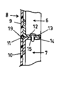
The sheet 8 compri~es two portions 9 and 10 with a
Vee notch 11 (see Fig.3) across the sheet 8 aligned
with and facing the lower and upper frame members 13
and 14 of the side portions 6 and 7 respectively. The
material 19 left as a result of the formation of the
notch 11 acts as a hinge allowing the part 6 of the
side 7 to hinge down inwardly relative to the side part
7. Securement means to be described releasably secures
the side part 7 to the sides 2 and 4 when the side part
7 is in the upright operational position shown in
Fig.l.
The material from which the liner panel is made is
such that it will withstand multiple flexures at the
hinge 19 without fracture, high density polypropylene
is a suitable material for this purpose.
The internal pressure when a liner bag in the
container is filled with liquid could, in the absence
of load resisting means, apply unacceptable loads on
the hinge 19 of the sheet 8. In Figs.3 and 4 the load
20 resisting means comprises pins 12 fixed to the bottom
rail 13 of the part 6 of the side 1 and holes lS in the
upper rail 14 of the part 7 of the side 1. It is to
be understood that the arrangement could be reversed
f with the pins in the rail member 14 and the holes in
the member 13. In another arrangement pins and holes
could be provided on both rail 13 and rail 14.
Location means is provided the prevent outward

wo~7 ~A21~2892 ~ u~
movement of the upper end of the part 6 of the side 1
beyond the upright condition shown in Fig.l. The
location means comprises hook lugs 16 spaced from the
inner surface of the liner sheet 21 on the sides 2 and
4. The end members 17 of the frame of the part 6 are
engaged by the hook lugs 16. The lugs limit the
outward movement of the part 6 and at the same time
prevent the spreading apart of the sides 2 and 4.
Latching means in the form of slide bolts
0 identified 20 on the part 6 are engagable in holes 22
in the sides 2 and 4 to retain part 6 in the Fig.l
condition.
In the ~econd embodiment of the invention the part
6 of the side 1 is able to be hinged outwardly. This
can be best seen in Fig.5 where the portions 6 and 7 of
the sheet 8 are separate members and are not hinged
together as in the first embodiment. The angle shaped
rails 13 and 14 are replaced by rectangular tubular
members 23 and 24 and a strip of high density
polypropylene or like performance material is fixed to
the members 23 and 24 as illustrated and indicated 26
to act as a hinge. It is to be noted that in this
arrangement the Vee form of the notch of Figs.3 and 4
has been varied to a groove of U form.
Load resisting means comprising pins and holes as
used in the first embodiment can also be used in this
embodiment, ~ee Figs.5 and 6. Again, it is to be

W09~ 7 ` ~ 1g ~ rcTlAu~w&~
-- 7 --
understood that the arrangement could be reversed with
the pins 12 in the member 24 and the holes 15 in the
member 23. In another arrangement pins and holes could
- be provided on both members 23 and 24.
Figs.7 and 8 illustrate an alternative load
resisting means. As illustrated there is a load lug
27, which can be a single central broad lug or as an
alternative two or three narrow lugs spaced along the
length of the member 24, where the lug 27 extends above
the top of the member 27. The lug 27 is accommodated
in a very wide channel 28 in the hinge strip 26. As
shown in Fig.7, the part 29 of the lug 27 extending
above the member 24 laterally supports the bar 23
against loads exerted in the direction of the arrow 'L
by the contents of the container of which the side l
forms part. As shown in Fig.8 hinging of the part 6 of
the side l relative to the part 7 will automatically
disengage the lug part 29 from the member 23.
Location means for the part 6 in this embodiment of
the invention comprise lugs 25 on the part 6 which will
bear on the outer end edges of the sides 2 and 4. The
lugs 25 may include hooked ends to engage the outer
faces of the sides 2 and 4 adjacent the side l thereby
providing a restraint against the separation of the
upper edges of the sides 2 and 4 adjacent the side l.
Latching means in the form of slide bolts as used
in the first embodiment would be suitable. As the

W09~ 7 C A 2 1 8 2 8 9 2 PCT/AU~W~
-- 8
static presæure exerted by the liquid in a liner bag in
the container will be low at the upper end of the part
6 the slide bolt latching meanæ will adequately resist
the applied pressure. The static pressure exerted at
the upper zones of the sides 1 to 4 will also be
resisted by an appropriately designed lid which will
embrace the upper edges of the sides 1 to 4 and is
almost invariably used with liquid carrying containers
of the present type.

Dessin représentatif
Une figure unique qui représente un dessin illustrant l'invention.
États administratifs

2024-08-01 : Dans le cadre de la transition vers les Brevets de nouvelle génération (BNG), la base de données sur les brevets canadiens (BDBC) contient désormais un Historique d'événement plus détaillé, qui reproduit le Journal des événements de notre nouvelle solution interne.

Veuillez noter que les événements débutant par « Inactive : » se réfèrent à des événements qui ne sont plus utilisés dans notre nouvelle solution interne.

Pour une meilleure compréhension de l'état de la demande ou brevet qui figure sur cette page, la rubrique Mise en garde , et les descriptions de Brevet , Historique d'événement , Taxes périodiques et Historique des paiements devraient être consultées.

Historique d'événement

Description Date
Inactive : CIB de MCD 2006-03-12
Le délai pour l'annulation est expiré 1999-12-13
Demande non rétablie avant l'échéance 1999-12-13
Réputée abandonnée - omission de répondre à un avis sur les taxes pour le maintien en état 1998-12-14
Demande publiée (accessible au public) 1996-06-20

Historique d'abandonnement

Date d'abandonnement Raison Date de rétablissement
1998-12-14

Taxes périodiques

Le dernier paiement a été reçu le 1997-11-28

Avis : Si le paiement en totalité n'a pas été reçu au plus tard à la date indiquée, une taxe supplémentaire peut être imposée, soit une des taxes suivantes :

  • taxe de rétablissement ;
  • taxe pour paiement en souffrance ; ou
  • taxe additionnelle pour le renversement d'une péremption réputée.

Veuillez vous référer à la page web des taxes sur les brevets de l'OPIC pour voir tous les montants actuels des taxes.

Historique des taxes

Type de taxes Anniversaire Échéance Date payée
TM (demande, 2e anniv.) - petite 02 1997-12-15 1997-11-28
Titulaires au dossier

Les titulaires actuels et antérieures au dossier sont affichés en ordre alphabétique.

Titulaires actuels au dossier
LADISLAV STEPHAN KARPISEK
Titulaires antérieures au dossier
S.O.
Les propriétaires antérieurs qui ne figurent pas dans la liste des « Propriétaires au dossier » apparaîtront dans d'autres documents au dossier.
Documents

Pour visionner les fichiers sélectionnés, entrer le code reCAPTCHA :


Pour visualiser une image, cliquer sur un lien dans la colonne description du document. Pour télécharger l'image (les images), cliquer l'une ou plusieurs cases à cocher dans la première colonne et ensuite cliquer sur le bouton "Télécharger sélection en format PDF (archive Zip)" ou le bouton "Télécharger sélection (en un fichier PDF fusionné)".

Liste des documents de brevet publiés et non publiés sur la BDBC .

Si vous avez des difficultés à accéder au contenu, veuillez communiquer avec le Centre de services à la clientèle au 1-866-997-1936, ou envoyer un courriel au Centre de service à la clientèle de l'OPIC.


Description du
Document 
Date
(aaaa-mm-jj) 
Nombre de pages   Taille de l'image (Ko) 
Abrégé 1996-06-20 1 38
Description 1996-06-20 8 251
Page couverture 1996-11-22 1 14
Revendications 1996-06-20 4 131
Dessins 1996-06-20 3 57
Dessin représentatif 1997-09-16 1 4
Rappel de taxe de maintien due 1997-08-14 1 111
Courtoisie - Lettre d'abandon (taxe de maintien en état) 1999-01-11 1 184
Rapport d'examen préliminaire international 1996-08-07 3 47