Note : Les descriptions sont présentées dans la langue officielle dans laquelle elles ont été soumises.
21 8301 3
rODD . P0023
ANTI-TEIEFT ALARM FOR ELECTRICALLY OPERATED DEVIC~S
Field of the Invention
The present invention relates to 2n anti-theft
5 device for devices powered by external electrical power
sources. It is particularly useful for the protection
of computers, televisions, VC~ s and the like which are
ea s i ly portab 1 e .
I~ack~round to the Invention
In the past fe~ years computers have become
commonplace in commerce, in industry and in ;;he home.
As the amount of slorage and com~uting capac t- goes up,
the more valuable are the computers, their component
parts, the soft-.vare stored on them and the i!l~ormation
15 contained on disk, tape or optical storage de~/ ces. __
While original equipment manufacturers and 30~t-~are
manufacturers have concentrated on developing password
systems and other security devices to preven~
unauthorized access to information on the computer, ver-
20 little has been done to physically protect ti1e computers
themselves. This is surprising, given the ~act that
computers are getting smaller and therefore :~ore easily
stolen, or the fact that computers are becomillc; more
modularized, with important component parts ~Jhich are
25 very easily and quickly removed from computers. Even
physical protection has been limited, e.g. to cable
restraints which are attached to the outer case of a
computer and an immobile ob~ect such as a desk.
Although large numbers of thefts of computers and
30 components are reported to police and compan~ security
personnel, there is little chance of recover~. It is
costly to replace stolen computers. Perhaps more
importantly though, considerable loss of time and
resources occurs as a result of having to reconstitute
35 lost information. This is particularly so for small
businesses and home businesses, ~hich rely he~v~ ly on
computerized information and transactions . ,~-~ 50, all
information stored in memory, e.g. on hard disk is also
stolen, thus compromising security of information.
. ~ 2~83013
-- 2 --
Preventing theft Qf computers and their component parts
such as disk drives, memory chips, CPUs, expansion cards
and the like is very important for businesses; and
increasingly for home computer users. In high traffic
5 area such as hospitals, and in poorly guarded areas
(most small businesses ) computers are easily .argetted
and stolen.
Attempts have been made in the past to provide
anti-theft devices for televisions, computers and the
10 like. For example, ù . S . Patent ' gO8 608 .vhlch issued
March 13, 1990 discloses electrical equipmenl~ with a
security device which is controlled by a mi~ roprocessor.
The microprocessor produces a ATarning from a warning
device when the electrical power is lost and/~r the
15 equipment is moveà. The device has an inter~ace which
requires a password and which also allows ba~tery
checks, alarm tests and alarm arming sequences to be
passed between the equipment and the securit-,~ device.
The security device is mounted inside the computer, with
20 the circuitry on a card installed in a so-ca~Led
expansion slot in the computer. U.S. Patent ~ 317 304
hich issued May 31, 199~ to A. Choi shows a battery-
operated device which is used to trigger an a' arm. The
battery may be recharged. There may be an anti-tamper
25 switch which senses when the device ' s housing is being
removed. The alarm must be programmed for delay before
triggering, and for loudness and duration. ~ has a
disarming key. The device may be external to a computer
or internal, mounted in an ex~oansion slot. - ~he device
30 requires a key pad which is used to set ~arious control
parameters, such as alarm loudness, and provides a
password protection and alarm disarming ~unction . U. S.
Patent 4 586 514 which issued August 11, 1987 discloses
an electrically operated alarm which has a motion
35 sensing switch, and an anti-tamper s~-~itch to detect ~ _
opening of a computer case. None of the alarms are
entirely satisfactory. The present invention is
2183013
-- 3 --
intended to provide an improved alarm for electrically
operated devices.
Summary of th~ Invention
Accordingly the present invention provides an anti-
5 theft alarm for an e:~ternally powered electricallyoperated device, said device having a case containing
internal components, said alarm comprising:
a) a rechargeable battery;
b) input sensing means comprising a motion sensor to
10 detect movement of the device, and a tamper switch to
determine if the case is about to be opened ~r has been
opened;
c ) a DC power supply connected to a circuit Eor
recharging the battery, said DC supply being dependent
15 on the external power supply for the device;
d) a warning means activated by controller means,
powered by the battery, said controller means being
activated by a condition selected from ~he group
consisting of i) no DC power and activation oE the
20 motion sensor and ii) activation of the tamper switch;
e) an arming latch which keeps the warning .~eans
activated when either of the conditions in d ! is
satisfied;
e) a key switch which in a first position is able to
25 disarm the alarm when the DC power is off and in a
second position is able to arm the alarm.
The alarm may be an analogue device or a digital
device .
In another embodiment at least the tam~er switch
30 and key switch are is contained in a housing which has a
base and a cover selected from the group consisting of
a) said base being attachable to the case for the
electrically operated device, said key switch being
attached to the cover and said key switch and base
35 having means such that, when the key switch is locked,
the cover cannot be removed from the base and, when the
key switch is unlocked, the cover is detachable from the
21830~3
-- 4 --
base and b) said base being attachable to the case for = ~
the electrical ly operated device, said key switch being -
attached to the base and said key switch and cover
having means such that, when the key switch i~ locked,
5 the cover cannot be removed from the base and, when the
key switch is unlocked, the cover is detachable from the
bas e .
In a further embodiment the tamper switc~l comprises
a cooperating post and hinge lever switch.
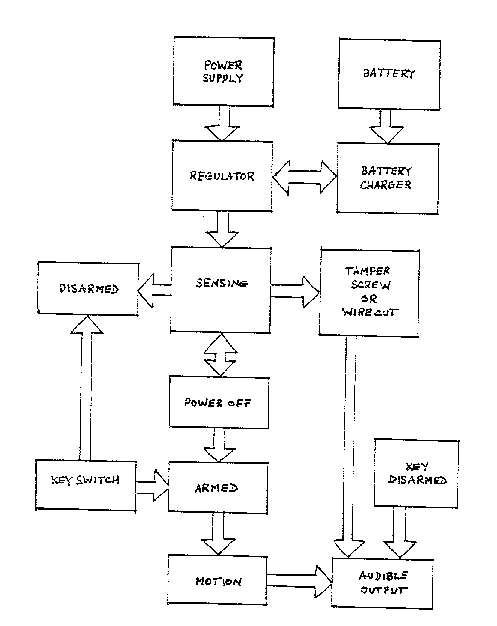
10 DescriDtion of the Drawinqs _ _
Figure 1 is a block diagram show~ ng the various
functions in one embodiment of the anti-thef . alarm.
Figure 2 shows an electrical circuit di~gram of
another embodiment of the anti-theft alarm.
15Figure 3 is the same as Figure 2 except rhat it
overlays the functiQns of portions of the circuitry.
Figures 4a a~d 4b, when combined, comprise a
circuit diagram for an embodiment of an anti-theft alarm :~
operated with a computerized chip.
20Figure 5 is an exploded view of a lock and
associated cover ~qith some electronic components
therein, and a base of an emoodiment of an ant -theft
alarm .
Figures 5a and 5b show an inside of the base and a
25 plate for a lock, respectively, used in Figure 5.
Figure 6 is a view of an anti-theft alarm of the
present invention installed on a computer case
(partially shown).
Detailed DescriPtion of Preferred Embodiments
Figure 1 is a block diagram which shows the DC
power supply feeding through a regulator to a battery
charger and to the rest of the alarm circuitry through
the sensing device. ~he sensing device may be a mercury
switch or other motion detecting device. The preferred
35 motion detector is a piezoelectric sensor or tip switch.
If the power is off then the alarm is armed If the
moticn sensor then detects motion, an audible alarm is
~ 2183013
-- 5
set off.
In the event that the tamper device, e . g tamper
screw, membrane switch, hinge lever switch, is
activated, then the audible alarm is set off, .~rhether
5 the power is connected or not. The audible alarm or the
motion sensor can be disarmed by means of a :Yey switch.
Figures 2 and 3 show an alarm which has a speaker S
associated therewith. Computers, televisions VCRs and
the like are senerally operated using ~ains AC current
10 and may have stepped down voltages and power supply
available. Computers most often have a
rectifier/transformer for the provision of 1 ~ vDC, for :
operation of the components within. This DC source may
be used with the present invention. The function of the
15 DC source inasfar as the alarm is concerned i, two-fold.
The first is to provide a means for recharging battery
B. The second is to provide a means of telilng whether
the AC power is connected to the computer. If the AC
power is cut off, either by unplugging the AC power
20 cord, cutting the power cord or shutting off the AC
power, then there is no DC power. ::
When there is DC power available it is possible to
activate motion sensor M without the arming :atch and
thus the alarm being activated. When there i~ no
25 external power to the present alarm, the battery is the
sole electrical source. In this condition, i.- the
motion sensor M is tipped and thus activated, the arming
latch ensures that power is continuously sen~ to the
speaker or buzzer S. If the AC power is turned back on,
30 then the alarm returns to its quiescent state.
Pref erably the alarm has circuitry or switching
which permits modifying the volume of the alarm and the
time it takes between activation of the motion sensor
and activation of the speaker or buzzer. For example in
35 a hospital environment it may be desirable to give an
early warning of activation of the alarm, in -he event
that the alarm is accidentally triggered. This may be
2183013
-- 6 --
accomplished by giving a 30, 60 or 120 second delay
before the alarm i9 set off. In addition, or
alternatively, the alarm may be set off at low volume to
begin with, but after a short time, e.g. 30 or 60 F
5 seconds the alarm is set off at full volume. Such
conditions may be pre-set in the factory, may be
settable on site by means of switches or other means.
Suitable means for controlling the time de l ay~ include
capacitors and programmable interrupter circllits (PICs).
If the tamper switch ~ is activated, chen the
arming latch ensures that power is continuous ly sent to
the speaker or buzzer S, whether the DC power is on or
off. This prevents a thief from opening the ~ase and
removing valuable components ~rom therein vithout having
15 to take the T.vhole computer. The tamper switch may be an
on-off switch which is controlled by the distance that a
case-holding screw is screwed into the case, e.g when
the screw is fully screwed in, the circuit is open and
when the screw is removed or not fully screwed in the
20 circuit is closed. Other types of tamper sw tch include
membrane switches and hinge lever subminiatur~ switches . :
Figures 4a and 4b show another, preferred circuit
diagram for a digitally-operated anti-theft alarm, which
acts similarly to that shown in Figures 2 and 3.
Of course, legitimate movement of the computer is
desirable, as is legitimate removal of the case, for
example for reasons of maintenance and upgrading. A key
lock is provided to electrically disarm the alarm.
In one embodiment the key lock may per~orm both an
30 electrical or electronic function to disarm -he alarm
and also a mechanical function with respect to the
tamper switch. With respect to the tamper switch, the
key lock preferably is located in a box, comprising a
base and a cover, which is attached to the outside of
3S the computer case~
The box covers may cover the tamper device, e . g .
motion detector. Preferably, however, the tamper device
2~301~
-- 7
is located inside the electrically operated device, e . g.
a computer, primarily because there is usualiy plenty of
room to house the tamper device. In addition in the
case of a motion detector, the spacial alignmen~ is
5 important ~nd the detector cannot be mounted on its
s ide .
The prefer}ed box is sho~ . in Figure 5. ~he base
for the box is better explained hy reference to Figure
5a. The box comprises a base ll and a cover l 2 . In the
lO embodiment shown ~he cover is in two pieces, ~ . e . plate
13 in which key lock 14 is mounted, and shroud 15 .
Shroud 15 has two side walls 16 and 17, an end wall 18,
and end posts 35 at the end of cover opposite ~o end
wall 18. The bo~toms of walls 16 and 17 have ~lared
15 skirts 19 and 20 respectively. Base ll has a bottom 21
and inwardly flared walls 22 and 23, and end ~all 24
attached thereto. Base also has a post 25, ~ raised
stop 26 and a plurality of screw apertures 39. Plate 13 ==
has a tongue 27 which is adapted to fit into slot 28 in
shroud 15. End wall 18 has a cut-out 29 for passage oi
a cable. Rey lock 14 has a bod~ 30 and a plate 31 which
is rotatable by means of a key 32. Plate 31 has tongues
33 and 34 on opposite sides of the axis of rotation of
the plate 31.
Located inside the box, e.g. in shroud ' 5 are some
electronic and mechanical components of the alarm.
Components that are pref erably not housed in the box
include a DC power supply, a rechargeable battery and a
motion sensor, all of which are accommodated _n the case
30 of the electrically powered device, e.g. computer case.
Aa shown in Figure 5, certain electronic components are
situated within component 36. Attached to component 36
is a hinge lever subminiature switch 37, which is part
of the tamper switch, and sprung on-off trigger switch
35 38, which is part of the key switch.
With reference to Figure 6, the box 40 is attached
to computer case 41 which comprises a back 42 and cover
,
2183013
.
-- 8
43. In the embodiment shown it is usual for the base 11
of box 40 to sit on an 1-bracket 49. Cover 43 is
attached to back 42 with screws 4g, 45 and o~her screws
not shown. Back 42 has a number of so-cal' ed expansion
5 slots 46 therein. The electronic components :n box 40
are connected by a cable 48 to the DC power 3upply,
rechargeable battery, motion sensor and other components
which are inside computer case 41.
In preparation for assembly, and in operat~on,
10 plate 13, with attached lock 14, is situated !n shroud
15, so that tongue 27 fits into slot 28 and plate 13 is
firmly held in place with end pos~s 35. Just prior to
assembly, plate 31 is in the position shown i !l Figure 5
so that the alarm is unarmed, i . e. trigger switch 38 is
15 open. Plate 13 is removable so that in the event that
key 32 is lost, the ~hole of the loc~ assembly can be
replaced quickly rather than having to wait ror new keys
to be cut. High security locks are ,oreferable in order
to minimize the risk that the lock can be picked and the
20 alarm disarmed.
When installing the alarm, items inside ~he
comDuter case are first instaLled. The connector cable
48 is led outside the computer case. L-bracket 49 is
affixed to the computer cover 43, preferably ~;~ith a
25 strong adhesive. Base 11 is affixed to L-bracket 49,
preferably with a strong adhesive. Cover 43 ~ s then
placed on the computer back 42 and the computer back
affixed thereto, using mounting screws. I~ne of the
screws, 44, passes through one of the screw apertures 39
3~ in base 11, thus assuring that the base, and therefore
the computer cover 43, cannot easily be remo~7ed from the
computer back without damaging the base 11. It should
be noted that screw 44 will be inaccessible ~hen shroud
15 is attached to base 11, and therefore screw 44 cannot
35 be removed without first removing shroud 15.
The skirts 19 and 20 of shroud 15 are then slid
inside walls 22 and 23 respectively of base 11, until
~ 2183013
_ 9 _
end wall 18 touches wall 24. In practice, cable 48 i5
trapped between walls 18 and 24, and passes through cut-
out 29 in end wall 18. As shroud 15 is slid into place
on base 11, a lever on hinge lever subminiature switch
5 37 touches post 26 on base li and is depressed, thus
arming the tamper switch. Plate 31 of the lock is
rotated with key 32 in the direction of arrow ~ in
Figure 5, so that tongue 33 depresses the spr ng on
switch 38, thus arming the alarm. At the same time,
10 tongue 34 moves behind stop 25 on base 11 so ~hat the
shroud 15 may not be removed rom base 11 .~ithout first
unlocking the lock 14 with key 32. The alarm is then
armed .
Base 11 and the shroud 15 are stamped ~rom metal
15 sheet. However, they may be made of reasonabl~ rigid
synthetic plastic material.
In operation, in the event that someone attempts to
cut cable 48 or apply brute force to lever box 40 off,
the alarm will be immediately set off, and the only way
20 to stop the alarm is to unlock the lock 14 ~qith a key,
and thus open switch 38. In the event that the AC power
cable is unplugged and the computer moved ~ithout first
unlocking lock 14, the motion sensor (not shown) will
detect movement and trigger the alarm. As indicated
25 hereinbefore, there may be a delay or the alarm may be
at a low level for a few seco~ds in the evenl that the
movement was unintentional. If no action is taken to
unarm the alarm, the alarm ~ill sound.
In order to insert new components in the computer,
30 it is first necessary to disarm the alarm by unlocking
the ke~ switch . ~he shroud 15 is then removed f rom base
11 and screw 44 removed, together with other screws such
as 45 which hold cover 43 in place. ~he cover 43 ca~
then be removed, revealing the inside of the computer.
As is known, computers are often associated with
peripherals such as printers, scanners, monitors, CD
storage devices, tape and other storage devices, modems
2 ~ 830 1 ~
-- 1 o
and the like, none of which generally ha~e a convenient
~C power source for use with the alarm of the present
invention. Also in the typical office there is
equipment such as fax machines, which also do not
S usually have convenient DC power sources. These
peripherals and other devices can be protected by
connecting them to an alarm of the present invention
which is encased in the body of a computer. Each
peripheral may be connected with wire which _f cut or
iO removed triggers the alarm immediately. Alternatively
the peripheral device may detect separation ~rom the
computer and an alarm is triggered.
A single user of a computer would usual'~/ prefer to
have the audible alarm built into the anti-theft device.
1- Companies and institutions with large numbers of
computers may prefer not to have an audible alarm at
each individual computer, but would prefer to have the
alarm condition show up in a central location, e.g
security office. In such cases, instead of tlle audible
~0 alarm circuitry, the alarm condition may be transferred
to the central location by telephone line or network.
In one embodiment of the invention the alarm design
allows for electrical signals to be passed to other
computer components and to accept electrical signals
from other components. In this way alarm status may be
communicated and arming, disarming and alarm Functions
may be triggered remotely.
An anti-theft device of the present invention was
constructed using the circuit diagram of Figure 2 and
_0 installed on a computer. All of the resistors were 0.25
watt, of the values shown in Figure 2. All unmarked
diodes were lN4148. Integrated circuits IC1 an IC2 were
CD4069 and transistors Q1 to Q4 were 2N4401. A second
anti-theft device of the present invention wa~
_5 constructed using the diagram of Figure 4. The alarms
so-constructed operated and activated substantially as
described above.