Sélection de la langue

Search

Sommaire du brevet 2183061 

Énoncé de désistement de responsabilité concernant l'information provenant de tiers

Une partie des informations de ce site Web a été fournie par des sources externes. Le gouvernement du Canada n'assume aucune responsabilité concernant la précision, l'actualité ou la fiabilité des informations fournies par les sources externes. Les utilisateurs qui désirent employer cette information devraient consulter directement la source des informations. Le contenu fourni par les sources externes n'est pas assujetti aux exigences sur les langues officielles, la protection des renseignements personnels et l'accessibilité.

Disponibilité de l'Abrégé et des Revendications

L'apparition de différences dans le texte et l'image des Revendications et de l'Abrégé dépend du moment auquel le document est publié. Les textes des Revendications et de l'Abrégé sont affichés :

  • lorsque la demande peut être examinée par le public;
  • lorsque le brevet est émis (délivrance).
(12) Demande de brevet: (11) CA 2183061
(54) Titre français: ELEMENT CHAUFFANT PAR INDUCTION
(54) Titre anglais: INDUCTION HEATING ELEMENT
Statut: Réputée abandonnée et au-delà du délai pour le rétablissement - en attente de la réponse à l’avis de communication rejetée
Données bibliographiques
(51) Classification internationale des brevets (CIB):
  • H05B 6/12 (2006.01)
  • H05B 6/06 (2006.01)
(72) Inventeurs :
  • SNOWBALL, MALCOLM ROBERT (Royaume-Uni)
(73) Titulaires :
  • INDUCED ENERGY LIMITED
(71) Demandeurs :
  • INDUCED ENERGY LIMITED (Royaume-Uni)
(74) Agent: GOWLING WLG (CANADA) LLP
(74) Co-agent:
(45) Délivré:
(86) Date de dépôt PCT: 1995-02-09
(87) Mise à la disponibilité du public: 1995-08-17
Requête d'examen: 2002-01-10
Licence disponible: S.O.
Cédé au domaine public: S.O.
(25) Langue des documents déposés: Anglais

Traité de coopération en matière de brevets (PCT): Oui
(86) Numéro de la demande PCT: PCT/GB1995/000258
(87) Numéro de publication internationale PCT: WO 1995022239
(85) Entrée nationale: 1996-08-09

(30) Données de priorité de la demande:
Numéro de la demande Pays / territoire Date
9402495.7 (Royaume-Uni) 1994-02-09

Abrégés

Abrégé français

Un élément chauffant pour une plaque de cuisson à induction comprend un serpentin plat enroulé en spirale (30) consistant en une pluralité de conducteurs parallèles et isolés. Le serpentin est enroulé dans une rainure (32) en forme de spirale disposé à la surface supérieure d'une plaque de support en plastique (31). Une base circulaire (33) constituée en un matériau à haute perméabilité magnétique est disposée sur la face inférieure de la plaque de support (31). La base (31) focalise le champ magnétique généré par le serpentin dans une zone de chauffe au-dessus du serpentin, et empêche également toute partie métallique environnante de chauffer de manière indue.


Abrégé anglais


A heating element for an inductive cooking hob comprises a flat spirally-wound coil (30) consisting of a plurality of parallel insulated
conductors. The coil is wound in a spirally-extending groove (32) disposed on the upper surface of a plastics former (31). A circular base
(33) of highly magnetically permeable material is disposed on the underside of the former (31). The base (31) focuses the magnetic field
generated by the coil into a heating area above the coil, and also prevents any surrounding metalwork from inadvertently being heated.

Revendications

Note : Les revendications sont présentées dans la langue officielle dans laquelle elles ont été soumises.


Claims
1) An induction heating element comprising a flat
spirally-wound coil disposed on the upper surface of a flat
former and a base of magnetically permeable material disposed
on the under surface of the former.
2) An induction heating element as claimed in claim 1, in
which a groove is formed in the upper surface of the former for
receiving the spirally-wound coil.
3) An induction heating element as claimed in claims 1 or
2, in which the former comprises a plastics material.
4) An induction heating element as claimed in claim 3, in
which the plastics material has a high thermal conductivity.
5) An induction heating element as claimed in any
preceding claim, in which the coil comprises a plurality of
parallel-connected conductors.
6) An induction heating element as claimed in claim 5, in
which the conductors are insulated from each other.
7) An induction heating element as claimed in claims 5 or
6, in which the conductors are circular in section.
8) An induction heating element as claimed in claims 5 or
6, in which the conductors comprise strips of conductive
material .
9) An induction heating element as claimed in any
preceding claim in which the base is circular.

Description

Note : Les descriptions sont présentées dans la langue officielle dans laquelle elles ont été soumises.

~ WO95/22239 2 ~ 8 3 0 6 1 P~
Imluction /Ic~tin~ El~me~t
This invention relates to an induction heating element.
, Cooking hobs are known which comprise a large induction
heating coil, on which pans having a conductive base can be
stood. In use, a high LL~YU~ Y electrical signal (in excess
5 of 20 KElz) is applied to the coil, which generates a magnetic
f ield that induces secondary currents in the pan base . The
base of the pan is not an ideal conductor, thus as the current
f lows electrical energy is dissipated as heat in the base of
the pan. This type of heating is able to deliver up to 5KW of
10 heating power directly into the base of the pan. Thus, cooking
hobs of this type are extremely fa6t and efficient.
Generally the hob comprises a flat spirally wound coil
connected at its opposite ends to a high freguency current
supply. The magnetic field around the coil induces a current
15 in any conductive objects which come within the field. Thus,
the coil has to be spaced apart from metal components in the
housing of the hob, in order to avoid any undesirable heating
of these. The efficiency of space utilisation in induction
oooking hobs is theref ore poor, owing to the large space
20 isolation required around the coils,
Thus in accordance with this invention as seen from a
f irst aspect, there is provided an induction heating element
comprising a coil and an element of magnetically permeable
material disposed adjacent at least an external part of said
25 coil.
In use, the lines of magnetic flux around the coil flow
through the magnetically permeable element rather than through
the "uLL-)ullding casing of the hob, which is less permeable.
Preferably one side of the coil is exposed so that the
30 magnetic field is projected outwardly from that side to heat
conductive cooking utensils inductively coupled with the coil.
Preferably said magnetically permeable element
comprises a circular base on which the coil is mounted.
Additionally or instead, said permeable element encircles the
35 coil. The circular base shields any surrounding metalwork from
the magnetic field and also focuses th- field upwardly towards

WO 95122239 2 ~ 8 3 ~ 6 1 P~
2.
the heating area.
Preferably the coil is flat. Preferably the coil
comprises a 6pirally-wound conductor. The conductor is
preferably ~1; CpncDd on the surface of a flat former.
5 Preferably the former comprises a spirally-extending groove in
its upper surface for receiving the conductor.
Pref erably the f ormer comprises a plastics material,
preferably having a high thermal conductivity. The material
of the former enables any heat in the coil to be rapidly and
lO evenly transferred.
Pref erably the circular base is disposed on the
unders ide of the f ormer .
It will be appreciated that the former keeps the
surface of the coil flat. Uneven electromagnetic coupling with
15 the pan will occur if the surface of the coil is uneven, and
thus hot spots will occur owing to the uneven energy transfer.
A flat surface to the coil minimises hot spots, due to each
turn being exactly the same distance from the pan.
Pref erably the element comprises f errite material,
20 which raises the inductive reactance of the coil.
Induction heating coils are generally driven by a high-
frequency supply current. At these high frequencies current
tends to f low only in a thin layer adj acent the surf ace of the
conductor, rather than in its full cross sectional area. This
25 so-callea skin effect causes increased I2R losses, owing to the
increased current density flowing through the surface layer of
the conductor.
Thus, in accordance with this invention as seen from a
second aspect, there is provided an induction heating element
30 having a flat spirally-wound coil which comprises a plurality
of parallel connected conductors.
Thus, at high frequencies the skin effect is m;nim;c~l
by using a plurality of conductors to pass the current. The
combined surface area of these conductors is much greater than
35 the effective surface area of a conventional conductor, thus
the I2R losses are m;n;micc.~
Preferably the conductor comprises a plurality of
conductive strips or circular-section conductors connected in
~arallel. Preferably the conductors are insulated from each

2 ~ 8306 1
W095/22239 r~
other. Preferably the conductors form a winding, which is also
preferably insulated.
A large proportion of the supply current to inductive
cooking hobs is dissipated as heat in the centre of the coil.
5 It has been proposed to remove the centre of the coil in order
to alleviate this heating problem, however this leads to uneven
heating of the pan. We have now devised an induction heating
element which alleviates this problem.
In accordance with this invention as seen from a third
10 aspect, there is provided an induction heating element
comprising a flat spirally wound coil disposed around a core
of magnetically permeable material.
Thus, any uneven heating of the pan is avoided by
utilising a magnetically permeable core which directs the
15 magnetic field towards the centre of the coil. Heating of the
centre of the coil is alleviated since the centre has been
replaced by the magnetically permeable core. Preferably the
core comprises f errite .
Fmhorlir-nts of this invention will now be described by
20 way of examples only, and with reference to the ~-c nying
drawings, in which:
FIGURE 1 is a sectional view through an pmh~lir- -t of
induction heating element in accordance with this invention;
FIGURE 2 is a sectional view of the induction heating
25 element of Figure 1 showing the generated magnetic lines of
f lux; and
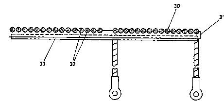
FIGURE 3 is a sectional view through a second
pmho~;r -nt of induction heating element in accordance with this
invention .
Referring to Figure 1 of the drawings, there is shown
an induction heating element comprising a flat spirally-wound
coil 10. The coil 10 is would around a central cylindrical
core 11 of highly magnetically permeable material such as
f errite .
The coil is mounted inside a housing 12 having a
circular base 13 and an upstanding peripheral wall 14. The
housing 13 i5 also formed from highly magnetically permeable
material such as ferrite, and the core 11 may be formed
integrally with its base 13.
_ .. _ . . . .... . . . . . . .

0 95/22239 2 1 8 3 0 6 1 1 J,.
4.
The coil 10 comprise6 a single winding of a rectangular
or square-section conductor 20. The conductor 20 comprises a
plurality of conductive strips 21 coated with an insulating
material (not shown), contained within an outer insulating
5 coating 22. Insulated supply t~rmin~l~ 23 are connected to
opposite ends of the conductor 20 and project through the base
of the housing 12.
In use, when a high frequency supply is connected
between the tPrm;n~l~ 23, the coil generates a magnetic field
10 as shown in Figure 2. The lines of magnetic flux extend
through the base 13 and peripheral wall 14 of the magnetically
permeable housing and through the core 11. The upper surface
of the heating element is open, and thus the lines of magnetic
flux extend upwardly into free space.
cnnr9llrtive cooking utensils placed on the upper surface
of the heating element inductively couple with the coil 10, and
secondary alternating currents are developed in the utensils.
These currents develop I~R losses owing to the resistance of
the material from which the utensil is formed: this generated
20 heat may be used for cooking.
Referring to Figure 3 of the drawings, there is shown
an alternative ~hQ-l i r -nt of induction heating element . The
heating element comprises a flat spirally-wound coil 30
disposed on a circular former 31 formed from a plastics
25 material having a high thermal conductivity. The former 31
comprises a spirally-extending groove 32 in its upper surface,
in which the conductor of the coil is wound.
A flat circular base 33 of a highly magnetically
p~ --hle material, such as ferrite, is recessed into the
30 underside of the former 31.
The coil 30 comprises a single circular-section winding
which consists of a plurality of circular-section conductors
coated with an insulating material. The winding is twisted
from end-to-end, such that each conductor extends in a helical
35 fashion. This arrangement gives a shallow coil which is less
susceptible to skin effects, and thus runs at a lower
temperature than conventional coils.
The coil winding is sufficiently flexible to enable the
coil to be wound almost to the centre, so that uneven heating

~ W0 9Y22239 2 1 ~ 3 0 6 1 1~1~. -
o~ the pan is avoided.

Dessin représentatif
Une figure unique qui représente un dessin illustrant l'invention.
États administratifs

2024-08-01 : Dans le cadre de la transition vers les Brevets de nouvelle génération (BNG), la base de données sur les brevets canadiens (BDBC) contient désormais un Historique d'événement plus détaillé, qui reproduit le Journal des événements de notre nouvelle solution interne.

Veuillez noter que les événements débutant par « Inactive : » se réfèrent à des événements qui ne sont plus utilisés dans notre nouvelle solution interne.

Pour une meilleure compréhension de l'état de la demande ou brevet qui figure sur cette page, la rubrique Mise en garde , et les descriptions de Brevet , Historique d'événement , Taxes périodiques et Historique des paiements devraient être consultées.

Historique d'événement

Description Date
Inactive : CIB de MCD 2006-03-12
Demande non rétablie avant l'échéance 2004-02-09
Le délai pour l'annulation est expiré 2004-02-09
Réputée abandonnée - omission de répondre à un avis sur les taxes pour le maintien en état 2003-02-10
Lettre envoyée 2002-03-14
Inactive : Dem. traitée sur TS dès date d'ent. journal 2002-03-14
Inactive : Renseign. sur l'état - Complets dès date d'ent. journ. 2002-03-14
Exigences pour une requête d'examen - jugée conforme 2002-01-10
Toutes les exigences pour l'examen - jugée conforme 2002-01-10
Demande publiée (accessible au public) 1995-08-17

Historique d'abandonnement

Date d'abandonnement Raison Date de rétablissement
2003-02-10

Taxes périodiques

Le dernier paiement a été reçu le 2002-01-04

Avis : Si le paiement en totalité n'a pas été reçu au plus tard à la date indiquée, une taxe supplémentaire peut être imposée, soit une des taxes suivantes :

  • taxe de rétablissement ;
  • taxe pour paiement en souffrance ; ou
  • taxe additionnelle pour le renversement d'une péremption réputée.

Veuillez vous référer à la page web des taxes sur les brevets de l'OPIC pour voir tous les montants actuels des taxes.

Historique des taxes

Type de taxes Anniversaire Échéance Date payée
TM (demande, 3e anniv.) - petite 03 1998-02-09 1998-01-16
TM (demande, 4e anniv.) - petite 04 1999-02-09 1999-02-03
TM (demande, 5e anniv.) - petite 05 2000-02-09 2000-01-06
TM (demande, 6e anniv.) - petite 06 2001-02-09 2001-01-11
TM (demande, 7e anniv.) - petite 07 2002-02-11 2002-01-04
Requête d'examen - petite 2002-01-10
Titulaires au dossier

Les titulaires actuels et antérieures au dossier sont affichés en ordre alphabétique.

Titulaires actuels au dossier
INDUCED ENERGY LIMITED
Titulaires antérieures au dossier
MALCOLM ROBERT SNOWBALL
Les propriétaires antérieurs qui ne figurent pas dans la liste des « Propriétaires au dossier » apparaîtront dans d'autres documents au dossier.
Documents

Pour visionner les fichiers sélectionnés, entrer le code reCAPTCHA :


Pour visualiser une image, cliquer sur un lien dans la colonne description du document. Pour télécharger l'image (les images), cliquer l'une ou plusieurs cases à cocher dans la première colonne et ensuite cliquer sur le bouton "Télécharger sélection en format PDF (archive Zip)" ou le bouton "Télécharger sélection (en un fichier PDF fusionné)".

Liste des documents de brevet publiés et non publiés sur la BDBC .

Si vous avez des difficultés à accéder au contenu, veuillez communiquer avec le Centre de services à la clientèle au 1-866-997-1936, ou envoyer un courriel au Centre de service à la clientèle de l'OPIC.


Description du
Document 
Date
(aaaa-mm-jj) 
Nombre de pages   Taille de l'image (Ko) 
Dessin représentatif 1997-09-17 1 6
Abrégé 1995-02-09 1 49
Page couverture 1995-02-09 1 14
Description 1995-02-09 5 203
Revendications 1995-02-09 1 30
Dessins 1995-02-09 3 51
Revendications 2002-04-10 1 35
Rappel - requête d'examen 2001-10-10 1 129
Accusé de réception de la requête d'examen 2002-03-14 1 180
Courtoisie - Lettre d'abandon (taxe de maintien en état) 2003-03-10 1 179
PCT 1996-08-09 11 416
Correspondance 1996-08-09 1 57
Taxes 1998-01-16 1 43
Taxes 2002-01-04 1 30
Taxes 1999-02-03 1 44
Taxes 2000-01-06 1 38
Taxes 2001-01-11 1 31
Taxes 1997-02-07 1 48