Sélection de la langue

Search

Sommaire du brevet 2183405 

Énoncé de désistement de responsabilité concernant l'information provenant de tiers

Une partie des informations de ce site Web a été fournie par des sources externes. Le gouvernement du Canada n'assume aucune responsabilité concernant la précision, l'actualité ou la fiabilité des informations fournies par les sources externes. Les utilisateurs qui désirent employer cette information devraient consulter directement la source des informations. Le contenu fourni par les sources externes n'est pas assujetti aux exigences sur les langues officielles, la protection des renseignements personnels et l'accessibilité.

Disponibilité de l'Abrégé et des Revendications

L'apparition de différences dans le texte et l'image des Revendications et de l'Abrégé dépend du moment auquel le document est publié. Les textes des Revendications et de l'Abrégé sont affichés :

  • lorsque la demande peut être examinée par le public;
  • lorsque le brevet est émis (délivrance).
(12) Demande de brevet: (11) CA 2183405
(54) Titre français: PROCEDE ET DISPOSITIF D'ETANCHEIFICATION A L'EAU DES BORDURES D'EBAUCHES
(54) Titre anglais: METHOD AND APPARATUS FOR WATER-PROOFING EDGES OF BLANKS
Statut: Réputée abandonnée et au-delà du délai pour le rétablissement - en attente de la réponse à l’avis de communication rejetée
Données bibliographiques
(51) Classification internationale des brevets (CIB):
  • B31F 7/00 (2006.01)
  • B29C 65/00 (2006.01)
(72) Inventeurs :
  • SAGVIK, RAGNAR HARALD (Norvège)
  • LYNGAAS, LARS (Norvège)
(73) Titulaires :
  • ELOPAK SYSTEMS AG
(71) Demandeurs :
  • ELOPAK SYSTEMS AG (Suisse)
(74) Agent: NORMAN M. CAMERONCAMERON, NORMAN M.
(74) Co-agent:
(45) Délivré:
(86) Date de dépôt PCT: 1995-02-21
(87) Mise à la disponibilité du public: 1995-08-31
Licence disponible: S.O.
Cédé au domaine public: S.O.
(25) Langue des documents déposés: Anglais

Traité de coopération en matière de brevets (PCT): Oui
(86) Numéro de la demande PCT: PCT/IB1995/000113
(87) Numéro de publication internationale PCT: WO 1995023061
(85) Entrée nationale: 1996-08-15

(30) Données de priorité de la demande:
Numéro de la demande Pays / territoire Date
9403476.6 (Royaume-Uni) 1994-02-23

Abrégés

Abrégé français

Un procédé de drayage consiste à réaliser par calandrage, le long de la zone de bordure d'une ébauche d'emballage (1-3) constituée d'une couche (1) absorbant les liquides en sandwich entre au moins deux couches (2, 3) constituant une barrière à liquide, une languette (8), une encoche (6) à l'intérieur de la languette (8), un talon (9) à l'intérieur de l'encoche (6) et une rainure (7) à l'intérieur du talon. Le procédé consiste ensuite à replier la zone de bordure pour introduire la languette (8) dans la rainure (7), et à étanchéifier la zone de bordure contre le restant du matériau en feuille, de préférence uniquement par pression mécanique.


Abrégé anglais


A skiving method comprises forming by
milling, along an edge zone of a packaging blank
(1-3) comprised of a liquid-absorbent layer (1)
and at least two liquid-barrier layers (2 and 3)
thereon, a tongue (8), a recess (6) inwardly of
the tongue (8), a land (9) inwardly of the recess
(6), and a groove (7) inwardly of the land (9),
folding over the edge zone to insert the tongue
(8) into the groove (7). and sealing the edge zone
to the remainder of the sheet material, preferably
by mechanical pressure alone.

Revendications

Note : Les revendications sont présentées dans la langue officielle dans laquelle elles ont été soumises.


CLAIMS
1. A hemming method comprising forming, so as to extend
along a free edge zone of sheet material comprised of a
fluid-absorbent layer (1) and a fluid-barrier layer (3)
thereon, a tongue (8) upstanding substantially
perpendicularly to a plane of said sheet material, a recess
(6) inwardly of said tongue (8), a land (9) inwardly of said
recess (6), and a groove (7) inwardly of said land (9),
folding-over said edge zone, inserting said tongue (8) in
said groove (7) and sealing said edge zone to the remainder
of the sheet material.
2. A method according to claim 1, and further comprising,
a prior to the folding-over of said edge zone, forming,
along said edge zone, a cut-away (5) outwardly of said
tongue (8) and extending to the outer edge (4) of said edge
zone.
3. A method according to claim 1 or 2, wherein said tongue
(8), said recess (6), said land (9), and said groove (7)
(and said cut-away (5) if provided) are substantially
rectangular.
4. A method according to any preceding claim, wherein said
recess (6) is of a width slightly greater than the sum of
the height and the width of the land (9).
5. A method according to any preceding claim, wherein the
width of the tongue (8) is slightly less than that of the
groove (7).
6. A method according to any preceding claim, wherein, in
forming said recess (6) and said groove (7) (and said cut-
away (5) if provided), sections of said fluid-absorbent
layer (1) are removed to substantially a hidden surface (10)
of the fluid-barrier layer (3).
7. A method according to claim 6, wherein said sheet
material includes a second fluid-barrier layer (2), with the
fluid-absorbent layer (1) being disposed between the first-
mentioned and the second fluid-barrier layers (3,2),
sections of said second fluid-barrier layer (2) being
removed in forming said recess (6) and said groove (7) (and
said cut-away (5) if provided).

8. A method according to claim 7, wherein, in the sealing
of said edge zone to the remainder of the sheet material,
the portion of the first-mentioned fluid-barrier layer (3)
between the tongue (8) and the land (9) is sealed to the
portion of the second fluid-barrier layer (2) included in
the land (9).
9. A method according to claim 7 or 8, wherein, in the
sealing of said edge zone to the remainder of the sheet
material, the substantially exposed portion of the first-
mentioned fluid barrier layer (3) in the groove (7) is
sealed to the portion of the second fluid-barrier layer (2)
included in the tongue (8).
10. A method according to claim 7, 8, or 9, as appended to
claim 2, wherein, in the sealing of said edge zone to the
remainder of the sheet material, the substantially exposed
portion of the first-mentioned fluid-barrier layer (3) in
the cut-away (5) is sealed to the portion of the second
fluid-barrier layer (2) in the remainder of the blank.
11. A method according to any one of claims 7 to 10,
wherein the first-mentioned and the second fluid-barrier
layers (3,2) constitute barriers to liquid, and the sheet
material includes a gas barrier layer (12), the first-
mentioned fluid barrier layer (3) being disposed between the
fluid absorbent layer (1) and the gas barrier layer (12).
12. A method according to any preceding claim, wherein said
sealing is produced by mechanical pressure alone on said
edge zone.
13. Apparatus for hemming a free edge zone of sheet
material comprised of a fluid-absorbent layer (1) and a
fluid-barrier layer (3) thereon, characterized by forming
means (32,33) for forming a recess (6) extending along said
edge zone and spaced inwards of the free edge (4) of said
edge zone, thereby to leave a tongue (8) extending along
said edge zone outwards of said recess (6) and for forming a
groove (7) extending along said edge zone and spaced inwards
of said recess (6), thereby to leave a land (9) extending
along said edge zone outwards of said groove (7), folding
means (36-44) for folding-over said edge zone to cause said

tongue (8) to enter said groove (7), and sealing means (45-
48) for sealing said edge zone to the remainder of said
sheet material.
7a

14. Apparatus according to claim 13, wherein said forming
means (32,33) comprises a plurality of rotary milling
cutters (32,33).
15. Apparatus according to claim 14, wherein said milling
cutters (32,33) are fixed to a common drive shaft (34).
16. Apparatus according to claim 14 or 15, and further
comprising a pair of rolls (23,24) arranged to grip between
them a portion of said edge zone adjacent said milling
cutters (32,33) and to advance said edge zone, while said
milling cutters (32,33) form said recess (6) and said groove
(7).
17. Apparatus according to any one of claims 13 to 16,
wherein said folding means (36-44) and said sealing means
(45-48) consist of respective groups of pairs of rolls (36-
44, 45-48).
18. Apparatus according to claim 17, and further comprising
a support (49) mounting one roll (36a-44a) of each pair of
the group of folding rolls (36-44) and a separate support
(50) mounting one roll (45a-48a) of each pair of the group
of sealing rolls (45-48), and first and second urging means
(51,52) which urge the respective supports;(49,50) in a
sense to increase the nip pressures of the respective groups
of folding rolls (36-44) and sealing rolls (45-48).
19. Apparatus according to claim 18, wherein said urging
means serves to maintain substantially constant the nip
pressures of the respective groups of folding rolls (36-44)
and sealing rolls (45-48).

Description

Note : Les descriptions sont présentées dans la langue officielle dans laquelle elles ont été soumises.

PCT/SKIVING/D14 2 1 ~34 û5
MET~ODS AND APPARAT~S
TEC~NICA~ ~IELD
This invention relates to a method of and apparatus for
hemming an edge of sheet material.
BACXGRO~ND ART
In the field of liquid packaging it is known to employ
as the packaging material a laminate consisting of, for
example, paperboard coated on both faces with layers
comprised of other substances, for example a barrier
substance. The barrier substance may be a barrier to
liquid, particularly water, such as PE, or barrier to
oxygen, such as aluminium or EVOH. The two surface layers
of the laminate are usually of a substance or substances
such that the two layers can be heat-sealed together during
forming of a liquid packaging carton. The cartons may be
constructed from blanks individually cut from a web of the
laminate. The c~tting-out of the blan~s leaves cut edges
via whi~h liquid or gas could penetrate into the paperboard
and leak into or out of the carton, were it not for hemming
of the cut edge, such as by skiving, i.e. milling-away, of a
portior. of the cut edge and folding-over of the edge zone
and heat-and pressure-sealing of the folded-over edge zone
to the remainder of the blank to cover the otherwise exposed
paperboard with a barrier layer. Such hemming of the cut
edge is disclosed in, for example, US-A-3,654,842 and US-A-
5,236,408. A problem encountered with known hemming is
that the folded-over edge zone tends to return to its
original pre-folding condition, and so may not be completely
and correctly heat-and pressure-sealed to the remainder of
the blank.
DISCLOS~RE OF INVENTION
According to one aspect of the present invention, there
is provided a hemming method comprising forming, so as to
extend along a free edge zone of sheet material comprised of
a fluid-absorbent layer and a fluid-barrier layer thereon, a
tongue upstanding substantially perpendicularly to a plane
of said sheet material, a recess inwardly of said tongue, a
land inwardly of said recess, and a groove inwardly of said

~CT/SXIVING/D14 2 1 ~ 3 4 û 5
land, folding-over said edge zone, inserting said tongue ln
said groove and sealing said edge zone to the remainder of
the sheet material.
According to another aspect of the present invention,
there is provided apparatus for hemming a free edge zone of
sheet material comprised of a fluid-absorbent layer and a
fluid-barrier layer thereon, characterized by forming means
for forming a recess extending along said edge zone and
spaced inwards of the free edge of said edge zone, thereby
to leave a tongue extending along said edge zone outwards of
said recess and for forming a groove extending along said
edge zone and spaced inwards of said recess, thereby to
leave a land extending along said edge zone outwards of said
groove, folding means for folding-over said edge zone to
cause said tongue to enter said groove, and sealing means
for sealing said edge zone to the remainder of said sheet
material.
Owing to the tongue-in-groove joint, the hemmed edge
zone can be made more reliably fluid-proof. Moreover, the
use of heat in the sealing can be dispensed with, and the
seal be obtained purely mechanically by simply squeezing
together the parts of the tongue-in-groove joint.
The sheet material can be in the form of a continuous
web or an individual blank.
BRIEF DESCRIPTION OF DRAWINGS
In order that the invention may be more clearly
understood and readily carried into effect, reference will
now be made, by way of example, to the accompanying
drawings, in which:-
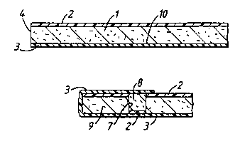
Figure 1 shows a cross-section through an edge region
of a cut-out blank of a li~uid-packaging laminate of a first
kind,
Figure 2 is a view similar to Figure 1, ~ut with the
edge region milled away to a desired profile,
Figure 3 is a view similar to Figure 1, but with the
relevant edge zone folded-over and pressure-sealed to the
remainder of the blank,
Figure 4 is a view similar to Figure 2, but of an edge
AMENDED ~SHFFT

PCT/SXIVING/D14 21 834C5
region of a cut-out blank of a liquid-packaging laminate of
a second kind,
Figure 5 is a view similar to Figure 3, but of the
blank of Figure 4,
E?ICED SHEET

WOg5/23061 2 1 ~ 3 4 ~ 5 PCT~Bssmn113
Figure 6 is a diagrammatic cross-section through a
liquid packaging carton made from the blank of Figures 4 and
5,
Figure 7 is a diagrammatic side elevation of an
apparatus forming on the blank the edge zone of Figure 3 or
5, and
Figure 8 shows a diagrammatic, fragmentary section
taken on the line VIII-VIII of Figure 7, with the apparatus
forming the edge zone of Figure 3.
BEST MODE FOR CAKK~ lN~ O~T T~E l~V~N ~ON
Referring to Figure l, the blank, from which a gable-
topped or flat-topped liquid-packaging carton is to be made,
is a laminate comprised of a layer l of paperboard coated on
both faces with layers 2 and 3 of thermoplastics, for
example polyethylene, of which the layer 2 is intended to
provide the inner surface and the layer 3 is intended to
provide the outer surface of the carton. If so desired,
the laminate may include one or more additional layers, for
example a gas barrier layer, such as EVOH or aluminium.
The blank has a cut edge 4 at which the paperboard l is
exposed so that, if the blan~ were to be folded and sealed
to form a carton with that cut edge 4 at the inside of the
carton and thus exposed to the liquid, for example milk, in
the carton, the liquid would be able to penetrate into the
paperboard and weaken the same and/or leak out through the
same. It is in order to prevent such penetration that the
cut edge 4 is skived and then pressure-sealed.
Referring to Figure 2, parallelly to the edge 4 are
milled a rectangular cut-away 5, a rectangular recess 6 and
a rectangular groove 7, thus leaving thereamong a
rectangular tongue 8 and a rectangular land 9. In forming
the items 5 to 7, the layers l and 2 are milled away to
substantially the hidden surface l0 of the layer 3 so as
substantially to expose the same. The recess 6 is of a
width slightly greater than the sum of the height and the
width of the land 9, whilst the width of the tongue is
slightly less than that of the groove 7.
Referring to Figure 3, the tongue 8 and the portion of

WO 95/23061 2 1 8 3 4 0 ~ PCI~/IB95/00113
the layQr 3 between the edgQ 4 and the land 9 have been
turned over the land 9 and the tongue 8 in~erted in the
groove 7. ~he tongue-ln-groove ~olnt 7, 8 serve~ to
prevent the folded-o~er edge zone ~rom moving back towards
it~ pre-rolding condltion prlor to pressure-~eallng thereof
to the remainder of the blan~. On such ~ealing, the
port~on o~ the layer 3 seQn between the tongue ~ and the
land 9 in Fi~ure 2 i~ pre~Qed sealingly agalnst the portlon
o~ the layer 2 included in the land 9, the sub~tantlally
exposed portion of the layer 3 in the groove 7 is pressed
seallngly against the portion of the layer 2 included in the
tongue 8, whilst the portion of the layer 3 pro~ecting
beyond the tongue 8 i~ pre~sed seallngly against the portion
of the layer 2 in the remainder of the blan~.
lS Referr~ng to Figure~ 4 to 5, the blank i~ a laminate
comprised o~ the layer 1 of paperboard coated on both faces
with the thermoplastics layers 2 and 3, but wlth a gas
barrier layer 12 of, for example alum~nium or EVOH, covering
the layer 2 and a layer 13 of thermoplastics, for example
polyethylene, covering the layer 12. Again, to ~orm the
ltems 5 to 7, the layer~ 1 and 2 are mllled away to
substantially the surface 10. Folding-over and pressure-
sealing are per~ormed aQ for tho embodiment of Flgures 1 to
3, to give the liquid-proof edge shown in Figure 5. As
~hown in Figure 6, the opposite edge zone 14 of th~ blank is
pre~sure-8ealed to the edge of F~gure 5, with the layer 13,
~n part~cular, ~eing sealed to it~elf, ~o that th~ barrier
layer 12 substantially completely encircle~ the interior of
th~ carton.
Re~erring to Figure~ 7 and 8, the apparatus includes a
milllng station 20 follow~d by a ~old~ng-o~Qr stat~on 21 and
a sealing station 22. At the milling stat~on 20 are two
dri~Qn horizontal rollQ 23 and 24 which grippingly ad~ance
the blank 1-3 between them, the lower roll, 24, belng
rotatably mounted upon a turntable arm 25 urged re~iliently
upwardly by a pneumatic piston-and-cylinder device 26 a~out
a horizontal pivot 27 on a ca~ing 2~. The roll 23 i8
rotatably mounted on an arm 29 turnable about a horizontal

WO ~5/23061 PCT/IB951()l)113
2 1 ~3405
pivot ~0 on the casing 27. A conical pin 31 effective
between the casing 27 and the arm 29 permits adjustment for
differing thicknesses of laminate. Three horizontal
cylindrical milling cutters 31 to 33 fixed to a horizontal
drive shaft 34 form in the blank the cut-away 5, the recess
6 and the groove 7, respectively. A suction mouthpiece 35
removes the debris resulting from the milling. A series of
pairs of upper and lower driven rolls 36a, 36b to 44a, 44b
advance the blank between them, while bringing the tongue 8
and the portion of the layer 3 between the edge 4 and the
land 9 in stages to a stage in which the tongue 8 ls
received in the groove 7. A series of pairs of upper and
lower driven rolls 45a, 45b to 48a, 48b then advance the
blank between them, while squeezing the edge zone, thereby
mechanically to ~am the tongue 8 into the groove 7, to ~eal
the edge zone. The upper rolls 36a to 44a are mounted upon
a support 49, whilst the upper rolls 45a to 48a are mounted
upon a separate support 50. The two supports 49 and 50 are
acted upon by respective pneumatic piston-and-cylinder
devices 51 and 52 which serve to maintain constant nip
pressures for the folding rolls 36 to 44 and for the sealing
rolls 45 to 48.
Although the sealing station (45 to 4~) could employ
heat as well as pressure for sealing of the edge zone, a
particular advantage of the system described with reference
to the drawings is that the use of heat is dispensed with
and the system relies upon mechanical pressure to produce
the sealing effect. Thus, the additional running and
maintenance costs involved in the use of heat can be
avoided.
LN~S-.~IA~ APPLICABl~lTY
The present invention is particularly applicable to the
packaging field, especially to webs or blanks from which
gable-top or flat-top, liquid-packaging cartons are to be
produced.

Dessin représentatif
Une figure unique qui représente un dessin illustrant l'invention.
États administratifs

2024-08-01 : Dans le cadre de la transition vers les Brevets de nouvelle génération (BNG), la base de données sur les brevets canadiens (BDBC) contient désormais un Historique d'événement plus détaillé, qui reproduit le Journal des événements de notre nouvelle solution interne.

Veuillez noter que les événements débutant par « Inactive : » se réfèrent à des événements qui ne sont plus utilisés dans notre nouvelle solution interne.

Pour une meilleure compréhension de l'état de la demande ou brevet qui figure sur cette page, la rubrique Mise en garde , et les descriptions de Brevet , Historique d'événement , Taxes périodiques et Historique des paiements devraient être consultées.

Historique d'événement

Description Date
Inactive : CIB expirée 2017-01-01
Inactive : CIB de MCD 2006-03-12
Inactive : Renseign. sur l'état - Complets dès date d'ent. journ. 2003-04-29
Inactive : Morte - RE jamais faite 2003-02-21
Réputée abandonnée - omission de répondre à un avis sur les taxes pour le maintien en état 2003-02-21
Demande non rétablie avant l'échéance 2003-02-21
Inactive : Abandon.-RE+surtaxe impayées-Corr envoyée 2002-02-21
Inactive : Demandeur supprimé 1997-10-24
Demande publiée (accessible au public) 1995-08-31

Historique d'abandonnement

Date d'abandonnement Raison Date de rétablissement
2003-02-21

Taxes périodiques

Le dernier paiement a été reçu le 2002-01-28

Avis : Si le paiement en totalité n'a pas été reçu au plus tard à la date indiquée, une taxe supplémentaire peut être imposée, soit une des taxes suivantes :

  • taxe de rétablissement ;
  • taxe pour paiement en souffrance ; ou
  • taxe additionnelle pour le renversement d'une péremption réputée.

Veuillez vous référer à la page web des taxes sur les brevets de l'OPIC pour voir tous les montants actuels des taxes.

Historique des taxes

Type de taxes Anniversaire Échéance Date payée
Enregistrement d'un document 1996-10-03
TM (demande, 3e anniv.) - générale 03 1998-02-23 1998-01-27
TM (demande, 4e anniv.) - générale 04 1999-02-22 1999-01-19
TM (demande, 5e anniv.) - générale 05 2000-02-21 2000-01-25
TM (demande, 6e anniv.) - générale 06 2001-02-21 2001-01-25
TM (demande, 7e anniv.) - générale 07 2002-02-21 2002-01-28
Titulaires au dossier

Les titulaires actuels et antérieures au dossier sont affichés en ordre alphabétique.

Titulaires actuels au dossier
ELOPAK SYSTEMS AG
Titulaires antérieures au dossier
LARS LYNGAAS
RAGNAR HARALD SAGVIK
Les propriétaires antérieurs qui ne figurent pas dans la liste des « Propriétaires au dossier » apparaîtront dans d'autres documents au dossier.
Documents

Pour visionner les fichiers sélectionnés, entrer le code reCAPTCHA :


Pour visualiser une image, cliquer sur un lien dans la colonne description du document. Pour télécharger l'image (les images), cliquer l'une ou plusieurs cases à cocher dans la première colonne et ensuite cliquer sur le bouton "Télécharger sélection en format PDF (archive Zip)" ou le bouton "Télécharger sélection (en un fichier PDF fusionné)".

Liste des documents de brevet publiés et non publiés sur la BDBC .

Si vous avez des difficultés à accéder au contenu, veuillez communiquer avec le Centre de services à la clientèle au 1-866-997-1936, ou envoyer un courriel au Centre de service à la clientèle de l'OPIC.


Description du
Document 
Date
(aaaa-mm-jj) 
Nombre de pages   Taille de l'image (Ko) 
Dessin représentatif 1997-09-18 1 6
Page couverture 1996-12-04 1 16
Abrégé 1995-08-31 1 48
Description 1995-08-31 6 267
Revendications 1995-08-31 4 144
Dessins 1995-08-31 3 80
Rappel - requête d'examen 2001-10-23 1 118
Courtoisie - Lettre d'abandon (requête d'examen) 2002-04-04 1 172
Courtoisie - Lettre d'abandon (taxe de maintien en état) 2003-03-24 1 178
Taxes 2002-01-28 1 33
Taxes 2000-01-25 1 32
Taxes 2001-01-25 1 31
Taxes 1998-01-27 1 42
Taxes 1999-01-19 1 38
Taxes 1997-02-21 1 32
Taxes 1997-01-27 1 33
Rapport d'examen préliminaire international 1996-08-15 7 199
Courtoisie - Lettre du bureau 1997-02-28 1 50
Courtoisie - Lettre du bureau 1996-10-17 1 41