Note : Les descriptions sont présentées dans la langue officielle dans laquelle elles ont été soumises.
~1~3q~1 ' -' -
Attorney Docket No. 80-104P-PCT
IIINGELESS INTRAOCULAR LENS MICROCARTRIDGES
RE:LATED APPLICATION(S)
This is a Continuation-In-Part of U.S. patent application Serial No.
507/953,251, filed on September 30, 1992, now abandoned.
FIELD OF TIIE INVENTION
This invention relates to hingeless type intraocular lens microcartridges for
use with surgical instruments for implantation of deformable intraocular lenses
into the eye.
10I~ACKGROUND OF TIIE rNVENTION
Intraocular lenses have gained wide acceptance in replacement of human
crystalline lenses after a variety of cataract removal procedures. The human
crystalline lens is generally recognized to be a transparent structure having a
thickness of about five (5) millimeters and a diameter of about nine (9)
! ~ ~
q ~ ~
millimeters. The lens is suspended behind the iris by zonula fibers which connect
the lens to the ciliary body. A lens capsule surrounds the lens, the
front portion of the capsule being commonly known as the anterior capsule and
the back portion commonly known as the posterior capsule.
Numerous procedures for the removal of cataracts have been developed
in which the lens is removed from the eye and replaced by an artificial lens
implant. The extraction procedure may generally be categorized as intracapsular
(in which the lens is removed together with the lens capsule) and extracapsular
(in which the anterior capsule is removed with the lens, and the posterior capsule
is left intact).
Since Ridley implanted the first artificial lens in about 1949, the problems
~oci~ted with cataract extraction and lens implantation have received a great
deal of attention from ophthalmic surgeons. Various types of artificial lenses
have been proposed, and appropliate surgical procedures have been developed
which strive to reduce patient discomfort and to reduce postoperative
complications. Reference is made in this connection to Pseudophakos by N. Jaffe
et al.; "History of Intraocular Implants" by D.P. Choyce (Annals of
Ophthalmology, October 1973); U.S. Patent No. 4,251,887 issued to Anis on
February 24, 1981; U.S. Patent No. 4,092,743 issued to Kelman on November
8, 1977; "Comparison of Flexible Posterior Chamber Implants", presented at the
American Intraocular Implant Society Symposium April 23, 1982, by Charles
Berkert, M.D.; and "the Simcoe Posterior Lens" (Cilco, Inc. 1980); U.S. Patent
No. 4,573,998 issued to Mazzocco on March 4, 1986, and U.S. patent
application Ser. No. 400,665 for "Improved Fixation System for Intraocular Lens
Structures'', filed July 22, 1982, U.S. Patent No. 4,702,244 issued to Mazzocco
on October 27, 1987; and U.S. Patent No. 4,715,373 issued to M:~7.70cco et al.
on Decemher 29, 1987, which disclosures are hereby incorporated by reference.
a
~1~34
Of particular interest in the context of the present invention is the
development of surgical techniques requiring relatively small incisions in the
ocular tissue for the removal of cataracts as disclosed in U.S. Patent No.
4,002,169 and U.S. Patent No. 3,996,935. A number of skilled artisans
have disclosed intraocular lens structures comprising an optical zone portion
generally made of rigid materials such as glass or plastics suitable for optical use.
However, one of the principal disadvantages of the conventional rigid
intraocular lens is that implantation of the lens requires large incisions in the
ocular tissue. This type of surgical procedure leads to a relatively high
0 complication rate, among other disadvantages. For instance, the serious dangers
associated with implantation of a rigid lens structure include increased risk ofinfection, retinal det~chm~nt, and laceration of the ocular tissue, particularly with
respect to the pupil.
Accordingly, those skilled in the art have recognized a significant need for
surgical tools for implantation of deformable intraocular lens structures which
afford the clinical advantages of using relatively small incision techniques, which
provide a safer and more convenient surgical procedure. In particular, those
skilled in the art of deformable intraocular lenses and methods and devices for
implantation, have also recognized a significant need for surgical tools which do
not require widening of the wound made in the ocular tissue during or after
implantation, but will deform the intraocular lens to a predetermined cross section
in a stressed state and which allow the ophthalmic surgeon to inspect the lens
prior to implantation without manipulation in the eye. The present invention
fulfills these needs.
2 5 The present invention was derived by improving the methods and devices
in the above-identified patents, specifically the methods of U.S. Patent No.
4,573,998 and the devices of U.S. Patent No. 4,702,244.
/
2 ~
SUMMARY OF TIIE INVENTION
An object of the present invention is to provide an improved intraocular
lens microcartridge.
Another object of the present invention is to provide a intraocular lens
5micr~,l,idge for use with a surgical device for implantation of a deformable
intraocular lens into the eye through a relatively small incision made in the ocular
tissue, said lens mic~oc~l-idge comprising a lens holder portion having a lens
receiving portion for receiving and holding the deformable intraocular lens, anda nozzle portion connected to and extending from said lens holder portion, said
lens holder portion and said nozzle portion having a continuous passageway
extending thelethrough.
A further object of the present invention is to provide an intraocular lens
microcartridge with a hingeless construction.
An even further object of the present invention is to provide an intraocular
lens microcartridge having a lens receiving portion that is fixed relative to a
nozzle portion thereof.
Another further object of the present invention is to provide an intraocular
lens microcartridge with a lens receiving portion having an oval shaped barrel
configuration.
2 o Another object of the present invention is to provide an intraocular lens
microca,l,idge having a lens receiving portion provided with a longitudinal slottherethrough to allow a deformable intraocular lens to be loaded through the slot.
A further object of the present invention is to provide an intraocular lens
microcartridge having a lens receiving portion provided with a longitudinal slottherethrough and extending to an end of a lens holder portion to allow a
deformable intraocular lens to be loaded through the slot.
5 ~
An even further object of the present invention is to provide an intraocular
lens micl~,ca-lridge having a lens receiving portion provided with a longitudinal
- slot therethrough and extending from a rounded end to an end of a lens holder
portion to allow a deformable intraocular lens to be loaded through the slot.
Another further object of the present invention is to provide an intraocular
lens microcallridge with a lens holder portion including a transition portion with
an oval shaped barrel located between a lens receiving portion and a nozzle
portion.
Another object of the present invention is to provide an intraocular lens
microcartridge with a lens holder portion including a transition portion with anoval shaped barrel defined by inwardly tapering side walls that taper from the
dimensions of the lens receiving portion to the dimensions of the nozzle portionlocated bel~n a lens receiving portion and a nozzle portion.
A further object of the present invention is to provide an intraocular lens
15 mic~c~l,idge with a lens receiving portion provided with an oval shaped barrel,
a transition portion provided with an oval shape barrel with inwardly tapering
sides, and a nozzle portion provided with an inwardly tapering conical
passageway defining a continuous passageway through the microcartridge.
An even further object of the present invention is to provide an intraocular
2 o lens microcartridge with an oval shaped barrel of a transition portion defined by
conical shaped inner side walls, a subst~n~i~lly flat bottom wall, and a top wall
having a downwardly extending protrusions that tapers so as to become less
pronounced when extending from a lens receiving portion to a nozzle portion.
Another further object of the present invention is to provide an intraocular
lens microcartridge with an oval shaped barrel of a transition portion defined by
conical shaped inner side walls, a substantially flat bottom wall, and a top wall
~:183~5 1
having a downwardly extending protrusion that tapers so as to become less
pronounced when extending from a lens receiving portion to a nozzle portion
wherein the inner top wall is substantially parallel to the inner bottom wall.
Another object of the present invention is to provide an intraocular lens
microcartridge having an oval shaped barrel in a receiving portion having greater
cross-se~tion~l dimen~;ons relative to cross-sectional ~limçncions of an
entranceway into a nozzle portion thereof.
A further object of the present invention is to provide a intraocular lens
microcartridge for use with a surgical device for implantation of a deformable
intraocular lens into the eye through a relatively small incision made in the ocular
tissue, the lens microcartridge comprising a lens holder portion having a lens
receiving portion for receiving and holding the deformable intraocular lens, anda nozzle portion connected to and extending from said lens holder portion and
having a tapering configuration, the lens holder portion and the nozzle portion
having a continuous passageway extending therethrough.
An even further object of the present invention is to provide an intraocular
lens microcartridge having an outer wall of a nozzle portion tapering downwardlyfrom a lens holder portion to a free end of the nozzle portion.
Another further object of the present invention is to provide an intraocular
lens microcartridge having an inner wall and an outer wall of a nozzle portion
lapeling together is a direction towards a free end of the nozzle portion providing
a wall ~hi~knçss that tapers thinner from the lens holder portion to the free end
of the nozzle portion.
Another object of the present invention is to provide an intraocular lens
microcartridge having an extension of lhe lens microcartridge for ~ligning the lens
microcartridge in a surgical device for implantation of the deformable intraocular
lens.
218~4~1
A further object of the present invention is to provide an intraocular lens
microcartridge having an extension of the lens microcartridge for aligning the lens
microc~llidge in a surgical device for implantation of the deformable intraocular
lens whe~in the extension protrudes upwardly from the lens holder portion.
An even further object of the present invention is to provide an intraocular
lens microcartridge for use with a surgical device for implantation of a
deformable intraocular lens into the eye through a relatively small inci~;on made
in the ocular tissue, the lens microcartridge comprising a lens holder portion
having a lens receiving portion defined by a cylinder having a longitudinal slottherethrough for receiving and holding the deformable intraocular lens, the lensholder having a transition portion defined by a tapering inwardly interior wall
extending from said lens receiving portion, a nozzle portion connected to and
extending from the transition portion of the lens holder portion, the lens holder
portion and the nozzle portion having a continuous passageway extending
therethrough, and an extension of the lens holder portion for aligning tlle lensmicr~l.idge in the device for implantation of the deformable intraocular lens.
The present invention is directed to methods and devices for implantation
of intraocular lenses into the eye. In particular, the present invention is directed
to hingeless type intraocular lens microcartridges.
2 o A surgical device according to the present invention includes the
combination of a lens holder and a holder for the lens holder or lens
microcartridge. The preferred lens microcartridge comprises the combination of
a lens receiver and an implantation nozzle. The lens receiver in one preferred
embodiment is defined by a split tubular member having a fixed tubular portion
with an extension connected to a moveable tubular portion with an extension at
a hinge. This configuration allows the microcartridge to be opened to accept a
2 ~4 ~ L
deformable intraocular lens, and closed to condense the lens into the passageway.
The split tubular portion is col-nected to a nozzle with a continuous passagewaypassing through the tubular member and the nozzle.
Another p~fe-led embodiment is a hingeless type microcartridge into
5 which a lens is carefully loaded prior to being placed in the receiver of the
surgical implantation device.
The lens holder is inserted into a holder (i.e. surgical implantation device)
having means for driving or manipulating the lens from the lens holder into the
eye. In the preferred embodiment, the holder is provided with a plunger for
10 driving the lens from the lens holder into the eye. ~urther, the holder is
configured to receive the microcartridge having a nozzle of the hinged or
hingeless version.
The preferred holder includes means to prevent the microcartridge from
rotating within the holder, and means for preventing the plunger from rotating
5 within the holder. The means for preventing rotation of the microcartridge within
the holder can be define by providing the microcartridge with one or more
extensions that cooperate with the opening of the receiver of the holder to prevent
rotation. The means for preventing the plunger from rotating within the holder
can be defined by providing the plunger and a sleeve within the holder with a
20 particular cross-sectional shape that prevents rotation, for example, a half-circle
shape.
The preferred holder includes a plunger with a threaded cap cooperating
with a threaded sleeve of the holder body for dialing the plunger forward withinthe holder for precise and accurate movement of the lens during the implantation25 process. The holder is configured so that the plunger can be moved a
predetermined distance by sliding mo~ion within the holder body followed by
engagement of the threaded cap of the plunger with the threaded s1eeve of the
holder body to continue the forward progress of the plunger tip.
2~8~
The preferred plunger tip is defined by a faceted tip having various
surfaces for moving and manipulating the lens from the lens holder and within the
eye. The tip is designed to provide a clearance between the tip and the inner
surface of the passageway through lens holder to accommodate the trailing hapticand prevent damage thereto. Once the lens is inserted into the eye, the tip can
be used to push and rotated the lens into proper position within the eye.
A method according to the present invention includes lubricating the
surface of a deformable intraocular lens with a surgically compatible lubricant,and loading the lens into a microcartridge in the opened position. The
lo microcartridge is closed while conden~ing the lens by a folding action into a
shape so that it can be forced through the passageway in the miclocall-idge. Themicrocartridge is inserted into the holder with the plunger retracted.
The plunger is moved forward in a sliding manner by pushing the plunger
forward while holding the holder body still. This action forces the lens from the
tubular member portion of the microcartridge into the nozzle portion. At this
point the threads of the threaded end cap of the plunger engage with the threadsof the threaded sleeve. The threaded end cap is rotate slightly to engage the
threads. The device is now ready for the implantation process.
The nozzle of the microcartridge is placed through a small incision in the
2 o eye. The threaded end cap of the plunger is rotated or dialed to further advance
the lens forward through the nozzle and into the eye. The threaded end cap is
further dialed to exposed the tip of the plunger within the eye and push the lens
into position. The tip can be used to also rotate the lens within the eye for
positioning of the haptics.
~18~4~1
I~R~EF DESCI~II'TION OF T~IE DI~AWINGS
Figure 1 is a perspective view of one embodiment of device according to
the present invention with a lens holding microcartridge positioned in the device
for implantation of deformable lens structures for placement in the eye.
Figure 2 is a perspective view of the surgical device depicted in Pigure 1
with the plunger retracted, and with the lens holding microcartridge removed.
Figure 3 is a side view of the device depicted in Figure 2, with the
plunger in the e-Ytende~ position.
Figure 4 is a side elevational view of the device shown in Figure 1.
Figure 5 is a detailed longitudinal cross-sectional view of the device shown
in Pigure 4.
Figure 6 is a detailed transverse cross-sectional view of the device, as
indicated in Figure 5.
Figure 7 is a det~il~l end view of the device, as indicated in Figure 5.
Figure 8 is an enlarged detailed left side elevational view of the tip of the
plunger in the spacial orientation as shown in Figure 1.
Figure 9 is an enlarged detailed end view of the tip shown in Figure 8.
Figure 10 is an enlarged detailed top planar view of the tip of the plunger.
Figure 11 is an enlarged det~iled right side elevational view of the tip of
the plunger in the spacial orientation, as shown in Figure 4.
Figure 12 is an enlarged detailed bottom view of the tip of the plunger in
the spacial orientation, as shown in Figure 1.
Figure 13 is a perspective view of a lens for use in the present invention.
Figure 14 is a pe-~peclive view of another type of lens for use in the
2 5 present invention.
Pigure 15 is a side view of the lens shown in Figure 13.
r~
2 1 ~4~1
Figure 16 is a pe,~,ecli-/e view of the lens holding microcartridge in the
open position to allow a lens to be loaded therein.
Figure 16A is another ~.~)eclive view of the lens holding microcartridge
in the open position.
sFigure 17 is a rear end elevational view of the lens holding microcartridge
in the open position.
Figure 18 is a front end elevational view of the lens holding
microcartridge in the open position.
Figure 19 is a rear end elevational view of the lens holding microcartridge
in the closed position.
Figure 20 is a front end elevational view of the lens holding
mic,~llidge in the closed position.
Figure 20A is a detailed end view of the nozzle showing three (3) slots of
different length equally spaced about the circumference of the tip.
5Figure 20B is a detailed perspective view of the tip showing the three (3)
slots of different length.
Figure 20C is a detailed side view showing the beveled tip.
Figure 21 is a top planar view of the lens holding microcartridge in the
open position.
Figure 22 is a side elevational view of the lens holding microcartridge in
the closed position.
Figure 23 is a rear end elevational view of the lens holding microcartridge
in the closed position.
Figure 24 is a broken away side view of the device showing the lens
holding microcartridge in relationship to the plunger in the retracted position.Figure 25 is a broken away side view of the device showing the lens
holding microcartridge in relationship to the plunger in a partially extended
pos1tion.
34~1
Figure 26 is a broken away side view of the device showing the lens
holding microcanridge in relationship to the plunger in a fully extended position.
Figure 27 is a pe.~pecli~e view showing the device positioning a
deformable intraocular lens within the eye.
5Figure 28 is a cross-sectional view of an eye showing the positioning of
the deformable intraocular lens into position in the eye by the surgical device.Figure 29 is a cross-sectional view of an eye showing the positioning of
the deformable intraocular lens into a different position in the eye by the surgical
device.
loFigure 30 is a side elevational view of an alternative embodiment of the
lens holding microcanridge provided with a beveled tip.
Figure 31 is a rear end elevational view of another alternative embodiment
of the lens holding microcartridge provided with grooves in the passageway to
facilitate folding the canridge in an open position.
15Figure 32 is a rear end elevational view of another alternative embodiment
of the lens holding microcanridge provided with grooves in the passageway to
facilitate folding the cartridge in a closed position.
Figure 33A is a front end elevational view of the nozzle of an alternative
embodiment of the lens holding microcartridge.
20Figure 33B is a front end elevational view of the nozzle of a funher
alternative embodiment of the lens holding microcanridge.
Figure 34 is a longitudinal cross-sectional view of a plefe-.ed embodiment
of the hingeless intraocular lens microcartridge according to the present invention.
Figure 35 is a top view of the hingeless intraocular lens microcartridge,
25as shown in Figure 34.
Figure 36 is a panial broken away top view of the hingeless intraocular
lens microcanridge, as shown in Figure 35.
218~
Figure 37 is a cross-seetional view of the hingeless intraocular lens
microcartridge at location 37-37, as shown in Figure 34.
Figure 38 is a cross-sectional view of the hingeless intraocular lens
microc~llidge as indic~ at 38-38, as shown in Figure 34.
Figure 39 is a front elevational view of the hingeless intraocular lens
microcartridge shown in Figures 34-37.
Figure 40 is a longitudinal cross-sectional view of the hingeless intraocular
lens microcartridge, as shown in Figure 34, with an intraocular lens plaeed on top
of the microcalllidge ready for insertion therein.
Figure 4l is a rear elevational view of the microcartridge, as shown in
Figure 40, with the intraocular lens not yet deformed for inserting into the
mierocartridge.
Figure 42 is a rear elevational view of the microcartridge, as shown in
Figure 40, with the intraocular lens panial deformed and bent at the center being
inserted into the mierocartridge.
Figure 43 is a rear elevational view of the mierocartridge, as shown in
Figure 40, with the intraocular lens fully deformed and inserted inside the
mierocartridge.
Figure 44 is a partial view of an alternative tip portion of the
microcalllidge having a beveled end.
Pigure 45 is a partial view of another alternative tip portion of the
microcartridge having a heat deformed tip.
DETAILED Dli~SCl~IPIION OF rREFERRED EMnODIMENTS
The present invention is directed to a system including methods and
devices for implantation of deformable intraocular lens structures for surgical
pl~ cement in the eye.
21~
14
An inventive device according to the present invention comprises a holder
having a receiver, a lens holder that can be removably inserted into the receiver
of the holder, and means such as a moveable plunger disposed within the holder
to force and manipulate the lens from the lens holder ihto the eye.
Preferably, the lens holder is defined by a lens holding microcartridge for
receiving the lens structure. Further, the microcartridge is preferably a structure
configured to be opened and closed. The preferred embodiment of the
miclocalllidge receives a lens having prescribed memory characteristics when
in the open position, and performs the function of folding or deforming the lensstructure into a conden~ed configuration when being closed. Alternatively, the
micr~caltlidge can be a structure having a passageway defined by a continuous
walled annulus, and a lens could be inserted into the passageway from the end ofmictoc~llidge by co".p-~ssing, rolling, folding, or combination of these
techniques prior to insertion into the microcartridge.
Once a lens is positioned into the microcartridge, the microcartridge is
positioned into a plunger device. The assembled device maintains the lens in itscondensed configuration during insertion into the eye yet permits the deformed
lens to return to its original configuration, size and fixed focal length once
implanted in the eye, thereby providing a safe, convenient, and comfortable
surgical procedure.
A preferred embodiment of a deformable intraocular lens implantation
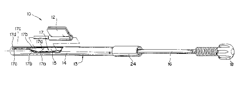
device 10 according to the present invention is shown in Figures 1, 2 and 3. Theimplantation device comprises a microcartridge 12 disposed within a holder 13
comprising a holder body 14 with a receiver 15, and a moveable plunger 16. In
Figure 1, the receiver 15 is defined by an opening 17 through the wall of the
holder body 14 of the size and shape shown in Figures 1 and 2. The opening 17
is defined by parallel edges 17a, 17a, which are sufficiently spaced apart to allow
the microcartridge 12 to be loaded into the receiver 15 of the holder 13, tapered
f.-s~
5 1
edges 17b, clamping edges 17c, and stop edge 17d. In Figure 1, the
microc~llidge 12 is positioned in the receiver 15 between the clamping edges 17cwith the plunger extending through the microcartridge 12 in a position, for
example, after a lens imp1~n~1ion procedure.
In Figure 2, the lens holding microcartridge 12 is shown removed from
the holder 13 with the plunger 16 in a retracted position for allowing the
microcartridge 12 cont~ining a loaded lens and its haptic to be inserted within the
holder 13. In Figure 3, the holder 13 is shown with the plunger 16 in the
e~tended position without the microcartridge 12 for purposes of illustration of the
Co~ o~ tS.
The plunger 16 is fitted with a threaded end cap 18 at one end, and fitted
with a tip 20 at an opposite end. The threaded end cap 18 is provided with a
plurality of grooves 22 to a allow a person to tightly grip the cap 18 with his or
her finger tips. The threaded end cap 18 is received within a threaded sleeve 24of the insert holder 14. The threaded end cap 18 can be a separate component
- ~t~^hed to the insert holder 13, or integral therewith, as shown in the construction is Figure 5.
The plunger 16 is installed within the holder 13 in a manner to allow the
plunger to be reciprocated therein. In the illustrated embodiment, the plunger
2 o 16 is supported for sliding movement within the holder 13 by guide 26, as shown
in Figures 5 and 6. The outer dimension of the guide 26 is approximately the
same size as the inner dimensions of the holder 13 to allow the guide to be
inserted within the insert holder. During construction, the guide 26 is insened
within the holder 13, and locked into position by pin 28 insened into a predrilled
hole in both the wall of the holder 13 and guide 26.
( ' ~
2 1 ~
The cross-sectional shape of the plunger 16 as well as the shape of the
inner surface of the guide 26 are approximately a half-circle, as shown in Figure
6. This arrangement prevents the plunger 16 from rohting within the holder 13
to m~int~in the orientation of the tip 20 relative to the holder 13 during operation.
The threaded end cap 18 is connected to the plunger 16 in a manner to
allow the threaded end cap 18 to be rotated relative to the plunger 16. For
example, the left end of the plunger 16 (Figure 5) is provided with a threaded
extensiQn 30, which is secured to the threaded end cap 18 by a nut 32.
Spe~ific~lly, the threaded end cap 18 is manufactured with
external threads 34 and a longitudinal center bore 36 that ends on the right side
of the threaded end cap 18 leaving a wall 38.
The wall 38 is provided with a hole slightly larger than the outer diameter
of the threaded extension 34 to allow the threaded end cap 18 to freely rotate on
the plunger 16 while being secured to the end of the plunger 16. During
construction, the nut 32 is inserted through the center bore 36 and threaded onto
the extension 30 to secure the threaded end cap 18 to the plunger 16. A curved
cap 40 is press fitted into the end of the center bore 36 to seal the center bore 36
to prevent debris from entering therein during use.
The details of the tip arrangement are shown in Figures 7 to 12. The
plunger 16 is manufactured with an extension 42 supponing tip 20. The tip 20
~tlu~:lult; provides means for inserting the deformable intraocular lens into the eye
and manipulating the lens within the eye after the insertion step. For example,
the tip 20 is faceted in the manner shown in the figures. Specifically, the leftside of the tip 20 shown in Figure 8 is provided with a flat surface facet 42,
conical surface 44, and cylindrical surface 46. The right side shown in Figure
11 is provided with a concave surface facet 50.
~ 1 8 ~
The end face of the tip 20 is designed to push the lens into position once
inserted into the eye. For example, the end face is defined by a concave
cylindrical surface 52 shown in Figure 8.
Suitable deformable intraocular lens for use in the present invention are
shown in Figures 13 - 15. The deformable intraocular lens 54 shown in Figures
13 and 15 includes a lens body 56 with attachment means defined by a pair of
haptics 58 each having one end anchored in the lens portion 56 and a free end for
~tt~-~hment to the eye tissue. The deformable intraocular lens 60 shown in Figure
14 includes a lens body 62 and ~tt~chment means defined by a pair of lateral
lobes 64 of the lens portion 62.
The details of the preferred lens holding microcartridge 12 are shown in
Figures 16 - 20. The microcartridge 12 comprises a split tubular member 66
exte~l-ling to a continuous tubular member 67 and an implantation nozzle 68.
When the microc~l~idge is in a closed position, a continuous circular or oval
passageway of the same di~metçr extends through the split tubular member 66
through the continuous tubular member 67 and through the implantation nozzle
68. The microcartridge is preferably made of injection molded plastic such as
polypropylene The split tubular member 66 is defined by a fixed portion
70 and a moveable portion 72. The fixed portion 70 is fixed relative to the
imp!~nt~tion nozzle 68, and is defined by a tubular ponion 74 and extension 72.
The moveable portion 72 is moveable relative to the fixed portion 70 for openingand closing the split tubular member 66. The moveable portion 72 is defined by
a tubular portion 78 and extension 80. A hinge 82 is provided between the fixed
portion 70 and moveable portion 72. The hinge 82 is defined by reducing the
thickness of the walls of the tubular portion 74 and 75 at the hinge 82, as shown
in Figures 17, 18 and 19. The hinge 82 runs the length of the split tubular
me.mbçr 66 to allow the extension 76 and 78 to be split apart, or brought together
to open and close, respectively, the split tubular member 66.
r
18
The tubular portion 78 of the moveable pOniOn 72 is provided with a
sealing edge 84, which is exposed when the lens holding microcartridge 12 is
opened, as shown in Figure 16A, and seals with a similar sealing edge 86 (See
~igures 17 and 21) of the continuous tubular member 67 when the lens holding
microcartridge is closed.
The end of the tip 20 is provided with three (3) equally spaced slots 87a,
87b and 87c of different length provided about the circumference thereof, as
shown in Figures 20A and 20B. The slot 87a positioned at the top of the tip 20
is the shortest, slot 87c on the right side of the tip 20 is the longest, and slot 87b
on the left side is of medium length. The slots 87a, 87b, 87c cause the lens 54
to rotate as it exits the tip 20.
Other embodiments of the microcartridge 12 according to the present
invention are shown in Figures 30-33.
The micluc~llidge shown in Figure 30 is provided with a beveled tip 94
to facilitate entry of the tip through the incision in the eye during implantation.
The beveled tip 94 can be set at approximately forty-five (45) degrees relative to
the passageway through the microcartridge 12.
The embodiment of the microcartridge shown in Figures 31 and 32 is
provided with a set of grooves 96 provided inside the passageway therethrough.
2 o The grooves accommod~te the edges of the lens being loaded into the
micr~calllidge to facilitate bending of the lens. Specifically, the edges of the lens
are placed in the grooves 96 to prevent relative slippage of the edges with the
inner surface of the passageway through the microcartridge when the
microcartridge is being folded into the closed position.
L
~i~3~
The embo liment~ of the microcartridge shown in Figures 33A and 33B
each have a nozzle 68' having an oval cross-section with slots 87' differently
position as shown, respectively, again to facilitate entry through an incision in the
eye. Alternatively, the cross-section can be two half circles set apart and
5 conne~ted together rather than oval.
The various features of the microcartridges shown in Figures 16-21 and
30-33 can be used in various combinations to achieved an optimum design for a
particular application. However, all of these features are typically considered
improvements of the basic combination.
The coll,ponents of the device 10, except for the microcartridge 12, are
preferably fabricated from autoclavable material such as stainless steel or froma dispos~hle rigid plastic such as medical grade ABS or the like.
HINGELESS INTRAOCULAR LENS MICROCARTRIDGE
A preferred embodiment of the hingeless type intraocular lens
microcartridge according to the present invention are shown in Figures 34-43.
In this embodiment, the lens microcartridge 200 comprises a lens holder
portion 202 and a nozzle portion 204 connected to and extending from one end
of the lens holder portion 202. The lens microcartridge is provided with a
continuous passageway therethrough that extends from one end of the lens
microcartridge to the other end thereof. The lens holder portion 202 includes a
receiver portion 206 for receiving a deformable intraocular lens and a transition
portion 208, as shown in Figs. 35 and 36.
The receiver portion 206 is defined by a tubular member 210 provided
with an oval shaped barrel 212 having a longitudinal slot 214 therethrough. The
oval shaped barrel 212 has a cons~ant cross section or a gradually reducing cross
section throughout the length of the receiver portion 206. Further, the
longitudinal slot 214 has a rounded end 216 at one end, and an open end 218 at
an opposite end thereof.
The transition portion 208 is defined by a tubular member 220 with an
5 oval shaped barrel 222 having a cross section that tapers inwardly from the
receiver portion 206 to the nozzle portion 204. Specifically, the sides 224 of oval
shaped barrel 222 taper inwardly, as shown in Fig. 36, while the top surfaces 226
(i.e. defining grooves 226) and bottom surface 228 of the oval shaped barrel 222are parallel (i.e. not tapered), as shown in Fig. 34. Further, the top 226 is
10 provided with a downwardly extending protrusion 230 having curved sides that
are shaped to turn the edges of the deformable intraocular lens downwardly, as
shown in Fig. 37. The protrusion becomes less pronounces in a direction
extending towards the nozzle portion 204, and disappears at the nozzle portion to
a provide a continuous inner surface and transition from the lens holder 202
5 portion into the nozzle portion 204.
The grooves 226 in the receiver portion 206, as shown in Figure 38, are
defined by curled upper portions of the receiver portion 206 on either side of the
slot 214, and extend continuously to the grooves of the transition portion 208.
The lens microcartridge 200 is provided with an extension 232 for ~ligni"g
2 0 the lens microcartridge 200 in the device for implantation of the intraocular lens.
Specifically, the extension 232 is defined by plastic material that extends from the
lens holder portion 202, and is configured to snag fit in the slot of the device for
implantation of the intraocular lens. In the embodiment shown in Figs. 34-39,
the extension 232 has a rectangular side profile (See Fig. 34) and has a constant
25 thickness (See Fig. 35) along its length.
The manner in which the deformable inlraocular lens is inserted into the
lens microcartridge is illustrated in Figs. 40-43.
2~.~34.~.
A deformable intraocular lens 234 is loaded on top of the receiver portion
206 of the lens holder portion 202. The deformable intraocular lens 234 is forced
downwardly in the center thereof by implement or finger tip to reach the
configuration shown in Fig. 42. The deformable intraocular lens is further
5 pushed into the receiver portion 206 until it is fully inserted in the oval shaped
configuration shown in Fig. 43 with its outer surface wrapping around and in
contact with the sides 224, bottom 228, and top 226 of the receiver portion 206.The grooves defined by surfaces 226 hold the lens in position and guide it whilethe lens is being pushed through the microcartridge by the insertion instrument.10The edges of the deformable intraocular lens 234 contact with the
downwardly eYtç~ ng protrusion 230 in the top 226, and ride along the
protrusion 230 when being inserted through the lens microcartridge gently further
folding the lens as it enters into the nozzle portion 204.
An alternative nozzle portion 204' is shown in Figure 44 having a beveled
15end. A further alternative nozzle portion 204" is shown in Figure 45 having a
heat deformed tip with a beveled end. Specifically, the end of the nozzle is
heated and stretch to reach the shape and configuration shown.
METHODS OF IMPLANTATION
The surgical procedure begins by coating the lens with a surgically
2 0 compatible lubricant, and loading the lens into the microcartridge. For example,
as shown in Figure 21, a lens 54 having a lens body 56, a leading haptic 58a is
load into the microcartridge 12 while a trailing haptic 58b remains trailing outside
the microca,llidge in the manner shown. Specifically, the lens 54 is loaded
downwardly into the opened microcartridge 12 until it sits on the inner surfaces25 of the tubular portions 74 and 78, for example, with a pair of tweezers. The
outer circumferential surface of the lens 54 are held by edges 88 and 90 of the
~ 1 8 ~
22
tubular portions 74 and 78, respectively. The rear edge of the lens 54 is placedal)p~o,-imately at the rear edge of the microcanridge 12. The lens 54 is furthermanipulated to situate the haptics 58a and 58b in the manner shown. Specifically,
haptic 54a is positioned in a leading position and the other haptic 54b is
5 positioned in a trailing position outside with respect to the direction of
implantation, as indi~ted by the arrow.
Subsequently, the split tubular member 66 of the microcartridge 12 is
closed about the lens 54 by forcing the extensions 76 and 80 together with his or
her finger tips. The inner surfaces of the tubular portions 74 and 78 bend and
fold the lens 54 when the extensions 76 and 80 are forced together, as shown in
Figures 22 and 23. Due to the resilient nature of the deformable intraocular lens
54, the lens 54 conform to the curved inner surface of the tubular portions 74 and
78 without damage thereto, as shown in Figure 23.
The microcall.idge 12 containing the loaded lens 54 is inserted between
the edges 17a, 17a of the opening 17 into the receiver 15 of the holder 13. As
the mic~oc~llidge 12 is moved forward, the extensions 76 and 80 move past the
tapered edges 17b and come to a stop position between the clamping edges 17c
when front portions of the extensions 76 and 80 contact with the stop edge 17d.
The clamping edges 17c prevent rotation of the microcartridge inside the holder
13.
The user pushes the threaded end cap 18 forward while securing the holder
body 14 from movement, forcing the plunger 16 forward within the holder. As
the plunger 16 is moved forward, the tip 20 enters into the rear of the
microcartridge 12 and misses the trailing haptic 58B until the tip makes contactwith the loaded lens 54, as shown in Figure 24. As the plunger 16 is moved
forward in this manner, the lens 54 previously lubricated, is forced into the
implantation nozzle 68 of the microcartridge 12, as shown in Figure 25.
~3~
Once the lens 54 enters the implantation nozzle 68, the threads of the end
cap 18 contact with the threads of the sleeve 24 stopping further movement of the
plunger 14 forward in this manner. The end cap 18 is slightly rotated to engage
the threads of the end cap 18 with the threads of the sleeve 24. At this point, the
surgical device is ready for the implantation step. The nozzle is insert throughthe inci~;on in the eye, and the end cap 18 is rotated to continue the forward
movement of the plunger 16 by continued rotalion of the end cap 18 relative to
the holder body 14 to expel the lens from the noz~le into the interior of the eye,
as shown in Figure 26. This manner of screw advancement for moving the
lo plunger 16 forward provides for precise control and accuracy concerning forcing
the lens 54 through the remaining portion
of the tip 68 into the eye during the implantation procedure. The deformed lens
after exiting the nozzle 16 returns to its original configuration, full size and ffxed
focal length.
After the lens is inserted into the eye, the end cap 18 is further rotated to
fully expose the tip 20 of the plunger 16, as shown in Figures 28 and 29, to allow
the lens to be pushed forward, side manipulated to rotate the lens, and pushed
down to properly position the lens within the eye without the aid of other surgical
instruments.
The configuration of the tip 20 is important during the implantation
process. The faceted tip 20 provides a clearance between the tip 20 and the inner
surface of the passageway through the microcartridge 12 to accommod?~e the
trailing haptic 58b during movement of the lens within the microcartridge 12, asshown in Pigures 25 and 26. Specifically, there exists a sufficient clearance
2 5 between the flat surface facet 44 and the inner wall of the passageway through the
microcartridge 12. During the implantation process, the trailing haptic floats
around in the space between the extension 42 of the tip 20 and the inner wall ofthe passageway, as shown in Figure 25. This prevents any chance of damage to
21~34-~ ~
the trailing haptic, for example, by being caught between the tip 20 and the lens
54 during the implantation process. The leading haptic moves through the
passageway unimpeded during the implantation process preventing any damage
thereto.