Note : Les descriptions sont présentées dans la langue officielle dans laquelle elles ont été soumises.
2184~
WO 96/20790 PCrlUS95116404
DUl~L FLUID SPRAY NOZZLE
~a~-T'-P OF Ti~: INVENTIQN
Field of the Invention
The invention is directed to the field of spray
nozzles and, more particularly, to a dual fluid spray
nozzle adapted to produce a finQly atomized spray of
liquids .
DegcriPtion of thç Related Art
In many liquid spraying applications, it is desirable
to produce finely dl _ ' 7~d droplets of a liguid reagent.
For example, in semi-dry scrubbing systems used to remove
harmful gases such as acid flue gases ~.uduc~d by the
burning o~ coal or of wastes, small droplets of a
controlled size distrlbution optimize the mixing of the
reagent and the flue gases and rC~rtm~7e pe~fOLIlld~ ~ of the
gas mle~n~n~ process. Small droplets also ~va~uL~L~ more
readily and m;ntm17e the A1 :~onR of the reactor chamber
in which the liquid is sprayed, while the ~cc~ tion of
corrosive substances on the reactor walls is avoided.
The known dual fluid 6pray nozzles are generally
unable, however, to produce finely 2tomized droplets of
liquids without experiencing a number of te-~hn;c~l
problems. In a nozzle, the 1l1 ~ te~ and the corresponding
cross-sectional flow area of the fluid passages affect the
size distribution o~ the a ` i 7~A droplets . The f iner are
the flow passages, generally the finer are the sprayed
droplets. Accordingly, the diameter of the passages has
been reduced in the known dual fluid spray nozzles in an
effort to decrease the average size of the a~ i 7~A
droplets and produce a finely atomized spray.
This a~luacl~ to producing a finely atomized spray has
been inadequate for several reasons. For the atomization
of slurries, reducing the diameter of the fluid p lsc~ c
causes a c,uL~--C~ 1in5~ increase in the rate of ~loggtn~ of
the passâges by the slurry particles. The reduced Ai ~ ~ L~l
_ _
-
2~8~
WO 96/207gO PCIII~S9~116404
paC~a~eC effectively filter the particles and limit the
maximum size of particles which can physically pass through
them. rl o~g1 n~ is a ~, -' L~l problem assoclated with
the atomization of slurry materials, even though, for most
5 liquids, ~ ed solids are always present and may
ocr~cfrnf-lly cause clogging.
Accordingly, selecting the size of the flow passage5
in a spr~y nozzle involves 2 bf~1 ~nr~ n!J of the acceptable
droplet size distribution against the acceptable rate of
lO clogging of the nozzle. For slurries, clogging is so
severe that it is not possible to achieve the desired
droplet size distribution using the known dual spray
nozzles as the n~c~sCc~y flow passage diameter is too small
to be functional.
In addition to their rl og~; n~ characteristics, slurry
materials are also erosive and corrosive to the
conventional materials used to UUII~ Ll ~ L spray nozzles .
In order to reduce the clogging of nozzle pACR~es
during slurry spraying operations, it is theoretically
pssR~hle to increase the velocity o~ the a~ '71ng fluid
and the entrained slurry particles. Although this solution
theoretically redu~es clogging, at least when the slurry
particles are smaller than the A1~ of the passages, lt
ls inadequate because increasing the velocity
25 simult~n~o~cly increases the erosion rate of the passages.
Therefore, the practical upper limit of the operating
velocity is based on the acceptable level of wear of the
nozzle. If erosion is too severe at the velocity nf~r.~ ry
to prevent r1r,g~ing, then such velocity is ernnl ic;~11y
infeasible due to the shortened service life of the nozzle
and the ~,ULL. ~L~o.~ng in~leased r-~p1~( L costs.
FUL ~ , the atomization of slurries using dual
fluid spr2y nozzles is energy intensive, and increasing the
velocity of the aL '7~n~ fluid only further increases
energy usage as it increases the amount of energy re~auired
to input the a~ '7;n~ fluid and slurry into the nozzle.
Therefore, in view of the inadequacies of the known
.
WO 96~20790 ~ Q ~ ~ PCTIUS9~16404
dual fluid sprsy nozzles, there has been a need for a dual
fluid spray no2zle which is capable of producing a finely
atomized sprzly of a slurry at a reduced energy demand, and
of producing a finely a L i ~o spray at a reduced rate of
5 erosion of the nozzle.
SUMMARY OF ~rHE lhv Isn ~C..
The present invention has been made in view of the
above-described inadequacies of the known spray nozzles and
has as an object to provlde a dual fluid spray nozzle which
10 is capable of producing a finely atomized spray of a slurry
at a reduced energy demand.
Another object of the invention is to provide a dual
fluid spray nozzle which is capable of producing a finely
~ L ' 7e~i spray of a slurry at a reduced rate of erosion of
l5 the nozzle.
Additional objects and advc~l~LGyes of the present
invention will become apparent from the detailed
description and drawing figures which follow, or by
practice of the invention.
To achieve the objects of the invention, the dual
fluid spray nozzle in aucuLda--ce with a preferred
embodiment of the invention comprises a body which defines
a first atomization chamber, a first inlet in the body
through which an a i ' 7 1 ng fluld is introduced intû the
first atomization chamber, and a second inlet in the outer
wall through which a liquid to be atomized is introduced
into the first atomization chamber.
An initial atomization means is ~l Cposecl in the first
atomization chamber to initially atomize the liquid
inLludu~:d into the first atomization chamber via the
second inlet.
A nozzle tip is mounted to the body. The nozzle tlp
defines a plurality of discharge op~n; ngC through which an
atomized spray is dlscharged.
The dual fluid spray nozzle further comprises a plate
which forms a front wall of the first atomizatlon chamber.
WO 96/20790 ~ ~ 8 ~ a g s PCT/US9511640~
The plate and the noz~le tip define a second atomization
chamoer ~li croce~ relative to the first
atomization chamber. The plate defines a plurality of
p~ssas~R through which the initially a~ '7ed liguid passes
5 from the first atomization chamber into the second
atomization chamber and is further clL ' 79~1,
In ~c.,~.dance with another ~L~ ~ ed: ' _ "i t of the
invention, the dual fluid spray nozzle may comprise a
plurality of plates, forming additional atomization
0 rh~-' S, t~1CpoRed along the length of the nozzle. Each
plate preferably hss a reduced total cross-sectional area
of paRsAg~Ps relative to the preceding plate, so that the
velocity of the al '7~ng fluid and the liquid increase
through each surc~sc1 ve plate.
BRIEF Dk:~,K~ ON OF THE D~AWINGS
In the ~ ,~c. ylng drawings:
Fig. 1 is a cross-sectional illustration21 view of a
dual fluid spray nozzle in accordance with a preferred
: ~ ~i t of the invention in the environment of a gas
20 conduit;
Fig. 2 is a front view of the nozzle of Fig. 1
depicting the aL~ of the discharge openings in the
nozzle tip;
Fig. 3 is a view of the plate whlch forms the front
25 wall of the first atomization chamber of the nozzle,
depicting the arrangement of the passages in the plate:
Fig. 4 is a cross-sectional illustrational view of a
dual fluid spray nozzle in accordance with another
preferred ~ of the invention
Fig. 5 is a cross-sectional view in the direction of
line 5-5 of Fig. 4;
Fig. 6 is a cross-sectional view in the direction of
line 6-6 of Fis~. 4;
Fig. 7 illustrates an alternative pmhQ~ ~, of the
3 5 plate shown in Fig . 6;
Fig. 8 illustrates an alternative ~mho~l~ t of the
-
WO 96/20790 2 ~ 8 ~ ~ ~ 9 PCT/US95116404
plate shown in Fig. 3; and
Fig. 9 is a ~iLvs~-scctional view in the direction of
line 9-9 of Fig. 8.
I)ET~TTF.n v~-SI.;n~ . OF 'rHE Pn~r~nnl--v ~ ~ff~ r~ ~-
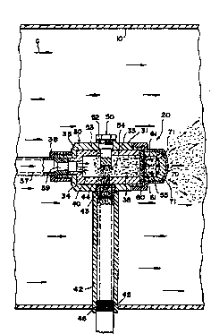
With reference to the drawing figures, Fig.
illustrates P dual fluid spray nozzle 20 in 2~0LdanC~ with
a pIeLeLLed c '~'i t of the invention. The spray nozzle
utilizes an a; '71n~ fluid to produce an a~ ;7ed spray of
a liquid.
The spray nozzle 20 is illusL.aLed rli 5po5Ptl in a
conduit 10 which contains a stream of gases "G". The
nozzle is particularly adapted to produce a finely aL i-7ecl
spray of a selected slurry composition, such as a lime milk
slurry comprised of lime and water. Lime milk is
conventionally used as a clPRn1ns medium in semi-dry gas
~-lP~ntn~ systems. The illustrated stream of gases may be
flue gases ~Lodu~i~d by the burning of coal in power plants
or of waste in incineration plants. As shown, the nozzle
produces a spray "S" of an atomized liquid which interacts
with the flue gases to remove undesired and harmful
,I.).~-~L~ such as sulfur dioxide, hydrochloric acid and
fluoridlc acid.
In accordance with the invention, the ~pray nozzle io
cOmprises a body 30. The body is preferably cylindrical
shaped and it comprises an outer housing 31 ,_ 5Pcl o:~ a
metallic material. The outer housing 31 is comprised of a
pair of opposed side walls 33, 34, and a rear wall 35,
which define a first atomization chamber 36. A liner 32
I~sDc~! of an erosion and corrosion resistant -ceramic
material or the like lines the outer housing 31.
An a l - 7; ng fluid supply line 37 is connected to the
rear wall 35 at the upstream end o~ the nozzle A
connector 38 secures the a; '7~n~ fluid supply line 37 to
the nozzle body. The a~ '7in~ fluid supply line has a
reduced ~ L~:i portion 39 in ~~ 1 cation with an
orifice 40 formed in the liner 32. The orifice 40 directly
2~Q~9
WO 96no790 PCTIUS95116404
i cates with the first atomlz2tion chamber 36 .
The al '71ng fluid is preferably pressurized air.
Other fluids such as steam and the like may optionally be
utilized in the nozzle.
A liquid supply line 41 is secured to the side wall 34
of the body by a cu~ e~LuL 42. As shown, the uulllle~ur 42
l nr~ a reduced ~ L~L portion 43 in , ~ ratiOn
with an orifice 44 formed in the liner 32. The orifice 44
~r 1 rateS directly with the first atomization chamber
36 . The connector 42 i nrl u~lDq interlor threads 45 to
engage mating threads 46 formed on the liquid supply line
41 .
In dccoL~ with the invention, the nozzle 20
comprises lnitial atomization means to initially atomize
the liquid after it is introduced into the first
atomization chamber 36 Yia the liquid supply line 41. The
initial atomization means is preferably a target bolt 50
which is adjustably secured to the side wall 33 of the
body, opposite to the orifice 44 . The target bolt ~ nrl ~ e~
a base 51 having exterior threads 52 to engage mating
threads (not shown) formed on the wall of an opening,
through which the target bolt extends, provided in the side
wall 33. A post 53 extends into the first atomization
chamber and includes a surface 54 which is aligned with the
orifice 44. Liquid inLLudu~;ldd into the first atomization
chamber through the orifice 44 immediately ~i n~ upon
the surface 54, and is broken-up into fl 1-- ts and large
droplets .
The target bolt 50 is preferably ~ , - 9 ~(~ of a wear
resistant material such as a ceramic and the like.
The resulting f i 1~ t~ and large droplets are further
broken-up by the a~ 171n~ fluid stream introduced into the
~irst atomization chamber 36 through the orifice 40. As
the at 7;n~ fluid moves past the surface 54, it shears
the slurry into smaller particles. The di ' 7Ing fluid
mixes with the sheared particles and transports them
through the first atomization chamber.
-
WO96/2079~ PCIIUS9~116404
The first atomization chamber 36 is further defined by
a front wall formed by a plate 60. A second atomization
chamber is deflned between the plate 60 and a nozzle tip 70
disposed at the discharge end of the nozzle.
In 3C~,C.LdC~ ;e with the invention, the plate 60 defines
a plurality of pi,qcSi~g-oq 61 through which the slurry
particles pass from the first atomization chamber 36 into
the second atomization chamber 55. Referring to Fig. 3,
the plate preferably defines five passayæs 61 arranged in
a circular pattern. The pi~CCA~pe 61 further shear and
reduce the size of the slurry particles before entering the
second atomization chamber. After passing through the
pi~c~-ciq~s 61, additional mixing of the slurry particles and
the ,aL ~7ing fluid occurs in the second atomization
chamber.
The p2s~ages 61 preferably have a tii: teL- larger than
approximately twice the diameter of the largest slurry
particles introduced into the first atomization chamber 36
through the orlfice 44. By forming the piqcciqg.,c of this
~ L, the bridging of two or more slurry particles in
the pAec~c is substantially yLc~enl~d~
As a further measure to prevent the clogging of the
. pi~R,Ri35J~R, before the slurry is intLu-luu~:d into the first
atomization chamber 36, it is preferably filtered to remove
the particles larger than approximately one-half the
t11; l..~:L of the passages 61. Lime milk particles are
filtered to a maximum ~ L of approximately 1. 5 mm,
- and, accordingly, the diameter of the passages 61 is
preferably at least approximately 3 mm.
The plate 60 may have a different number of passages
than five, and the r~RS~FIC may also be positioned in
different arriqn- t5 about the plate. For example,
referring to Fig. 8, the plate 60" defines four pi~cs~ s
arranged in a circular pattern, and a fifth centrally
located passage. The plate 60" is adapted to be used in
combination with a nozzle tip, 8uch as the nozzle tip 70 '
illustrated in Fig. 4, having; centrally located discharge
WO9C/20790 2~gd~ PCTIUS95116404
opening 71 ' .
Forming a plurallty of flow p~c~ c in the plate 60
ae~ar~ Llng the atomization rh~ 36 and 55 improves the
p~L r~ ", -, .. ., of the nozzle 20 in comparison to the known
nozzles in which only one passage is formed in the plate.
Mor0 particularly, at a given velocity of the a~
fluid and a given energy input to the nozzle, the dual
fluid spray nozzle in a~,uLdc~ t with the invention
~>Lc,duces an aL '7Pd spray of a ~ , ~Llvely smaller mean
particle size, and a particle size distribution defined by
smaller minimum and maximum sized particles. The energy
input is detprm~np~l by the rate of input of the aL 17in~
fluld and liquid into the nozzle, and the le~iye~:Llve
pressures of the ~L '71n~ fluid and liquid. The dual
fluid spray nozzle further produces an equivalent mean
~; i 7~d particle size and approximately the same particle
size distribution at a lower velocity of the atomizing
fluid, and a corr~pnn~n~ lower rate of erosion and a
lower energy demand.
The nozzle tip 70 defines a plurality of discharge
openings 7L which finally atomize the liquid before it is
discharged into the a~ yheL~. The discharge openings
also control the spray pattern of the atomized slurry such
that a substantially cone-shaped spray pattern "S" is
produced. To achieve such a pattern, the openings 71 are
oriented at an angle of preferably between about 3--7'
relative to the longitudinal axis of the nozzle as
illustrated in Fig. l.
As illustrated in Fig. 2, the nozzle tip 70 of the
dual fluid spray nozzle 20 defines eight openings 71
positioned in a circular dLL,~ t. The nozzle tip may
optionally define a different number of openings and the
oFen~ng~ may be positioned in different arrangements to
produce dif ferent spray patterns .
The nozzle tip 70 is preferably formed of a wear and
corrosion resistant material such as a ceramic. The nozzle
tip 70 is removable from the , ~ ~n~l~ of the nozzle to
2~8~9
WO 9~120790 PCI/USg5/1640
enable the plate( s ) to replaced as ne~ Yr~ y .
Fig. 4 illustrates another ~mho~ t 20 ' of the spray
nozzle ln a~:c~da..~;e with the lnvention. The nozzle 20'
comprises a first plate 60', a 5econd plate 80' and three
atomization ~ 36', 36" and 55'. The first plate 60'
~:yaiates the first atomization chamber 36 ' and the second
atomization chamber 36 ", and the second plate 80 ' and the
nozzle tip 70 ' define the third atomization chamber 55 ' .
The first plate 60' and the second plate 80' each have
a plurality of flow p~ c~s 61 ' and 81 ', respectively.
Each of the flow passages in the L~ eciLive plates are
preferably of the same rl~ L, and the pilcs~ q 81 ' are
preferably of a smaller ~ii t.ei than the passages 61 ' .
Accordingly, for a given equal number of passages in the
plates 60' and 80', the smaller total cross-sectional area
of the p~ec~ s 81' causes the velocity of the Cl~. i7tn~
fluid to be greater passing through them than through the
pas~sages 61 ' . FUL; ' ~, the openings 71 ' are of a
smaller rl1 teI than the pi~csa~ec 81 ', and the total
cross-sectional area of the r,penl ng5 71 ' is less than the
total cross-sectional area of the passages 81 ' .
Accordingly, the velocity of the at 1zlng fluid is greater
through the openings 71 ' than through the pi~c~3~g~c 81 ' .
A relatlvely larger total cross-sectlonal area of the
passages 61 ' may optlonally be achleved by formlng equally
slzed passages in each plate 60 ' and 80 ', but forming a
- lesser number of pi~e~gPs al ~ ln the plate 80' .
In accordance with the invention, the nozzle may
optionally comprise more than two plates and, accordingly,
more than three atomization rh~ '~ i. In such: ho~ ts,
the total cross-sectlonal area of the pilee~ e formed in
each successlve plate is decreased ln the downstream
direction of the nozzle.
In accordance wlth the inventlon, the perimeter of the
35 passages in the plate 60 sepal~t.ing the atomization
r.h `~~ it, 36 and 55 may be made sharper to affect
atomizatlon. As lllustrated ln Fig. 9, the p~cs~ e 61"
t
i,
~4~g9
WO 96l20790 PCI/US95/16404
shown in Fig. 8 extend forwardly of the front face "F" of
the pl~te 60" due to the ~Lasel~ct: of extended wall portions
63 " . The sharpness of the p~CSA~ C 61 " exceeds the
sharpness of the plate 60 " .
As illustrated in Fig. 5 and 6, the pACsages 61 ' and
81 ' are ~ . ..n~a~l in the same circular pattern about the
plates 60 ' and 80 ', respectively. Accordingly, as shown in
Fig. 4, the p:~CCA~C 61 ' and 81 ' are substantially in
Al i ~ 1. with each other when the plates 60 ' and 80 ' are
10 used together in the nozzle.
Flg. 4 also illustrates the plates 60 ' and 80 ' as
having centrally located pACCA~C 61 ' and 81~,
L~:,pecLively, whlch are in ~ , t with each other, and
with a central discharge opening 71 ' formed in the nozzle
15 tip 70'.
The pAcs~g~c in ad~acent plates may optionally not be
aligned with each other. Fig. 7 illustrates a plate 80"
which may be used in combination with the plate 60 ' . As
shown, the plate 80" defines a plurality of passages 81"
20 located at different angular positions than the pacsA~c
81 ' . Consequently, when the plate 80" is used with the
plate 60', the passages 81" and 61' are not aligned with
each other.
In ac~,Ldc-nc~ with the invention, the nozzle may
25 comprise means for Al ;~nin~ the pAcsAg~c formed in
successive plates . As shown in Figs. 5-7, the plates 60 ',
80 ' and 80" are formed with flat exterior faces 62 ', 82 '
and 82", respectively, to ensure that the pA~cA~q in
ad~acent plates are located at specific angular positions
30 when the plates are fitted in the nozzle. The flat faces
62 ' and 82 ' cause the p~CA~C 61 ' and 81 ' to be aligned
when the plates 60 ' and 80 ' are used in combination, and
the flat faces 62' and 82" cause the passages 61' and 81"
to be out Of A 1 13 t. when the plates 60 ' and 80 " are used
35 ~oyc~ eL.
The dual-fluid spray nozzle in accordance with the
invention is capable of producing a finely atomized spray
W0 9CItO790 2 i ~ 4 0 9 ~ PCT/US9~116404
of different liquids, such that it can be used in a wide
range of applications. The spray nozzle is particularly
adapted, however, for dL ~7~n~ slurries. As described
above, the known dual fluid spray nozzles are generally
S unable to produce a finely ~ 9 spray of slurries due
to excessive clog~n~, erosion and energy usage.
To ' ~L a L~ a number of advantages of the present
invention, a series of five atomization tests, A-E, were
p~ . The fol ~ nrJ description of the tests should
not be co~ u~d as limiting the scope of the invention ln
any manner.
In the tests, a dual fluid spray nozzle as illustrated
in Figs. 1-3 was employed. The nozzle was comprised of two
atomization ~ ~ ' 4 and a plate dividiny the ' - ' - ~x,
Water was used as the liquid and pressurized air as the
at '7:in~ fluid.
In tests A, C and D, the plate defined a single,
centrally located fluid passage having a ~ er of 12. 7
mm ( 0 . 5 in ) ~nd a cross-sectional area of 127 mm2 ( 0 . 2 in2 ),
In tests B and E, the plate was formed with five fluid
p~ 2c~g~c to demonstrate the L~val~l,ayt:S of providing a
plurality of flow passages in the plate. The five passages
each had a ~ ~1 of 5 . 6 mm ( 7/32 in ), giving a total
cross-sectional area of 123 mm2 ( o .19 in2 ), The five
p ~ were equally spaced in 2 circular pattern about
the plate such as shown in Fig. 3.
For each of the tests A-E, the nozzle tip had the same
construction and defined eight equally spaced discharge
openings arranged in a circular pattern such as shown in
Fig . 2 . Each of the eight openings had a ~ of 3 . 6
mm (9/64 in), ~t,p~xen~lng a total cross-sectional area of
81 mm2 (0.12 in2).
The total perimeter of the single passage in the plate
and the elght discharge openings in the nozzle tip of the
nozzle of tests A, C and D was ~!Jnl f~r;~ntly less than the
total perimeter of the five passages and the eight
discharge rp~n~ng5 in the nozzle of tests B ana E: namely,
11
~096/20790 218~ PCT/US95/16404
130 mm ( 5 .1 in ) as compared to 179 mm ( 7 . 0 in ) .
E~y k~eping the total cross-sectional area of the
passage(s) and discharge op~nin~C ~;c.,~Lclnt for both tests,
the velocity of the d; '7in3 fluid was approximately the
5 same through the two plates at the same flow rate of the
pressurized air, and the affect of varying the total
perimeter of the pr~ J~s was rl~ LL~Led.
The velocity of the ~Les~uLlzed air was higher through
the nozzle tlp discharge opF~n1n3s th~n through the plates
10 due to the relatively smaller total cross-sectional area of
the discharge openings.
The results of tests A-E are set forth below in TABLE
I. TABLE I ~Lesent,, the Sauter mean .il - Lt:f of the
at ' ~Ad water particles, and the pel.;e.lLay~ of at ~ 7Ad
15 water particles having a rli - teI greater than 150 microns.
The Sauter mean ~ Ler is the ~ f of a droplet
having the same ratio of volume to surface area as the
ratio of the total volume to total surface area of all of
the droplets. The amount of energy r.on~ ' to spray a
20 kilogram of water is given in the last column of TABLE I.
The test results indicate that the dual fluld spray nozzle
in accordance with the invention provides advantages as
compared to the known dual fluid nozzles. The increased
total perimeter of the plurality of passages in the plate
25 and discharge openings in the nozzle tip of the nozzle,
PnhRn-~erl the 8hearing and atomization of the liquid.
Comparing the results of tests A and B in view of the
higher velocity of the fluid through the holes in the
nozzle tip, in test B the shearing ef fects increased by
30 about 31%, based on the reduction in the proportion of
coarse droplets sized larger than 150 microns from 17 . 2% to
11 . 8%.
12
WO 96120790 2 1 8 ~ ~ 9 ~ PCTIUS95116404
r 0 o.
3 ~ 0 0 0 0 o
O O
~ ~ 3
~ ~ ~ O O U p~ g
~C ~
~ ~ ~ ~ ~ o0 ~
~ Ul
3 ~
o
~3 .s ~ ~ a
13
.~ ~ W~ 96nQ790 21 8 ~ ~ 9 9 PCT/US95/16404
Comparing the results of test C for a plate having a
single passage to the result5 of te5t ~ for a plate having
five ~yy~c~ the same mean droplet ~1- tt:~ was achieved
wlth-five pA~ eC in test B at significantly reduced air
5 2nd water inlet pressures and a ~iUL L .~ r7g reduced
ou._ ~,Llon of energy of about 25~.
Finally, the results of tests D and E show that the
sprayed p2rticles had approximately the same mean particle
Le-, while the PLUL~I,)L Llon of the particles larger than
lO 150 microns and energy ~ , Llon were ,Ci~n~f~rAntly
deo~:ased. The air flow rate was cùllsLd-~L for tests D and
E, while the water flow rate was increased by 6096, and
energy ~c ~_ , Llon was reduced by 3196, in test E.
The foregoing description of the preferred ~ L
15 of the inventlon has been ~Lt:s~nted to illustrate the
pr~nC~rl~c of the invention and nct to limit the invention
to the p2rtlcular f'mhO~~ L illustrated. It is intended
that the scope of the invention be defined by all of the
Ls, ,- ' within the following claims, and
20 thel- ~gulv~l~ne~.