Note : Les descriptions sont présentées dans la langue officielle dans laquelle elles ont été soumises.
-- ~i8~218
Attorney's Case No. 6-3700-C
Hyn~TTT~Tc PO- ~ S'l'TZTZRTNG ~'TZI~~ ,~C:eT.l T.Y WITH TTNT.~-~nIN~: Vl~T.VE
Field of the Inv~nt; on
The invention relates to hydraulic power steering gear assemblies
with an operating piston and check valves in the piston to relieve
pressure at the end of the piston stLoke.
5 Backgrollnd of the Tn~Tention
Hydraulic power steering = gear assemb~ies, particularly gear
assemblies used to rotate the steering wheels of vehicles, particularly
trucks, buses and the like, include a gear housing having a piston
located in a chamber in the housing and moveable back and forth along
10 the chamber. The piston provides a power assist to rotate the vehicle
steerlng wheels. Check or relief valves are carried in the piston and
are opened by poppet members at the ends of the cauity. The positions
of the poppet members must be adjusted in order to open the valves and
remove hydraulic steering assist at the end of the steering stroke,
15 before the wheels are turned into engagement with wheel stops of the
front axle.
Various types of poppet ~nembers have been used to open the relief
valves. In some gear assemblies the members are mounted at the ends of
the chamber and extend into the chamber to engage and unseat the valves
20 in the piston. The poppet members are conventionally mounted in the end
of the chamber using either a threaded connection or a pressed fit
~ 218~218
connection in which the members are press fitted into precise machine
bores and are held in place in the bores by deformation of crush rings
extending outwardly from the member.
The poppet members are adjusted in the gear assemblies by rotation
5 of the ~7ehicle steering wheel preferably without the necessity of
preforming an adjustment at the gear assembly. Also, the poppet members
must be capable of repeated adjustment in the assembly, and then must
hold their adjusted position during normal operation of the steering
gear assembly, which may extend for many years.
Problems have been experienced with poppet members in the fitted
conventional steering gear assemblies.
Poppet members which are threaded in the assembly cannot be
automatically adjusted by rotating the steering wheel. Adjustment
requires that a worker manually rotate the members in the gear assembly.
The pressed fit deformable metal type poppet members can be
automatically adjusted using the steering wheel only, but loose there
ability to maintain adjustment if their position has been adjusted a
number of times. This is because these device are held in place by a
pressed fit connection and movement or adjustment of the devices
20 degrades the connection so that the devices are no longer held tightly
in place. Further, the pressed fit devices require precision machining
of the passage, adding to the expense of manufacture of the gear
as sembly .
~184218
.~
Also, with press fit type poppet members, the members are extended
toward the chamber prlor to adjustment by extending a tool into the
passage a~d tapping the device inwardly. This operation can easily
result in a worker pushing the device entirely through the passage and
5 into the chamber, where it disrupts operation of the gear assembly. The
gear assembly must be taken apart to remove the poppet device.
Sl~r n~ry ~f the TnvPntion
The invention is an improved power steering gear assembly with an
interior chamber, piston in the chamber and a pair of improved poppet
10 members or plunger assemblies mounted in passages located at either end
of the chamber and in alignment with conventional check valves mounted
in the ends of the piston. The plunger assemblies each include a poppet
end located in the chamber to e~gage the adj acent check valve and an
elongate body extending from the poppet end into the passage to a head
15 at the remote end of the body. A rolled spring pin surrounds the body
and is held against longitudinal movement on the body. The spring pin
is compressed in the passage to provide a large area sprlng connection
with the passage wall. This large area spring connection holds the
plunger assembly in place longitudinally in the passage by friction
20 while permitting repeated movement or adjustment of the assembly along
the passage as required during initial set up of the gear assembly,
subsequent change of setting of the gear assembly and bleeding of air
f~om the 3e~r a~:sembly.
~. 218~218
The plunger assembly is initially driven inwardly along the pas~age
into the chamber to an extended position and then moved out from the
chamber to an adjusted position by movement of the piston in the
chamber. Movement of the plunger assembly entirely into the chamber is
5 prevented by an outwardly facing step in the passage which engages a
complementary step on the plunger assembly and prevents movement of the
member past the passage step
The spring pin extends substantially completely around the plunger
assembly to provide a large area frictlon connection with the passage
10 wall. The spring surrounds a rod portion of the assembly, which is
located a distance inwardly of the spring to assure that the spring has
sufficient room to flex radially and engage the passage wall. The
radial flexibility of the spring pin assures that the assembly is held
tightly in proper position in the passage, and eliminates the necesslty
15 of a precis~on machined wall. The ends of the spring are confined
between surfaces on the assembly to prevent longitudinal movement of the
body relative to the spring.
Other objects and features of the in~ention will become apparent as
the description proceeds, especially when taken in conjunction with the
20 accompanying drawings illustrating the invention, of which there are -3
sheets and one embodiment.
~escri~tion of the ~rawinC~s
Figure 1 is an end view of a steering assembly according to the
invention;
.~. 218~218
Figure 2 is a sectional view taken along line 2--2 of Figure 1;
Figure 3 is an enlarged sectional view of a portion }~ of Figure 2;- =
Figure 4 is a sectional view taken aLong line 4--4 of Figure 3;
Figure 5 is a view similar to Figure 3 showing installation of a
plunger assembly; and
Figure 6 is a side view of plunger assembly.
Description of the Preferred ~ ~ o~;m~nt ~ -
High pressure steering gear assembly 10 provides power assisted
steering to the steering wheels of a vehicle. The assembly includes a
steering gear housing 12 defining a cylindrical chamber 14 extending
between the ends of the housing. Cylinder head 16 closes one end of the
housing and bearing cap 18 closes the other end of the housing. A
piston 20 is confined in the chamber for movement between the ends of
the chamber.
Vehicle steering input shaft 22 extends through bearing cap 20 into
the chamber and into an axial recess in the pis~on. The input shaf~ is
joined to the piston by a convention ball screw connection 24 which
permits movement of the piston back and forth along the chamber in
response to rotation of the input shaft.
Conventional power steering valve 26 is provided in bearirg cap 1~
and may be of the type used in M-series steering gear assemblies
manufactured by R. H . Sheppard Co., Inc. of Hanover, Pennsylvania,
assignee of the present application. Valve 26 controls the flow of
pressurized hydraulic fluid into the chamber on one side of the piston
-- 2184218
while venting fluid from the chamber on the other side of the piston, in
response to rotation of the input shaft. The pressurized fluid moves
the piston in a work direction along the chamber 14 to provide power
assisted steering for the vehicle.
A steering output shaft 28 is journaled a bearing in housing 12
with sector gear 30 mounted on one end of the shaft. The teeth on the
sector gaar 30 engage the teeth on rack 32 extending along the length of
the piston 20 such that movement of the piston in the chamber rotates
the output shaft. The other end of the output shaft is connected to a
steering linkage, conventionally through a pitman arm mounted on the end
of the shaft, to turn the steering wheels of the vehicle, with power
assist, in response to driver rotation of a steering wheel connected to
input shaft 22.
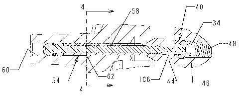
Passage 34 extends between the oFposing ends of piston 20 and
communicates chamber portions 36 and 38 on opposite ends of the piston.
Ball-type check valves 40 and 42 are~ fitted in the ends of passage 34
with valve 40 adjacent chamber portion 36 and valve 42 adjacent chamber
portLon 38. Each valve includes a cylindrical valve seat 44 threaded in
the end of the passage and a ball valve member 46 engaglng the seat
inwardly a short distance from the adjacent end of the piston. Each
ball valve member is exposed to the adj acent chamber portion through the
center of the valve seat. Coil spring 48 is comprised in passage 34 and
normally holds the valve members against the seats to close the valves.
-- ~18~218
Two like elongate plunger assemblies 50 and 52 are mounted in
cylindrical passages 54 and 56 formed in cylinder head 16 and bearing
cap la, respectively. The passages 54 and 56 are co-a~ial with passage
34, as shown in Figures 2 and 3. Each of the passages 54, 56 includes
an inner~ cylindrical portion 58 opening into the adjacent chamber
portion 36, 38 and an outer cylindrical portion 60 opening to one end of
assembly 10. As shown in Figures 3 and 4, the diameter of portion 58 is
slightly less than the diameter of portion 60 so that the two portions
meet at the center of ~ the passage 54, 56 at a circumferential step 62
facing outwardly from the chamber 14.
Each of like plunger assemblies 50, 52 includes an elongate body
64, a cylindrical rolled spring pin 66 surrounding the center of the
body and a stop nut 68 threaded on and secured to one end of the body.
Body 64 includes a cylindrical head 70 at one end and an elongate rod 72
extending from the head inwardly toward chamber 14 to a reduced diameter
poppet end 74. Threads 76 are provided on the end of the rod adjacent
poppet end 74. As illustrated in Figure 5, head 70 includes an outer
cylindrical portion 78 having a sliding fit within outer passage portion
60 and an inner cylindrical portion 80 having a sliding fit in inner
passage portion 58. Portion 80 is smaller than portlon 78. The
portions 78 and 80 are joined by inwardly facing step 82 shown best in
Figure 5. A second inwardly facing step 84 is located at the inner end
of head 70 and rod 72. The outer end of head 70 is provided with an
inward taper 90 and a drive surface 102 located inside the head. Slot
2184218
.~ ,
92 extends across the drive surface. Annular groove 94 is provided in
a head portion 78 and an O ring seal 96 is fitted in the groove.
Spring pin 66 is rolled from a sheet of resilient spring metal, has
a pair of opposed edges 86 extending along the length of the pin and is
5 C-shaped in transverse cross sections. The pin surrounds rod 72 with
one end of the pin engaging step 74 on the head and the other end of the
pin engaging the inner end 88 of nut 68 so that the spring pin is
confined between step 84 and end 88 and cannot move longitudinally on
the body, as illustrated in Figure 5. The nut 68 includes a threaded
10 central bore, and is extended over the poppet end 74 and threaded onto
the threads 7 6 on the end of rod 72 . Spring pin 66 has a relaxed
diameter greater than the diameter of passage portion 58 so that the
spring pin is compressed in the portion, tightly engages the passage
wall and each plunger assembly is held tightly in place on lts
15 respective passage by friction engagement between the outer surface of
the pin and the inner wall of the passage 58. The radially outwardly
exerted spring force of springs 66 and the large area contact between
the outer surfaces of springs and the walls as~ure that both the plunger
assemblies 50 and 52 are held in a desired axial position their
20 passages during normal operation of assembly 10.
Each plunger assembly is mounted on its respective head 16 or cap
18 before the head and cap are mounted on housing 12. Mounting of
assembly 50 in head 16 will be described, it being understood that
assembly 52 is similarIy mounted in cap 18. The body 64 and spring pin
~ ~18~218
66, with stop nut 68 removed, are piloted freely into the outer end of
the passage 54. Head 70 is driven into the passage, compressing the
spring pin as it moves into the inner, reduced diameter passage portion,
until head step 82 seats against passage step 62, as illustrated in
Figure 4. Considerable force may be required to compress the spring as
it is driven into the inner passage portion and to then move the spring
frictionally along the portion. This force is applied to the inner
drive surface 102 on head 70, located inside taper 90. The force may be
sufficiently great to mushroom or deform surface 102 radially outwardly.
0 The taper- 90 assures that outer mushrooming of surface 102 does not
increase the outer diameter of the head sufficiently to cause binding in
the outer passage portion 60. Binding of this type between the head and
the wall of the passage could prevent or make difficult adjustment of
the plunger assembly in the passage.
After the body and spring pin of each assembly have been driven to
the position of Figure 4, the stop nuts 68 are threaded onto threads 76
until ends 88 engage the adjacent ends of the spring pins so that the
spring pins are held against axial movement on the body. During
threading of the nut on the body a screwdriver is extended into the
assembly passage and into seat 92 to hold body 64 against rotation. The
nut is then staked to the end of the rod to prevent unintended
loosening. With plunger assemblies 50 and 52 mounted in passages 54
and 56, the cylinder head and bearing caps are mounted on the ends of
~-- 218~218
body 12 with both plunger asseTnblies 50 and 52 fully extended into the
cavity portions 36, 38 and with steps 82 engaging steps 62.
Extension of the plunger assemblies into the inner portions of
passages 54 and 56 co~press the spring pins so that the spring pins are
resiliently held against the passage walls as shown in Figure 4. The
pins preferably are spaced outwardly from rod 42 to prevent binding
against the rods. The gap 104 between the springs and rods assures
resilient contact against the passage wall despite dimensional
variations in the diameters of the passages, the shape of the pin and
diameter of the rod. The surface-to-surface contact between the pins and
the passage extends substantially around the circumference of the
passage and aLong the length of the plunger assembly between the head
and nut. The spring resilience of the pin biases the pin outwardly
against the passage walL to assure a large area high pressure friction
connection between the pin and wall. The spring pin is held on the
assembly against axial movement between step 84 and end surface 88 o~
nut 68. The large area high pressure friction connections between the
assemblies and the passages assure that after proper set up, the plunger
assemblies are retained in fixed positions in the head and cap 16, 18.
Hydraulic power steering gear assembly, with fully extended plunger
assemblies 50, 52, is installed in the power steering system of roadway
vehicle so that rotation of the steering wheel of the vehicle rotates
input shaft 22 to provide power assisted steering to the front wheels.
The limits of the power steering stroke are then adjusted to assure that
-- 2~84218
during operation of the steering system the front wheels cannot be over
rotated .
After installation of assembly lO in a vehicle power steering
assembly, the steering wheels are elevated or placed on turn plates and
5 a worker turns the steering wheel and connected input shaft between the
full right and left positions. The steering wheel is first rotated to
move piston 20 in one direction until one of the front wheels engages a
wheel stop. The rotation of the steering wheel moves the piston toward
one end of the chamber tQ open the check valve. During further rotation
10 of the steering wheel and final movement of the piston, the end face of
the piston engages the outer end of adjacent nut 68 and pushes the
plunger assembly inwardly along the passage 54, 56 until the wheel stop
prevents further rotation of the front wheels and stops further movement
of the piston.
After setting of the plunger assembly at one end of the chamber 14,
the vehicle steering wheel is rotated in the opposite direction to move
the piston to the other end of the assembly and rotate the steering
wheels to the opposite maximum position against axle stop to thereby
move the extended plunger assembly at the opposite end of the chamber
20 into its respective passage an appropriate distance.
Slots 106 are provided in the outer ends of nuts 68 to permit
hydraulic fluid flowing through passage 34 to flow outwardly past the
nut when the piston engages the nut during initial setup of the plunger
assemblies .
11
~ 2184218
After the plunger assemblies have been adjusted the vehicle wheels
are loaded so that during normal operation the driver is unable to turn
the steerlng~wheel sufficiently to shift the assernblies from thelr
proper positions.
With both plunger assemblies 50 and 52 adjusted as described, the
poppet ends of the assemblies are positioned in the chamber 14 to open
check valves 40 and 42, and relieve pressure across the piston before
the piston travels sufficiently to move the steering wheels into
engagement with the stops. After proper setup adjustment of plunger
assemblies, the large area of high force friction connections between
the assemblies and their respective passages holds the assemblies in
adjusted position in the head 16 and cap 18, thereby assuring that the
gear assembly 10 maintains its adjusted steering stroke.
The spring bias frictional engagement between the plunger
assemblies and the walls of the passages 54 and 56 not only reliably
hold the assemblies in proper position after adjustment and during long
term operation of the gear assembly but also permlt readjustment of the
assemblies in the passages as required, and then hold the assemblies in
place the readjusted positions as before. For ins~ance, the stop
positions for the steering assembly may have to be readjusted in the
event diffeLent size steering tires are fitted on the vehicle or the
extent of rotation of the steering wheels is changed. In that event,
readjustment of the piston stroke is easily accomplished by inserting
a tool in each assembly passage 54, 56 and driving the assemblies to the
12
2184218
fully extended positions where stops 82 engage steps 62. Once the
wheels are raised or placed on turn plates and the assemblies have been
fully extended, the assemblies are moved outwardly in the passages by
rotation of input shaft 22, as previously described, to reposition the
5 assemblies as required. Once repositioned, the large area spring
contacts between the spring pins and inner portions of the passages hold
the assemblies in place. Movement of the plunger assemblies in their
respective passages slides the spring pins along the inner portions of
the passages without injury to the pins, so that repeated adjustment
10 does not alter the ability of the spring pins to hold the assemblies in
place reliably. Adjustment of the positions of the plunger assemblies
is easily performed by a single workman who rotates the vehicle steering
wheel .
The provision of the o rings 96 in heads 70 prevents outward flow
15 of hydraulic fluid through the plunger passages and eliminates the need
for a cap or seal at the outer ends of the passages. Nonetheless, it
may be desirable to seal the ends of the passages to prevent dirt and
debris from collecting in the passages.
On occasion, it may be necessary to bleed air from cylinder chamber
20 14. In order to bleed all air from the cylinder it is necessary to
extend the piston 20 fully to each end of the cylinder. This operation
is easily performed in gear assembly 10 because the plunger assemblies
50 and 52 may be fully retracted into their respective passages 5~ and
13
2184218
56 during bleeding and then may be fully reextended and adjusted to
proper working positions, as previously described.
Plunger assemblies 50 and 52 are manufactured without the
requirement for precision tolerances. Likewise, the plunger assembly
5 passages 54 and 56 need not be manufactured to precision tolerances.
These factors reduce the cost of manufacture of the gear assembly while
providing improved performance over conventional gear assemblies using
poppet valve members which are held in precisely toleranced passages
using pressed fits and deformable crush rings.
While I have illustrated and described a preferred embodiment of
my invention, it is understood that this is capable of modification, and
I therefore do not wish to be limited to the precise details set forth,
but desire to avail myself of such changes and alterations as fall
within the purview of the following claims.
14