Note : Les descriptions sont présentées dans la langue officielle dans laquelle elles ont été soumises.
2t 848~7
.~llL~-19g6 ~19:2~ FROM W.~ RhCE - P~rENT ~EPr. T~ 171a3305~71'3 P.E~
,~ ~
PGTlUS G~ 5 ~ O 2 4 1 7
~7 Rec'd PC~ JUL 1996
FLOW MOD}FICATION D~SVICES FOR k~l~U~~
E~5ISS}ONS FRO~ ~ER~AL ~OC OXI:DIZERS
~a~" Vlll.~ of ~ Tn~nti on
1. Field of th~ Invention
This invention relatss to the use o~ t,d f low
modif ication devices for us~s with Volatile Organi~
0 C ~ ds ~VOC) emission control equipment.
Flow distribution devices can be the key to the
effi~ient operation of chemical processing quipment such
as contactors and reactors, mixers, burners, heat
15 exchangers, ex~rusion dies, and even textile-spinning
chimneys. To obtain optimum distrib~tion, proper
consideration must be given to flow behavior in the
distributor, flo~ conditions upstre~un of thQ distributor,
and flow conditions downser~am of the distributor.
20 Guidelines Eor the design of various types of fluid
distribu~ors are provided in the literature, e.g, see
Chem~al Ens~ineers Handbook, ~ . Perry and C. H
Chilton, eds., ~iEth Edition, McGr~w ~ill, Chapter 5,
ls73, pa~es 47-57.
ZS
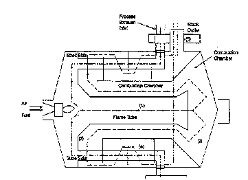
Flow distributors are employed in thermal voc
incineration systems both for thermal energy management
and for ~ontrolling Qmissions~ S~veral different types
o flow distributors may be ur-ed. Examples of possible
30 locations for irstallation of distribution devices, shown
in Figures 1 emd 2, include:
~ i) The Flame q`u`ce ~Location 1): ~ore effi~ient
combustion o~ VOCs is typically obtained by increasing
te~per~a~ure, tur~ulence, a~d the resid~nce tim~ of the
35 ~oCs within the reaction chamber~ Unfortunately,
i~lcreased temperatt:re al~;o ~ccelerates the ther:nal
oxidation reaction l:,et~een nit~cs~en and ox-ygen, thereby
A ~l f ~
JlIL-15-1~96 ~ 2~ FR01~1 W.R. (~RI~E - Pf~TE~IT DEPT. TO 917~13~ 57~ P.~3~
~ 21 8~8~7 -'
-2- 57 R 'd p~;q~ 2 41Jl 71S9
forming undesi~able nitrogen oxide~ that contribute to
environmental problems such as ozone formation and acid
raln Static mixtures, usually characterized by a high
void fraction, may be used to improve mixing within the
5 flame tube. improved mixing will typically enhan~e the
destruction of VCCs and decrease l~ox and CO emissions.
r5ixtures are commercially a~ailable from several
manufacturers including the Static ~ixing Group of Roch
E~ns~ineering Company, Wichita, KS, and Kenics Static
10 ~ixers, ~hF~min~.r, Inc. No~th Andover, ~.
~ ii) Turning Vanes ~I,oca~ion 2 and 3)~ Vanes may be
used to improve velocity distribution and to reduce
friction loss in bends. For i~ miter bend with low
lS velocity flo~s, simple circular arcs can be used. Vanes
o~ special air~oil shapes may be required ~or hig~-
velocity ~lows. ~or a sweep bend, splitter vanes are
used. These vanes are curved vanes extending from ~nd to
end of the bend and dividing the bend into several
~0 parallel channels.
(iii) Perforated Plates and Flow Straighteners
~Location g): These are u3ed for achieving ~low
uniormity by adding sufficient uniform resistance. Flow
25 straighteners ~an include monolithic struct~res or a ~ed
of solids. The degree of flow uniformity achieved via
flow straighteners is related to pressure drop by
relationships discussed in the literature le-g-, see
Perry et al., i~ low straighteners can l~e optimally
30 located in ~he h~:at exchanger section of ~he thermal
oxidation system to maximize heat recovery.
The object o~ the Fresent in~ention is to
incorporate catalytically-active flo~ modi~ication
2 1 8~8~7
WOgs124s90 PCT/US95/02~17
--3 --
devices into thermal oxidation systems so as to achieve
both flow modification and VoC and CO emission
reductions. An additional benefit may be operation of
the combustor at a lower temperature. This could
potentially reduce NOx emissions and permit the use of
lower alloy steels.
The maximum catalytic oxidation conversion is
determined by the mass transfer-limited performance of
the catalyzed flow modification device according to the
relationship
-ln(l-X) = }~
where X is the fractional conversion, km is the external
mass transfer coefficient, S is the total geometric
surface area and Q is the volumetric flow rate of exhaust
gas. Correlations for km as a function of the Reynolds
and Schmidt numbers are available in the literature
(e.g., Fundamentals of Momentum, Heat and Mass Transfer,
John ~iley & Sons, 1976, page 589).
Equation l suggests that the catalytic conversion of
the oxidation system can be increased by increasing the
catalytically-active surface area of the flow
modification device (S~, the external mass transfer
coefficient (km), or by decreasing the flow rate of the
exhau s t ( Q ) .
S may be increased by either increasing the
~eometric surface per unit volume of the device and/or by
increasing the volume of the device. Increasing
geometric surface area per unit volume typicall~ results
in increased pressure drop. Such an option can be
2~ 2 7
wog5/24590 r~,l" ~ l7
--4--
implemented in the case of a Elow straightener.
Increasing the volume of the device is an option in the
case of flow distribution devicesr e.~., mixers or
turning vanes. The coefficient k"~ primarily depends on
the local velocity and the hydraulic radiua of f low. As
discussed above, k,~, is obtained from literature
correlations .
The performance of the device can only approach the
conversion predicted by equation (1) iE the catalytic
layer is highly active under conditions of operation.
High activity may be obtained by the UOEe of noble or base
metal catalysts as practiced ill the art. Another OptiOII
is to fabricate the device using a metal having catalytic
activity. E~xamples of such metals are Cr and Ni-
containing tainless steels. Such steels could also be
alumini~ed to form a surface alloy layer which ia later
activated by chemicals and treated to form a
catalytically active surface.
Catalytic activity can also be increased by placing
the device at a temperature that is high enough to
increase tho catalytic reaction rate but ~IOt high enoug~
to irreversibly deactivate the catalyst or ~tructurally
damage the ~low device. The catalyst could be placed in
the flame tube to light off the oxidation reactions.
Complete oxidation of VOCs can be accomplished either
across the catalyst or by a combination of cAtalyst and
subsequent homogeneous gas phase reactions. The latter
concept is referred to by those in the art as catalytic
combust ion .
2 1 848~7
wo ~s~24ssn 1~"~ q~17
~,
2. Description of the Previously Published Art
Air flow management is a key to the efficient
operation of thermal oxidi2ers for controlling Volatile
Organic Compound (VOC), carbon monoxide (CO) and nitrogen
oxide ~NOx~ emissions. Flow modification devices ;e.g.,
mixers, flow straighteners, flow diverters, etc. ) are
being used in the art to maximize both conversion of VOCs
in the combustion chamber and heat recovery in the
recuperative or regenerative heat exchanger. TWG
possible types of recuperative thermal oxidation systems
conventionally used for VOC destruction are shown in
Figure l and 2.
A conventional thermal oxidizer operates at
temperatures in excess of 1,400~F and Gonverts over ggs6
of the VOCs; however, the exhaust can contain NOX tformed
in the burner) and CO (a product of incomplete
combustion). Environmental regulations are requiring
increasingly stringent controls on VOC, CO and NOX
emissions. For example, European regulations are
requiring the control of VOC levels below 20 mg/Nm~, and
control of CO and NOX levels below 50 mg~Nml.
U.S. Patent 3,gl7,811 teaches fluid management by
static mixers which may be formed of catalyst coated
materials ~col . 2, line 3 ) . The process is broadly
directed to producing a "physiochemical change of (the)
state of interaction between a fluid and a material which
is physiochemically interactive with such fluid". The
mixing device described comprises a conduit which
contains a plurality of curved sheet-like elements
extending longitudinally through the conduit and in which
consecutive elements are curved in opposite directions.
WO~S124lgO 2 1 8~82~ P~
An example given for the use of the device is the removal
of S02 from air using water. It is claimed that the
patented structure provides impro~fed gas-liquid
contacting compared with other conventional materials
~such as ceramic Raschig rlngs) used in packed bed
columns. The patent does not discuss the application of
catalyst-cGated flow modifiers for the gas phase
oxidation of V~Cs from ir1dustrial plant exhausts, the
apparatus does not utilize a thermal oxidizer, nor does
the patent specify the parameters required for efficient
mixing and destruction of the VOCs.
U.S. Patent 4,318,894 is directed at catalytic
purificatiorl of exhaust gases and which teaches the
concept of coating a flow modifying component of a
catalytic purifier with a catalytic mass ~see col 2, lir~e
27 and claim 9, ) . This patent describes al1 apparatus for
the catalytic purification of exhaust gases from
combustion engines of motor vehicles comprising a
customary metal automobile exhaust pipe the dimensions of
which do not vary along the length and which does not
contain any pecial housings or canisters for catalysts.
Further, the exhaust pipe contains flow interrupting
bafEle surfaces which are secured to metal ribbons
mounted at one or ~everal points inside the pipe. The
exhaust pipe is mounted between the e~chaust outlet of the
engine and the muffler and is the sole means for control
of pollutants f rom automobile exhausts . This patent does
not address the special needs of processes for
destruction ~of VGCs emitted from industrial plants, nor
does the apparatus have a thermal burner.
U . S . Patent 5 ,150, 573 relates to a catalyst
arrangementl particularly Eor internal combustion
2 1 84827
wo ss/2~sn PCT/l;Sg~/02417
-- 7--
engines, having a diffusor widening in the flow direction
preceding a honeycomb-like catalyst body and a converger,
narrowing in the flow direction, following t~le catalyst
body. A flow guide i5 placed in between the diffusor and
the converger and the surfaces of the flow guide are
coated with catalytic active material (col. 4, line 25) .
The device of the present invention does not include
converger or diffusor components and is, as will be
discussed later, particularly suited for VOC control.
U.S. Patent 5,209,062, is directed to a diesel
engine having in its exhaust manifold, a static mixer
coated with catalytic material (col. 3, line 17). In
addition, nozzles are provided in an annular chamber
between the static mixer and the exhaust manifold in
order to introduce a reducing agent into the f low of
exhaust gas prior to entry into the static mixer. This
apparatus is particularly suited for diesel engine
applications and, due to the compositional requirements
of the exhausts, is not suitable for VOC destruction.
U.S. Patent 4,725,411 discusses a fluid treating
device for carrying out chemical and/or physical
reactions in a flowing stream in contact with a
stationary corrugated thin metal member. The converter
comprises a housing and a fluid inlet and outlet,
indicating that the device is a stand-alone system for
conducting physical and/or chemical reactions. The
converter contains a metallic foil having zig-zag
corrugations which is folded back and forth on itself
into the converter as an accordion . Fluid f lows through
the spaces between alternate layers of foil. Catalytic
washcoats may also be coated on the metallic foil and the
device is useful as a catalvtic converter. The device is
.
2 1 ~2~
Wo 9~4124s9(1 P~T/US9~2-~17
--8--
also proposed for use as a particulate trap, especially
for diesel ~llgine applications. The above device is not
proposed for use as an i~ltegral part of thermal VOC
oxidizer system nor is its proposed use for fluid flow
modification.
3. Objects of the Invention
It is an object of this invention to improve the
performance of an emis~ion control device such as a
thermal oxidizer by using modification devices for
reducing temperature and flow maldistribution within the
devi ce .
It is a further object o~ this invention to use flow
modification devices that reduce emissions of pollutants
such as VOCç~, CO and NOX from thermal oxidizer e~hausts.
The materials of construction for these devices wil~.
withstand the local operating conditions and reduce CO
and VOC emissions.
It is a further object of this invention to use flow
modification devices that are coated with a catalyticall~
active layer. Catalytic ingredients can include noble
metal or base metal oxidea diapersed on a high surface
area mixed oxide support.
It is a further object of this invention to properly
select and position these f low modif ication devices
within the thermal oxidizer to reduce stack emi~sions of
VOCs and CO.
These and further objects will become apparent as
the descript~Lon of the invention proceeds.
2 1 84827
~ W0 9sl24s90 r~ '7417
g
Summary of the Invention
Improved performance of thermal oxidizers is
obtained by incorporating catalytically-active flow
modification devices into the thermal oxidizer apparatus.
Examples of these flow modification devices include, but
are not limited to, turning vanes, f low mixers, f low
straighteners, and flow diverters. The flow modifiers of
the present invention reduce emissions of residual VOC
and CO in the burner and/or combustion chamber, or in
subsequent heat exchange equipment.
The apparatus for thermally oxidizing waste 5ases
with reduced emissions has a gas inlet to which the waste
gas stream to be oxidized is supplied. The gas inlet is
connected to a reactor for thermally oxidizing the waste
gas stream. The reactor preferably has either a pre-mix
burner or a nozzle-mix burner to t~lermal~y oxidize the
waste gas stream. The reactor is connected to an exhaust
outlet for releasing the oxidized gas from the apparatus.
Positioned between the gas inlet and the exhaust outlet
are catalyzed surface devices such as the flow
modification devices discussed above w~lich contact the
waste gas and further oxidizing the waste gas. In the
preferred embodiment where the catalyzed surface area is
S and the volumetric flow rate of waste gas passing
through the device is Q, the ratio of Q/S is at least
0.025 ft/sec.
The method for reducing the emissions of VOC
containing waste gases from a thermal oxidizer involves
treating the waste gas in a thermal reactor and
additionally contacting the waste gas either before, in,
or after the thermal reactor with a catalyzed surface
2 ~
Wo 9~24~90 PCrIUS95102417
-10-
device in the gas stream within the thermal oxidizer
apparatus. The catalyzed surface device has a catal.yzed
surface whic~l contacts the waste gas and further oY~idizes
the waste gas.
srief Des~ tion of the ~awinq
Fiyure l is a schematic drawing of an annular
thermal oxidizer containing an annular recuperat ive heat
exchanger.
Figure ~ is a schematic drawing of an annular
thermal oxidizer containing a non-annular recuperative
heat exchanger. Figures l and 2 are illustrious of
thermal oxidizers that may contain the flow modification
devices of this invention.
Figure 3 is a photograph of a f low mixer device .
Des~ri~tion of the Preferred Embodiments
The no~elty of the present invention i5 illustrated
for a mixer and flow straightener. Such devices may be
placed prior to or after the recuperative heat exchanger.
For example, the flow straightener may comprise a
corrugated metal foil that is folded back on itself to
form a monc lith structure . A pressure drop of 1 to 5 " of
water column acrosP the device is generally su~ficient to
obtain unifor~ flow through the heat exchanger.
Incorporation of a catalytically-active flow
modifier can result in the following two advantages.
First, the average combustion chamber temperature may be
reduced fr~;D abo~e 1,400 to 700-1,000F, resulting in
2 1 84827
WO 95/24~gO P~/USgS/02~17
lower NOX emissions from the burner. Secondary economic
benefits may be (a~ the use of lower-grade stainless
steels in the combustion chamber (i.e., lower capital
costs), and (b) lower fuel usage (i.e., lower operating
costs) .
Second, the VOC may be converted to CO in the
combustion chamber. CO and unconverted VOCs are then
converted to CO2 across the flow straightening device.
The exothermic heat of reaction liberated in the burner
zone by the conversion of the VOC to CO is 50 to 6596 of
the total heat that would be liberated in the conversion
of the VOC to CO2 (which is the preferred product of
reaction in thermal oxidizers) . As stated in the f irst
advantage above, conversion to CO may reduce the peak
temperature in the burner f lame thereby reducing NOX
formation. Further, heat liberated in the flow
straightener from conversion of CO to CO2 may be more
efficiently recovered by positioning the flow
straightener at an optimal location prior to or in the
heat exchanger.
The overall impact of the invention is that the
thermal oxidizer-based emission control system will have
lower emissions control system will have lower emissions
of VOC, CO and NOX for a given operating temperature.
Thermal burners are used in VOC oxidation equipment
to increase the average temperature of the VOC-laden
exhaust. The main purpose of the burner is to ~acilitate
thermal oxidation of VOCs. Thermal oxidation can also
occur in other types of apparatus, e.q., stationary and
mobile (automobile or diesel ) engines . The purpose of
co~nbustion in these devices, however, is to generate
reliable power and not to reduce pollutant emissions.
JlJL-15-1596 ~ 27 FP~011 LJ.R. GRRI:.E - PflTE~T D~EPT. TO 9171~331a57719 P.08
2 1 84827
-12- P~UU~ ) I C2.417
L ~ 3
Burners used in oxidation equipm~nt are typically
fired by ra~q natural gas. ~h~re are several types of
buzner designs used in tha industry. IrwO i~ortant
~lasses o~ burners are la) premix bùrners, and (b) nozzle
S burr,ers.
Premix burners burn by hydroxylation and are used
for natural-draft applications ~u1d for ~orced-drat
applicacioGs when controlled exhaust conditions are
required. Saveral high velocity burners, though not
strictly premix burners, produce temperatures and mixing
similar eO premix burnerg ~e.g, see Chemical Engi~eers
Handbook, 3~. ~. Perry and C. H. Chilton, eds., Fifth
Edition, McGraw ~iill, Chapter S, 1973, pages 4~-57i. In
premix burners, the rate of ~lame propagation :nust be
e~d~:d to assure that ignition cannot travel back into
the burner. Flow mixing devices can sometimes be used to
stabilize the ~lame and prevent t~e flame fro~ traveling
into the burner.
Nozzle-mix burners mix air and gas at the burner
tile. ~he burner may be a standard or~ed-dra~t register
with the gas emitted f~rom holes drilled in the end of a
supp1y pipe. While ea~.y to build, the large holes in
~5 these burners can ~ause gas mixing problems these
burners requently produce a luminous gas fla~r.e. Small-
diameter pipe can be inserted at the center o the burner
or large-dia~neter rings can extend to the outside o the
burner tile. These rings c~3n l~fie very s;nall holes ar~d
give better dispersion o gas in the air, though they can
plug up easil~. Burners can alterr~atively hav~ spiders
located ir. the burner inlet and through whi~h gas is
emitted i~ all the several radial arms. The spider is
drilled to emit gas rocn the sides o~ the bars to pro~ide
a reaction ~rom emission o~ the high presRure gas,
causing the spider to turn. The spider can be a~tached
~M~
TU~-15-1~96 e~Y:Z'~ FRI]1`1 IAI.R. ~ 'E - P~:lrE~JT DEPr. TO ~17133305771Y P.~9
~ 2~ 84~27 ~ S ~ J ~
-13- 57~ dP~T~ 5 J!J~ ~Q9S
to a fan so that orced dra~t is provided by the moverne~t
of the spider. The spider a~ . t provid~s high
euzbu}ence for close regulation of excess air.
S The f low modif ication devices of this invention may
be placed a~ter the ~urner at the various locatio~7~ 1, 2,
3, 4, and 5 shown in Figures ( 1~ and ~ 2 ) . '~ c are
provided o~ mixing devices ~nd ~ow straisrhteners. Th~
materials o~ ~onstruction ~an include suitable ¢tainless
steels te.g., contair~ g Cr) or steels ~oaced wieh a
catal~tic~lly-a~tive layer. Catalysts used ~an include
no~le metals (e.g., Pd, Pt, Rh, Re, et~ . ) and bas~ metal
oxides (e.g., Cr, Cu, V, W, Mo, Mn perovskites, zeolites,
et~ . ) either supported or in combination with high
sur~a~e area inorganic oxides (e.g., alumina, silicas,
clays, etc. ) and binders ~e .g., aluminum chlorohydrol,
sili~a and alumina sols, acid-peptized mixed oxi.des,
et~
~aving described the basic aspects o~ the inver~tion,
the ~ollo~ing e~xamples are ~iven to illustrate spe~
o~; ts thereo~.
,F ~R~le 1
A 33 . 8~ diameter, 7 9~ deep mixer made of a lean
austenitic heat resistant alloy rA ZS3~A manu:ea~tured in
Sweden by Avest3 Corporation and ha~ring a nominal
R 1 ~omposition o~
E:letm~at 9~ ComDosition
Nickel 11
Chromium 2 1
Manganese o . 6
Sili~on 1.7
Carbon o . o 8
Nitrogen 0.17
C~rium 0 . 0
Iron 65
,
W0 9~l2~S90 2 t 8 4 ~ 2 7 ~ u~ 7
-14-
was installed at location 1 in a 33.8" diameter flame
tube of 21,772 scfm thermal oxidizer similar to that
shown in Figure 1. The geometry of the 3 rows of turning
vanes in the mixer is shown in Figure 3. The geometric
surface area~ of the mixing device ~S) was 4g3 ft3. Thus,
according t~Equation 1, the ratio of Q~S is 0.82 ft~sec.
The mixer was installed into the flame tube and the
following results were observed:
Il) Flame tube temperature stratification was
reduced from greater than 250F without the mixer to less
than 40F with the mixer. The pressure drop acros3 the
mixer was 10l' wa~er column at full flow.
12) Pr~ior to mixer installation, CO emissions
oscillated between 15~ and 320 ppmv wi~h several. CO
spikes of over 400 ppmv. These variations were believed
due to (1) above, inadequate burner control, and damper
f low transients . Burner controller tunins together with
installation of the mixer reduced CO emissions to the 40
to 80 ppm range during "run" mode, and less than 300 ppmv
during the damper flow transients.
Examl~le 2
A flow straightening device with cross-sectional
area of approximately 7.4 ft2 and 3 5" deep was ins~.alled
at location (3~ in a g, 500 scfm thermal oxidizer similar
to that shown in Figure 2 . The structure of the f low
straightener was similar to that discussed in U. S . Patent
4, 725, 411. The surface of the flow straightener was
coated with a layer of catalyst ,-,,n~;n;ng noble metals
irnpregnated on a 26~ ceria, 749~ stabilized alumina
support. The loading of n~ble metals was 40 g~ft3 of
catalyst, with a Pt to Pd ratio of 3. The geometric
~184~7
wo 95l24590 PCTiUS95l02417
- 15-
surface area of the mixing device was 1430 ft2. Thus,
according to Equation 1, the ratio of O/S is 0.11 ft/sec.
The flow straightener was installed and the
performance of the thermal oxidizer was monitored as a
function of heat input for a 9, 500 scfm exhaust flow
c~n~;n;n~ heptane VOC (expressed at 3,000 pp~ of C,) .
The concentration of VOC, CO and NOx was monitored before
t~le burner, after the burner (or before the flow
straightener), and after the flow straightener as shown
in Table 1. As shown in Table 1, significant reductions
in the levels of CO and VOC are achieved by the
catalytically-active flow straightener.
2~ 848~7
wo 9~f_~90 1~ r~ ~J~ ?.J17
~ o G? 1~ ~` ~D N e~ r~ 0 01 01 0
O .
~ O IL? N N ~ ~ ~ O? ~ ~1
g 2 ~ ~ ~ o~ IL? ~" i i i
a~ B ~ 0 oO 0 00 0 N N ~
O ~ 1-- G? ~ ~ N ~ ~ '--
~) -- Q t~ t N O? U~ ~ 'r N ~ 't
1-- --
,,~, > N IL? 0 ~ 0 Ul 0? `-- 2 N O
~X
E ~ r_ U~ u~ ~ o o o o o ~,
-- E ~ 0 ~ ~ 0 ~ 2 2 ~ ' ~ ~ ~
m ~
o ? OE:l n O ~ 0 o~ o ~ ~ cq ._ ~?
-- > Q ~I N Cl~ N ~1 <.~ ~ ~ ~ t~
C~
N :~:
n o u~ O
21 84~27
W09sl24s90 r.l",.,. .~o2~l7
1 7-
The reduction of CO and VOC across the
catalytically-active flow straightener is quantified in
Table 2 for a range of inlet temperatures. A shown in
Table 2 for the first 8 runs in Table 1, reduction of CO
in the 83 to 98 . 5% range and reduction of VOCs in the 70
to 95 . 5~ range are obtained from the burner outlet
concentrations .
Table 2
Flow Straightener Catalytic Performance
(Flow = 9950 scfm; VOC = 3000 ppm heptane as Cl)
Inlet Temperature Conversion (96)
( F ) VOC CO
598 70 . 4 83 . 3
699 81 . 1 94 . 9
800 87.4 93.2
899 87 . 0 90 . 2
996 87 . 0 91 . 2
1096 91 . 3 94 . 2
1200 92 . 3 97 . 9
1250 85 . 0 96 . 1
1300 95 . 5 98 . 5
It is understood that the foregoing detailed
description is given merely by way of illustration and
that many variations may be made therein without
departing from the spirit of this invention.