Sélection de la langue

Search

Sommaire du brevet 2185080 

Énoncé de désistement de responsabilité concernant l'information provenant de tiers

Une partie des informations de ce site Web a été fournie par des sources externes. Le gouvernement du Canada n'assume aucune responsabilité concernant la précision, l'actualité ou la fiabilité des informations fournies par les sources externes. Les utilisateurs qui désirent employer cette information devraient consulter directement la source des informations. Le contenu fourni par les sources externes n'est pas assujetti aux exigences sur les langues officielles, la protection des renseignements personnels et l'accessibilité.

Disponibilité de l'Abrégé et des Revendications

L'apparition de différences dans le texte et l'image des Revendications et de l'Abrégé dépend du moment auquel le document est publié. Les textes des Revendications et de l'Abrégé sont affichés :

  • lorsque la demande peut être examinée par le public;
  • lorsque le brevet est émis (délivrance).
(12) Demande de brevet: (11) CA 2185080
(54) Titre français: PORTE A ENROULEMENT VERTICAL
(54) Titre anglais: ROLL UP DOOR
Statut: Réputée abandonnée et au-delà du délai pour le rétablissement - en attente de la réponse à l’avis de communication rejetée
Données bibliographiques
(51) Classification internationale des brevets (CIB):
  • E06B 3/48 (2006.01)
  • B60J 5/12 (2006.01)
  • E05D 1/02 (2006.01)
  • E05D 15/24 (2006.01)
  • E05F 15/668 (2015.01)
(72) Inventeurs :
  • MARTIN, JOHN C. (Canada)
(73) Titulaires :
  • DIESEL EQUIPMENT LIMITED
(71) Demandeurs :
  • DIESEL EQUIPMENT LIMITED (Canada)
(74) Agent: SMART & BIGGAR LP
(74) Co-agent:
(45) Délivré:
(22) Date de dépôt: 1996-09-09
(41) Mise à la disponibilité du public: 1998-03-10
Licence disponible: S.O.
Cédé au domaine public: S.O.
(25) Langue des documents déposés: Anglais

Traité de coopération en matière de brevets (PCT): Non

(30) Données de priorité de la demande: S.O.

Abrégés

Abrégé français

Cette invention concerne une porte à enroulement vertical destinée à fermer l'arrière d'une caisse de camion, ladite porte étant composée d'une pluralité de lattes jointives sur la face extérieure desquelles est collée une feuille souple mince. De l'autre côté, chaque paire de lattes adjacentes est reliée par un ruban souple. Chacune des lattes porte un galet à ses deux extrémités qui circule dans un chemin de roulement ayant la forme générale d'un L inversé. Grâce à cette disposition, les lattes peuvent s'incliner lorsque les galets correspondants passent de la partie verticale à la partie horizontale du chemin de roulement, les courroies se plissant à la manière d'un soufflet et permettant à la feuille de revêtement extérieur de plier également.


Abrégé anglais


A roll up door which may be used in the back of a van
body comprises a plurality of panels arranged edge-to-edge with
a thin flexible sheet glued to the outside face of the panels
and a flexible belt attached to each pair of adjacent panels at
the rear face of these panels. A roller extends from each end
of each panel and is received by a generally inverted L-shaped
guide track. With this arrangement, the panels may cant while
moving from the vertical to the horizontal leg of the guide
channels by virtue of the belts which hinge and collapse
allowing the outer sheet to bend as well.

Revendications

Note : Les revendications sont présentées dans la langue officielle dans laquelle elles ont été soumises.


THE EMBODIMENTS OF THE INVENTION IN WHICH AN EXCLUSIVE
PROPERTY OR PRIVILEGE IS CLAIMED ARE DEFINED AS FOLLOWS.
1. A roll up door, comprising:
- a plurality of panels in spaced edge-to-edge relation;
- a flexible sheet having a face which is adjacent one face of
each of said panels, said sheet joined to each of said panels;
- flexible means joined to each pair of adjacent panels.
2. The door of claim 1 wherein said flexible means is adjacent
an opposite face of each of said panels.
3. The door of claim 2 wherein said flexible means comprises a
belt joined to each pair of adjacent panels.
4. The door of claim 3 wherein said sheet comprises an outer
surface of said door.
5. The door of claim 4 wherein each panel is radiused from said
one face of the panel to a bottom edge of the panel and from
said one face of the panel to a top edge of the panel.
6. The door of claim 5 including, for each panel of said
panels, a backing panel joined to said opposite face of said
each panel.

7. A roll up door system, comprising:
- a roll up door having a plurality of panels in spaced
edge-to-edge relation; a flexible sheet having a face which is
adjacent an outer face of each of said panels, said sheet
joined to each of said panels; and a flexible means adjacent an
opposite, inner, face of each of said panels and joined to each
pair of adjacent panels;
- a pair of guide channels; and
- a roller extending from each end of each of said panels, with
rollers extending from a given end of said panels being
received within one of said guide channels.
8. The system of claim 7 including an operator controlled
linearly moveable support and a link arm extending from said
support and pivotally joined to said door proximate a top of
said door.
9. The system of claim 8 wherein each of said rollers have a
support shaft and wherein said link arm is pivotally joined to
a support shaft of one of said rollers.
10. The system of claim 9 wherein said linearly moveable
support comprises a block carried above said door by an endless
chain and including a motor for driving said endless chain.
11. The system of claim 7 wherein each panel is radiused from
said outside face of the panel to a bottom edge of the panel
- 8 -

and from said outside face of the panel to a top edge of the
panel.
12. The system of claim 10 wherein said endless chain is
proximate one of said guide channels and including a further
endless chain proximate another of said guide channels, said
further endless chain carrying a block from which a further
link arm extends and is pivotally mounted to a support shaft of
another of said rollers.
13. The system of claim 8 wherein said flexible means comprises
a flexible belt joined to each pair of adjacent panels.
14. The system of claim 10 wherein said endless chain is
supported at one end by a spring whereby said block may be
driven to a position whereat said link arm rotates overcentre
to lock said door in a closed position.
15. The system of claim 10 wherein said endless chain comprises
a sprocket, said sprocket having a nut fixed thereto for manual
driving of said chain.
- 9 -

Description

Note : Les descriptions sont présentées dans la langue officielle dans laquelle elles ont été soumises.

2~1 85~8~
ROLL UP DOOR
Background of the Inventlon
1. Fleld of the Inventlon
Thls lnventlon relates to a roll up door and a roll
up door system.
2. Descrlption of the Related Art
U.S. patent No. 4,860,813 to Ballyns dlscloses a roll
up door for the back of a van body. The door comprlses a
plurality of panels ~oined together by hlnges. A guide track
ls posltloned at elther end of the door and rollers extending
from the hinges are recelved by the gulde tracks. The door is
manually operated and a counterbalancing sprlng mechanlsm
attached proxlmate the top of the door moderates the closlng of
the door.
A dlfflculty wlth a roll up door of the type
descrlbed ls that a load ln a van could shlft against the door
and interfere with the hinges maklng openlng of the door
dlfflcult. Furthermore, the outslde corners of the panels of
such a door typlcally degrade wlth tlme and dlrt may lodge
between ad~acent panels. For these reasons, the appearance of
the door becomes less appeallng wlth tlme.
Thls lnventlon seeks to overcome drawbacks assoclated
wlth known roll up doors.
02547-256/RDF:bw:tm

21 85080
summarY of the Invention
In accordance with the present invention, there is
provided a roll up door, comprising a plurality of panels in
spaced edge-to-edge relatlon; a flexible sheet having a face
5which ls ad~acent one face of each of sald panels, sald sheet
jolned to each of sald panels; flexlble means ~olned to each
palr of adiacent panels.
Brlef Descrlption of the Drawinqs
In the figures which illustrate an example embodiment
10of the inventlon,
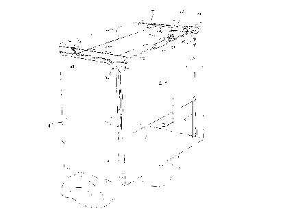
figure 1 is a simplified perspective view of a van
equipped with a roll up door system made in accordance with
this invention,
figure 2 is a cross-sectional view along the llnes
15II-II of figure 1,
figure 3 is a back view of a portion of the roll up
door shown in figure 1,
figure 4 ls a cross-sectional view of the roll up
door of flgure 2 shown ln a hlnged posltion, and
20figure 5 is a schematic side vlew of a portion of a
door control mechanlsm.
Detailed DescriPtion of the Preferred Embodiments
Turning to figure 1, a roll up door 10 made ln
accordance with thls lnventlon ls slldably mounted to generally
25lnverted L-shaped guide channels 12 and 14 by rollers 16 which
extend from elther end of the door and are recelved by the
02547-256/RDF:bw:tm

2 1 85080
gulde channels. The gulde channels are mounted at the back of
a van body shown ln phantom at 18.
Turnlng to flgure 2, it will be seen that the roll up
door 10 comprlses a plurallty of panels 20 ln spaced edge-to-
S edge relatlon. Referencing figure 3 as well as figure 2, eachpanel 20 ls ln the form of a rectangular frame wlth a top frame
member 22, a bottom frame member 24 and end frame members 26
and 28. A metal web 30 ls mounted to each of the end members
and supports a roller 16. The frame members of each panel 20
may be made of lamlnated wood.
A thin flexible sheet 40 (shown in figure 2 but not
ln figure 3) has an lnslde face 42 whlch is posltloned ad~acent
the outslde faces 32 of the panels 20 and ls glued thereto.
The flexlble sheet 40 may be made of thln woven FIBERGLASSTM.
A flexible belt 50 brldges each palr of ad~acent
panels and ls ~olned to the lnner faces 34 of the panels. Each
belt 50 may be manufactured as a woven textlle rlbbon.
Referrlng solely to flgure 2, a backlng panel 60 ls ~olned to
the lnslde face 34 of each panel. Preferably, each backlng
panel ls stapled to a panel 20 through belts 50 so that the
backlng panel holds the belts ln place. The backing panel
closes the central openlng between panel frame members 22, 24,
26, and 28.
Each panel ls radlused at 36 from the outside face 32
of the panel to the top edge 37 of the panel and at 38 from the
outslde edge 32 of the panel to the bottom edge 39 of the
panel.
As lllustrated ln flgure 4, roll up door 10 may be
02547-256/RDF bw:tm

2 1 85080
hinged at a belt 50 such that the belt acts as an lnner hlnge
and the flexlble sheet 40 as an outer hlnge. It wlll be noted
from flgure 4 that the belt 50 collapses as the panel
thereabove hlnges from a vertlcal posltlon.
Returning to flgure 1, the roll up mechanlsm for door
10 comprlses two endless chalns 66, 68 located above door 10,
each chaln supportlng a chaln block 70, 72, respectlvely. An
electrlc motor 76 ls coupled by shafts 78 and 80 to sprockets
82 and 84, respectlvely, for drlvlng the endless chalns 66, 68
ln order to llnearly move the chaln blocks 70, 72. A llnk arm
88 extends from each chaln block 70, 72 and termlnates ln an
eye 89 (flgure 5) by way of whlch the llnk arm ls plvotally
jolned to the support shaft 17 (flgure 3) of the roller 16 most
proxlmate at the top edge 90 of door 10. A portlon of shaft 80
ls threaded and supports a worm 92 wlth a flnger whlch extends
between llmlt swltches 94a, 94b. The llmlt swltches are
connected to a control lnput of motor 76. Through a further
control lnput (not shown) an operator may actlvate motor 76 ln
a forward or reverse dlrectlon.
In operatlon, an operator may actlvate motor 76 to
move endless chaln 66, 68 so that blocks 70, 72 translate
toward the front of the van body 18. Thls ralses door 10.
Referenclng flgure 4 as well as flgure 1, as the rollers 16 of
a panel 20 reach the curved portlon 96 of the gulde tracks 12
and 14, the panel ls gulded from a vertlcal to a horlzontal
orlentatlon. As thls occurs, the panel wlll hlnge wlth respect
to the next ad~acent panel beneath lt at the belt 50 between
the panels. When the door reaches lts fully up posltlon, the
02547-256/RDF:bw:tm

2 1 8~
flnger of worm 92 abuts limlt switch 94b which sends a control
signal to motor 76 in order to stop same. To close the door,
the operator activates motor 76 to rotate in the opposite
direction. This causes blocks 70, 72 to translate toward the
rear of the van body 18. In so doing, the link arms 88 push
the rollers 16 to which they are plvotally ~olned causlng the
door to descend. When the door reaches its closed positlon,
the finger of worm 92 abuts limit switch 94a which shuts off
motor 76.
Since outer sheet 40 is contlnuous, it provides a
smooth clean line appearance to the roll up door and is readily
adapted for painting. Also, since the space between each pair
of ad~acent panels 20 ls closed by the sheet 40 and a backlng
belt 50, no dlrt may enter thls space and, further, the top
bottom edges of the panels 20 are protected from other
degrading influences of the environment.
It will be apparent that the roll up door 10 could be
raised even if a load abutted the rear of the door because the
load would not catch on a the belts 50 nor any other portion of
the door.
Turning now to figure 5 whlch illustrates an
enhancement for the lnventlon, the forward sprocket 98 of
endless chaln 66 may be attached to the van body by sprlng 100.
Wlth thls enhancement, the llmlt swltch 94a may be posltloned
so that the chaln 66 continues to translate chain block 70
until the block assumes the position illustrated in figure 5
whereat link arm 88 has rotated overcentre. Endless chain 68
would be similarly equipped. The driving of the link arms 88
02547-256/RDF:bw:tm

- 21~D~
to an overcentre positlon provides a lock for door 10 in the
closed posltlon.
Sprocket 82 may be provlded with hex nut end 102. A
(lockable) openlng ln the rear portlon of the van body may then
be provlded so that door 10 could be manually ralsed should
motor 76 fall by flrst openlng the lockable openlng and then
lnserting an appropriate hex wrench to manually rotate the
sprocket wheel 82.
Other modlfications wlll be apparent to those skllled
ln the art and, therefore, the inventlon ls deflned ln the
clalms.
02547-256/RDF:bw:tm

Dessin représentatif
Une figure unique qui représente un dessin illustrant l'invention.
États administratifs

2024-08-01 : Dans le cadre de la transition vers les Brevets de nouvelle génération (BNG), la base de données sur les brevets canadiens (BDBC) contient désormais un Historique d'événement plus détaillé, qui reproduit le Journal des événements de notre nouvelle solution interne.

Veuillez noter que les événements débutant par « Inactive : » se réfèrent à des événements qui ne sont plus utilisés dans notre nouvelle solution interne.

Pour une meilleure compréhension de l'état de la demande ou brevet qui figure sur cette page, la rubrique Mise en garde , et les descriptions de Brevet , Historique d'événement , Taxes périodiques et Historique des paiements devraient être consultées.

Historique d'événement

Description Date
Inactive : CIB désactivée 2015-01-24
Inactive : CIB expirée 2015-01-01
Inactive : CIB attribuée 2015-01-01
Inactive : CIB de MCD 2006-03-12
Le délai pour l'annulation est expiré 2000-09-11
Demande non rétablie avant l'échéance 2000-09-11
Inactive : Page couverture publiée 1999-09-30
Réputée abandonnée - omission de répondre à un avis sur les taxes pour le maintien en état 1999-09-09
Demande publiée (accessible au public) 1998-03-10

Historique d'abandonnement

Date d'abandonnement Raison Date de rétablissement
1999-09-09

Taxes périodiques

Le dernier paiement a été reçu le 1998-09-08

Avis : Si le paiement en totalité n'a pas été reçu au plus tard à la date indiquée, une taxe supplémentaire peut être imposée, soit une des taxes suivantes :

  • taxe de rétablissement ;
  • taxe pour paiement en souffrance ; ou
  • taxe additionnelle pour le renversement d'une péremption réputée.

Veuillez vous référer à la page web des taxes sur les brevets de l'OPIC pour voir tous les montants actuels des taxes.

Historique des taxes

Type de taxes Anniversaire Échéance Date payée
TM (demande, 2e anniv.) - générale 02 1998-09-09 1998-09-08
Titulaires au dossier

Les titulaires actuels et antérieures au dossier sont affichés en ordre alphabétique.

Titulaires actuels au dossier
DIESEL EQUIPMENT LIMITED
Titulaires antérieures au dossier
JOHN C. MARTIN
Les propriétaires antérieurs qui ne figurent pas dans la liste des « Propriétaires au dossier » apparaîtront dans d'autres documents au dossier.
Documents

Pour visionner les fichiers sélectionnés, entrer le code reCAPTCHA :


Pour visualiser une image, cliquer sur un lien dans la colonne description du document. Pour télécharger l'image (les images), cliquer l'une ou plusieurs cases à cocher dans la première colonne et ensuite cliquer sur le bouton "Télécharger sélection en format PDF (archive Zip)" ou le bouton "Télécharger sélection (en un fichier PDF fusionné)".

Liste des documents de brevet publiés et non publiés sur la BDBC .

Si vous avez des difficultés à accéder au contenu, veuillez communiquer avec le Centre de services à la clientèle au 1-866-997-1936, ou envoyer un courriel au Centre de service à la clientèle de l'OPIC.


Description du
Document 
Date
(aaaa-mm-jj) 
Nombre de pages   Taille de l'image (Ko) 
Dessins 1996-12-13 3 58
Page couverture 1996-12-13 1 14
Abrégé 1996-12-13 1 17
Description 1996-12-13 6 198
Revendications 1996-12-13 3 84
Page couverture 1998-03-20 1 44
Page couverture 1999-09-29 1 44
Dessin représentatif 1998-03-20 1 9
Rappel de taxe de maintien due 1998-05-12 1 111
Courtoisie - Lettre d'abandon (taxe de maintien en état) 1999-10-07 1 184