Note : Les descriptions sont présentées dans la langue officielle dans laquelle elles ont été soumises.
21 85280
~.
~LQC~ Y~ qs~
DEVICE AND MEl~IOD POR IDENTIFYING A
NUMBER OF INDUCTIVE LOADS IN PARALLEL
TECHNICAL FIELD
Generally, the present invention resides in the art of dispensing devices, sometimes
known as guns, gun modules or dispensing modules, used to dispense fluids, such as liquid
adhesive, sealants or cauLks. More particularly, the present invention det~rmin~s how many
dispensing devices and associated solenoids are connected to a dispensing gun driver.
Specifically, the present invention is directed toward a device for identifying the number
of solenoids, and their representative parallel inductive loads, cormected to the dispensing
gun device so as to generate and adjust a driving current used to actuate the solenoids.
BACKGROUND ART
It is known in the park~ging industry to provide dispensing devices that dispense
liquid adhesive on park~ging m~t~ri~l~ in spots or any other desired pattern, such as a
swirl, a spray, a plurality of beads, drops or droplets. The park~ging m~tPri~l is then
folded in a predet~-rmin~d manner so that the dispensed adhesive comes in contact with
mating portions of the p~k~gina material to form the desired container or package. These
di~cllsillg devices are also employed to dispense adhesives on substrates, woven and non-
woven materials and product assemblies. Due to the high speed nature of this assembly
process, ~i~p~"~ g devices have been developed using electrical control systems which are
also known as gun drivers.
Known dispensing devices include a valve-type system cont~ining a plunger (also
known as an armature or valve needle) received within an orifice, wherein a solenoid is
employed to control the movement of the plunger from a closed position to a dispensing
position and back again to a closed position, such as set forth in U.S. Patent 5,375,738, the
disclosure thereof is illco~oldL~d herein by reference, and which is owned by the assignee
of this invention.
Gun drivers have been developed employing electric circuit controls to enhance the
operation of the dispensing device. ~any factors contribute to the efficient operation of
such a dispensing device inrl~ ing, but not limited to, the viscosity of thë adhesive to be
applied, the heat ~ dted by the Ir~ e and intl~lct~n~e of the solenoid, the temperature
21 85280
.
of the fluid or adhesive to be applied, the desired pattern of the adhesive and the number
of solenoids connected to the control device. To insure the proper operation of the
di~ensillg device or devices, it is illlpoll~lL that the plunger quickly open and quickly close
the orifice when desired. To achieve this, it is required that the solenoid receive a fast pull-
S in current that quickly opens the plunger from the orifice at the beginning of the dispensingcycle, a minim~l holding current which holds the plunger in an open position while
minimi7ing the amount of heat buildup in the solenoid coil during dispensing, and a fast
11ic~ip~tir)n of current from the solenoid coil so that the plunger is quickly closed upon the
orifice at the end of the dis~!ensi~lg cycle. U.S. Patent No. 4,453,652, which is assigned
10 to the ~c~ignee of this invention, describes a method of reducing the current flow through
a coil once the plunger has moved to its open position.
It is ~lesell~ly known to supply current to multiple dispensing mod~ s from a single
current source. In order to p~opelly control the operation of these multiple dispensing
modules, it is required that an operator place switches in predett-rrnin~d positions or insert
15 or remove physical jumper connections between the solenoids so that they operate in the
desired sequence. Several problems arise when the afolt;~l,e.l~ioned switches or physical
jumper connections are not properly implement~ For example, if not enough current is
supplied to the solenoids, the required pull-in current value may not be attained so that the
solenoids remain closed or are delayed in their opening. As such, the desired dispensing
20 pattern is not obtained. It is also possible that too much current could be supplied to a
solenoid so that the solenoid or plunger assembly itself is damaged, thereby causing
downtime to the m~mlf~rtnrin~ process as the solenoid or dispensing device is replaced.
It will also be appreciated that current dispensing devices do not allow for the easy
drlr~ ",i" ~ n of whether a solenoid is operating within a predet~rrninPd current range. In
25 other words, if after a period of time the in~1uctor contained within the solenoid begins to
degrade, there is no facile means for quickly correcting the problem.
Based upon the foregoing, it is ap~a~e,.L that there is a need for a device to identify
the number of inductive loads or solenoids connected in parallel to a gun driver to assure
that an a~lo~.idt~ level of current to the solenoids is attained. Moreover, there is a need
2 1 85280
in the art for a monitoring device to determine if any one of the solenoids connected to a
dispensing device is operating with an unacceptable current level.
5DISCLOSURE OF INVENTION
In light of the foregoing, it is a first aspect of the present invention to provide a
device for identifying the number of inductive loads co~"~ecLed in parallel to a gun driver.
Another aspect of the present invention is to provide a device for identifying the
number of inductive loads in parallel with a gun driver that has a micro-controller.
10StiU a further aspect of the present invention is to provide a device for identifying the
number of inductive loads connected in parallel with a gun driver that has prerlecign~t~d
te~nin~1c for co~ cLi~-g any number of dispensing devices thereto.
An ~ tion~1 aspect of the present invention is to provide a device for identifying the
number of inductive loads connected in parallel to a gun driver wherein the micro-controller
15supplies a voltage impulse to the predecign~terl terrninals so that a feedback current is
returned to the micro-controller for analysis.
Yet an additional aspect of the present invention is to provide a device for identifying
the number of inductive loads conn~cted in parallel to a gun driver wherein the current
feedback is compared to various known ranges of current to detennin~ the number of
20inductive loads coMected to the dispensing device and so that the micro-controller can
adjust a pull-in current and a holding current, in order to plo~ ly operate the dispensing
devices.
StiU another aspect of the present invention is to provide a device for identifying the
number of inductive loads co,-,-~Lrd in parallel to a gun driver wherein the current supplied
25to the inductive loads is monitored and compared to prerlet.~rrnin~d thresholds to provide
an appropliate indication thereof.
The foregoing and other aspects of the invention, which shall become apparent as the
detailed description proceeds, are achieved by a device for ~etPrrnining the number of
inductive loads col~"~ rd thereto, comprising: an input/output device; a first terminal and
30a second terminal adapted to receive a number of inductive loads therebetween; and a
2 ~ 85280
micro-controller connected to the input/output device, wherein the micro-controller
de~e""i"~s the number of iul~u~Live loads connected between the first and second terminals
and controls a current received by the inductive loads.
Other aspects of the invention, which will become apparent herein, are attained by a
device for quantifying and operating an unknown number of inductive loads in parallel,
co~ g; a first terminal and a second termin~l which have connected therebetween an
unknown number of solenoids; a micro-controller which controls the m~nitllde of an
operating current supplied to one of said first and second termin~lc; and a transistor
cnnn~ted between one of the first and second termin~lc and the micro-controller, wherein
the transistor is mnm~nt~rily toggled on to allow the micro-controller to quantify the
number of solenoids connected between the first and second termin~lc.
Still other aspects of the invention1 which will become appal~llt herein, are attained
by a method for idell~iryi~lg the number of parallel inductive loads connected to a dispensing
gun driver circuit, comprising the steps of: providing first and second termin~l~ for
connecting any number of parallel inductive loads therebetween; supplying a nominal
voltage to the first and second termin~ls; sensing a feedback current generated by the
inductive loads; and processing the feedback current to detennin,o the number of parallel
inductive loads connected between the first and second terminals to supply the n-ocesS~ry
operating current thereto.
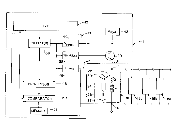
BRIEF DESCRIPTION OF THE DRAWING
Fig 1 is a s~h~-m~tir. diagram of a control circuit according to the present in ention;
Fig. 2A is a waveform showing the application of a voltage during a predetern ined
time period dt; and
Fig. 2B is a waveform showing a transient current value at the end of the
predeterrnined time period.
BEST MODE FOR CARRYING OUT THE INVENTION
Referring now to the drawings, and in particular Fig. 1, it can be seen that a device
for identifying the number of inductive loads in parallel connected thereto is design~t~d
21 85280
generally by the number 10. Generally, the device 10 includes a gun driver 11 with an
input/output device 12, a first terminal 14, a second terminal 16 and a dispensing device
or gun 18. It will be appreciated that any nurnber of dispensing devices, ~sign~t~d as 18
with a letter suffL~c such as 18a and so on, could also be connected between the first and
5 second t~rrnin~lc 14 and 16, respectively. It will also be understood that each dispensing
device 18, 18a, 18b, etc., has an equivalent value of in~llct~n~e. Also in~ln~ed in the gun
driver 11 is a micro-controller 20 which is co~leot~d to the input/output device 12, wherein
the micro-controller 20 dt tr~ f S the number of dispensing devices 18 connected between
the first and second tennin~l~ 14, 16, respectively, and generates an operating current 21
10 which is employed to drive the dispensing devices 18. Although in the preferred
embodiment the micro-controller 20 only ~et~rrnin~s whether there are 0, 1, 2, 3 or 4
dispensing devices connected to the gun driver 11, it will be appreciated that any number
of like dispensing devices could be det~rrnin~d from an ap~lo~liate micro-controller.
In particular, it will be appreciated that for each dispensing device 18 cormected
15 between the first and second tennin~l.c 14 and 16, respectively, there is a corresponding
solenoid 22. The solenoid 22 includes a movable member, such as a plunger 24 which may
be biased by a spring 26 that is interposed between the movable plunger 24 and a fixed
e~lellce 28, such as the gun body. The movable plunger 24 is in an operative relationship
with an orifice 30 such that when the movable-plunger 24 is moved, the dispensing material
20 contained within the dispenser 18 is p~-Tnitted to flow under pressure through the orifice
30 onto the desired object. The movable plunger 24 is actuated by the application of
current through the coil 33 of the solenoid 22 which has an in~lnct~n~e 32 and a resistance
34.
To insure the proper operation of the dispenser 18, it is imperative that the actuation
25 of the movable plunger 24 be precisely controlled. To accomplish this, current is
modulated to the solenoid 18 in various stages. In the first stage, a high level of current,
commonly known as a "pull-in" current, is employed to overcome the force applied by the
spring 26 and the viscosity of the material contained within the dispenser 18 to move the
plunger 24 away from the orifice 30 into a dispensing position. In the second stage, a
30 "holding current," which is appreciably less than the pull-in current, is employed to hold
:
21 85280
-- 6 -
the movable plunger 24 in place. It is desirable to have a holding current that is reduced
- in value, which ~Il;l~illli~s the amount of heat generated in the ~ n~e 34 of the coil 33,
so as to not degrade the inc~ tion of the coil or to cause the coil to fail, while also
reducing the energy nece~s~y to drive it. In the final stage, the holding current is quickly
5 dissipated from the solenoid æ SO as to quickly close the movable plunger 24 upon the
orifice 30. These various stages of current application and removal must be precisely
controlled so as to facilitate the smooth assembly line operation of the dispensing devices
18. To ensure that the proper level of operating current 21 is applied to the plurality of
solenoids æ, it is il~CldLivc: to apply the proper m~gnit~lde of current to the gun modules.
10 Too much current may cause them to fail while too little may cause them not to open or to
open or close late. Therefore, it is important to know the number of solenoids so that the
proper amount of current is employed.
To imp~PTnPnt the proper application of the operating current 21, the micro-controller
20 includes an initiator 36. The initiator 36 receives operator input from the input/output
15 device 12, including but not limited to what pattern is required to be applied to the
p~k~gjng materials and the lelllp~l~Lu~ and viscosity of the fluid to be dispensed. Based
upon the operator input, the initiator 36 generates a voltage impulse 38 which is connected
to and received by the base of a transistor 40. Connected to the collector of the transistor
40 is a nominal voltage supply (Vnom) 42 which provides power to the dispensers 18 when
20 the transistor 40 is toggled to an "on" position. Also co~ec~d to the collector of the
ol 40 is a voltage feedback sensor 44 which is contained within the micro-controller
20. The voltage feedback sensor 44 detP1min.os what the applied voltage (Vapp) is when
the transistor 40 is toggled on by the voltage impulse received from generator 38.
Connected to the emitter of transistor 40 is a current feedback sensor 46 which senses a
25 feedback current 47 flowing along the operating current signal line 21 when the transistOr
40 is on. It will be appreciated that the voltage feedback sensor 44 trans~its a voltage
feedback value to the initiator 36. Likewise, the current feedback sensor 46 transmits a
current fee~lbark value to the initiator 36.
The values collected by the initiator 36 are then sent to a processor 48. The processor
30 48 measures and scales the current feedback value according to a ratio of the nominal
_ 21 85280
voltage supply 42 and the applied voltage sensed by the voltage feedback sensor 44 so as
to generate an actual value for the operating current that is flowing through the first and
second terminals 14 and 16, respectively. A comparator 50 receives the actual operating
current value generated by the plocesso~ 48 and compares this value with a plurality of
predetermined ranges of current values correlating to the possible number of dispensing
devices 18 col~n~ ed between the first and second t~nnin~lc 14 and 16, respectively. Those
skilled in the art will appreciate that when the actual current value falls within one of the
pred~r~ "~i"~d ranges of current, co~ ~a~ol 50 L~ this information via line 51 to the
input/output device 12. Accordingly, the input/output device 12 instructs the micro-
controller 20 as to what values of pull-in current and holding current should be generated
to drive the respective coil of each gun module.
It will be understood that in order to ~et~nnin~ the number of solenoids connPcted
between the first and second t~nnin~li 14 and 16, respectively, it is required that the
theoretical steady state and transient currents of the solenoid or solenoids 22 be defined and
colllp~ed to the actual measured current values det~nninrd by an identi~lcation test. The
theoretical values are ~et~nnin~d by the equations presented below.
In particular, the steady state current is defined by the following equation:
I=Vapp/R (1)
where Vapp is the applied voltage m~gnitll~e in DC volts as monitored by the voltage
feedback sensor 44 and where R is the solenoid resistance 34.
The transient current in a solenoid is defined by the following equation:
dI/dt=Vapp/L (2)
where dI/dt is the measured slope of the current at Vapp in amps/second and where L is
the solenoid in~ct~nre 32.
While the total rPsi~t~nre of the solenoid 22 can vary with changes in temperature,
such as from the heat of the adhesive flowing through the dispenser 18 and any heat
generated by the resict~nre 34 of the coil, it will be appreciated that the value of the
inllllct~nre 32 remains basically constant.
Because the value of the in~lct~nre 32 is a known or a reference value, as dictated
by the solenoid design, the value of dI can be defined as a reference, dIref. It will be
21~528o
appreciated that during the i~lPntific~tinn test, the value of dIref must be kept low so as to
prevent the m~gn~tir force O~neldl~d in the intll-rt~n~e 32 frorn moving the movable plunger
24 from the seat to allow fluid to be dispensed from the orifice 30. It will also be
appreciated that the value of dIref must be kept low enough so that the effect of resistance
5 34 is negligible. A(l~itinn~lly, solenoids 22 require the use of a nominal operating voltage
42. With the above information, dIref can now be defined by the following equation:
dIref=(Vnom*dt)/L (3)
where dIref is the current m~gnihlde. reference for one solenoid 22 and where dt is the
voltage impulse duration to generate dIref at the nominal o~e.dLillg voltage 42 (Vnom). The
10 current lc;f~.ellces for the dirr~ t possible number of solenoids are d~t~,.llil~d by
multiplying that number by the value of dIref. Those skilled in the art will appreciate that
it is llecessdly to set a tolerance window or a predet~rmin~d range of current values around
the iefele.lce feedback current (dIrefl value due to variations in the m~m~f~rhlrin~ of the
solenoids 22. These predet~rminpd ranges are stored in memory 52.
As those skilled in the art will a~ cidL~, the nominal voltage supply 42 (Vnom) may
vary due to normal line voltage variations received from various power supplies. To
compensate for these v~ri~tionC, a correction factor "k" can be applied to the measured
feedback current value 47 in order to scale it back to the nominal voltage supply 42 from
the applied voltage Vapp sensed by the voltage feedback sensor 44. This is exemplified by
20 the following equations:
k=Vnom/Vapp (4)
dIact=k*dI (5)
where dI is the llled~.ued feedback current value 47 and where dIact is the corrected actual
value of the current due to line voltage variations in the nominal voltage supply 42. The
25 actual current value dIact is compared with the range of current values stored in memory
52, and if the actual current value is within one of the ranges, the number of solenoids 22
or inductive loads colll,ected in parallel can be detl-rminPd
Based upon the f~L~Ooing e~ nc and with lC:reLel1ce to Figs 2A and 2B, the micro-
controller 20 gell~ldL~s a voltage impulse through generator 38 that momentarily toggles the
30 LLdl~i~L~r 40 to an "on" position. The voltage impulse signal (Vapp) is provided for a fixed
2l8528o
duration of dt (seconds). At the end of dt, the feedback current 47 (di in Fig. 2B) and the
feedback voltage 44 are sensed and received by the initiator 36. The initiator 36 then
provides these values to the processor 48 which performs the equations indicated above.
The derived actual current value (dIact) is then col~ed to zero and to the applo~Liate
pairs of reference values stored in memory 52. Each pair of reference values, for each
solenoid, provides the worst case positive and negative tolerances for each respective
number of solenoids in parallel. When the comparator 50 finds a match, the number of
inductive loads/solenoids in parallel is found, stored and communicated by the micro-
controller 20 to the input/output device 12. Of course, if no solenoid is connected between
the first and second terminals 14 and 16, les~ec~ively, no current is developed during the
application of the voltage irnpulse 38, and this information is, accordingly, tr~n~mitt~d to
the input/output device 12.
It is a~palellL then from the above description of the operation of the device 10 for
identifying the number of inductive loads cnnn~-ct~d in parallel that the problems associated
with manually setting switches and/or jumpers have been overcome. By reducing possible
sources of error during setup or wiring, the likelihood of too much or too little current
being applied to the solenoid devices is substantially reduced. If a low current were to be
received by a solenoid device, the opening and closure of the movable armature 24 from
the orifice 30 would not be acceptable for a high speed assembly operation. In particular,
it will be appreciated that the patterns of deposited material would be missing or out of
synchn~ dLion with the location of the boxes on the assembly line. In a sirnilar manner,
an overly high application of current to the solenoids 18 is also prevented. This prevents
the solenoids from overh~ting and becoming damaged and also from d~m~ging any other
components within the dispensing gun device.
Yet another advantage of the present invention is that by quickly det~rmining the
number of solenoids col~lc~;~ed in parallel to the dispensing gun device, the proper
tion for the pull-in currents and holding currents can be quic~cly obtained based upon
the inforrnation provided at the input/output device 12. It should also be appleciated that
if an actual current value is derived that does not fit wit_in one of the predetermined ranges
in memory 52, it is likely that one of the solenoids 18 is not fim~tioning properly. As such,
~- 2 1 85280
- 10 -
the micro-controller 20 can send an appropriate error message to the input/output device
12 so that the operator can take corrective action.
Thus, it can be seen tnat the objects of the invention have been satisfied by the
structure l l~se~ d above. It should be apparent to those skilled in the art that the objects
S of the present invention could be practiced with any number of solenoids or adapted to
perform with any size of solenoid.
While the preferred embodiment of the invention has been p~ese,1~ed and described
in detail, it will be understood that the invention is not ~irnited thereto or thereby. As such,
similar configurations may be used in the construction of the invention to meet the various
10 needs of the end user. Accordingly, for an ap~l~ciation of the true scope and breadth of
the invention, reference should be made to the following claims.