Note : Les descriptions sont présentées dans la langue officielle dans laquelle elles ont été soumises.
WO 95/25456 ~ ~ , ~ PCT/US95/03713
MAGNETIC SEALING STRIPS FOR DRAPERIES AND LININGS
BACKGROUND OF THE INVENTION
1. Field of the Inv i n
The present invention is directed to blackout drapery linings, and more
particularly, to retrofit linings which may be installed for use with
preexisting
drapery.
2. Description of the Prior Art
Conventional draperies are primarily designed for style and appearance, and
are generally made from premium fabrics of various colors. While such fabrics
may serve the purF~ose of creating a desired visual effect, and may provide a
desired level of privacy, they are generally ineffective for preventing a
substantial
quantity of light penetration into a room from outside sources, and a
corresponding
illumination of the room to an undesired level.
The problem of undesired illumination is particularly noticeable in any
room used for sleeping. Even with eyelids closed, 20 % of this undesired
environmental light still is admitted to the eyes, interfering with proper
sleep.
Lack of sleep is related to other health problems, and results in lost
productivity
in the work-place due to related mistakes, illnesses and absences. Further,
the
SUBSTITUTE SHEET (RULE 26)
WO 95/25456 , PCT1US95/03713
218619
2
Department of Transportation estimates that 200,000 traffic accidents each
year
may be sleep related.
For those living in densely populated urban or suburban areas, the amount
of light penetration into a bedroom at night may be considerable due to
sources
such as street lights, light from adjacent buildings and automobile
headlights.
However, the problem of unwanted light penetration is especially acute for
those
who sleep during the daytime, for example, the 20 million shift workers who
work
at night. Napping infants are also deprived of sleep due to unwanted
penetration
of sunlight.
Accordingly, elimination of undesired light from bedrooms is a desirable
goal. Blackout drapery are known in the art, and serve to eliminate unwanted
light
penetration. With reference to Fig. 1, such linings 1 are hung adjacent
drapery
3 and include a plurality of loops 21 extending from an upper edge which are
designed to suspend the lining from a plurality of drapery hooks 5. Hooks 5
are
the same drapery hooks from which drapery 3 is suspended. However, in known
linings, the degree to which light penetration may be precluded is limited due
to
light penetrating around the outer edges of the linings, that is, between the
linings
and the window frame. The degree of light blockage is further degraded for
multi-panel draperies, which require the use of a corresponding number of
blackout lining panels. In this situation, unwanted light penetrates through
the slit
between adjacent panels.
SUMMARY OF THE INVENTION
The present invention is directed to a drapery including two panels having
inner vertical edges which may be overlapped. Each inner vertical edge
includes
SUBSTITUTE SHEET (RULE 2fi)
2186219
3
a hem. The hems are formed by folding over the edges and stitching along a
vertical
line so as to leave a channel formed between the hem and an opposing portion
of the
panel. The vertical stitching; line includes a gap at one location so as to
leave an
opening into the channel. A magnetic sealing strip is removably disposable
within the
channels by insertion into t:he channel through the opening. When the panels
are
overlapped, the inner vertical edges may be secured to each other by the
magnetic
sealing strips.
In a further embodiment the panels include upper and lower hems formed by
folding over the upper and lower edges of the panels and stitching along upper
and lower horizontal lines. A portion of the upper stitching lines serves as
an upper
boundary of the channels, and a portion of the lower stitching line serves as
a lower
boundary of the cha~mels. The opening terminates adjacent the upper stitching
line.
In a further embodiment, a second vertical stitching line is disposed between
the inner vertical edge of the panels and the vertical stitching line. The
second vertical
stitching line forms ;gin inner vertical boundary for the channel.
In accordance with ,m aspect of the invention there is provided a window
covering comprising;:
two panels having inner vertical edges which may be overlapped with each
other, each said inner vertical edge including a hem, each said hem formed by
folding
over the edge and stitching along a vertical line so as to form a sealing
strip channel
between the hem and an opposing portion of the panel, the sealing strip
channel of
each said panel inc:hiding at: least one sealing strip opening formed in at
least one
location so as to leave at least one opening into said channel; and
a removable magnetic; sealing strip removably disposed within each of said
P
2186219
3a
channels, said magnetic sealing strip capable of being repeatedly inserted and
removed through said at least one opening;
wherein, when said panels are overlapped, said inner vertical edges are
secured to each other by said removable magnetic sealing strips.
In accordance with another aspect of the invention there is provided the
combination of a drapery and a lining, said drapery comprising a pair of
drapery
panels, said lining comprising a corresponding pair of lining panels
disposable
adjacent said drapery panels, each said lining panel having inner vertical
edges which
may be overlapped with each other, each said inner vertical edge including a
hem,
each said hem formed by folding over the edge and stitching along a vertical
line so as
to leave a sealing strip charnnel formed between the hem and an opposing
portion of
the panel and furthc,r including at least one opening into said sealing strip
channel,
said combination further comprising magnetic sealing strips removably
disposable
within each of said channels by insertion into and removal from each said
channel
through said sealing; strip opening, wherein, when said lining panels are
overlapped,
said inner vertical edges are secured to each other by said magnetic sealing
strips.
In accordance with a further aspect of the invention there is provided a
method for forming a window covering panel comprising:
folding over a vertical edge of the panel to form a vertical hem;
stitching said vertical hem along a vertical line;
folding over a lower horizontal edge of the panel to form a horizontal hem;
stitching said horizontal hem along a horizontal line such that a sealing
strip
channel is defined within sand vertical hem with the horizontal and vertical
stitching
lines forming boundaries for said channel;
A
2186219
3b
forming an opening; to said sealing strip channel; and
removably disposing a magnetic sealing strip in said channel by repeatedly
inserting and removing the. magnetic sealing strip through said opening to the
sealing
strip channel.
BRIEF DESCRIPTION OF THE DRAWINGS
Fig. 1 is a rear view of a prior art drapery lining.
Fig. 2a is ~~ rear view of a drapery lining according to one embodiment of the
invention disposedl adjacent a drapery.
Fig. 2b is a rear view of a drapery lining according to a second embodiment of
the invention disposed adjacent a drapery.
Fig. 2c is .a rear view of one panel of a drapery lining according to a
further
embodiment of the. invention.
A
WO 95/25456 PGTIUS95/03713
21~~~21'~ 4 _
Fig. 3 is a partial cutaway view showing the drapery and lining disposed
on a transverse rod.
Fig. 4 is a front view of a window frame showing a plurality of hook and
loop strips forming part of one embodiment of the invention.
Fig. 5 is an overhead view of a gripper element in accordance with a
further embodiment: of the invention.
Fig. 6a is am overhead view showing the gripper clip attached to and
closing a blackout lining and drapery.
Fig. 6b is aui overhead view showing the gripper clip attached to the left
drapery lining.
Fig. 7 is a F~erspective view showing a plurality of gripper clips attached
to one lining.
Fig. 8 is a partial c;utaway view showing the gripper clip of Figure 5
disposed so as to close the drapery and lining.
Fig. 9 is a rear view of a drapery lining having preformed magnetic sealing
strips disposed on tlhe inner vertical edges according to a further embodiment
of
the invention.
Figs. l0a and lOb .are front views disclosing the preformed magnetic
sealing strips before: and after construction.
Fig. 11 is au~ overhead view of a sealing strip according to a further
embodiment of the invention.
Fig. 12 is a perspective view showing the positioning of fastening strips on
the upper surfaces of the transverse rod frame.
SUI3SSTI11JTE SHEET (RULE 26)
WO 95/25456 ~ ~ ~ ~ 19 PCT/U895/03713
Fig. 13 is a, perspective view showing the sealing strip of Figure 11
disposed on the upper surface of the rod frame.
DETAILED DESC:ItIPTION OF THE PREFERRED EMBODIIVVIEENTS
With referen~;x to Fig. 2a, a retrofit blackout drapery lining attached to a
drapery according to the present invention is shown. Retro-fit blackout lining
10
includes two panels l0a and l Ob which are substantially 100 % light
impermeable,
and which include a. plurality of integrally formed loops 21 disposed across
and
extending from the upper edge. Each panel of lining 10 further includes cord
access slot 7 formed theretlzrough near the upper and outer vertical edge. A
plurality of magnets 11 are :sewn inside a hem formed on the inner vertical
edge
of each panel l0a .and lOb. Hook and loop fastening strips 9, for example,
VELCRO, are disposed along the outer vertical edges of each panel of lining
10,
and extend from top to bottom. Strips 9 are disposed on the inner side of
panels
l0a and lOb, that is,, the side; which in use would face the window frame. In
the
situation shown where the lining includes two panels, the outer vertical edge
of
panel l0a and the outer vertical edge of panel lOb serve as the outer vertical
edges
of the lining as a whole. Of course, if the lining includes only one panel,
then the
outer vertical edges of that one panel would serve as the outer vertical edges
of the
lining as a whole, a~ld each ~xige would have strip 9 disposed thereon.
With further reference to Fig. 2a and to Fig. 3, drapery 30 also includes
two panels 30a and 30b, each having a plurality of conventional drapery pins
or
hooks 5 with which the draperies may be suspended from conventional overhead
drapery rods. Retrofit lining; 10 may be installed into a preexisting drapery
30 by
first removing the drapery panels from the drapery rods, and laying the
drapery
SlIBSIITUTE SHEET (nliLE 26~
WO 95/25456 PCT/US95/03713
213 E~ 2 ~ '~
6
panels face down. Each panel of lining 10 is laid adjacent the interior side
of a
corresponding drapery panel, with loops 21 disposed adjacent hooks or pins 5.
Loops 21 are disposed over pins 5 to secure each panel of lining 10 adjacent
each
panel of drapery 30. The combined drapery and lining is then rehung on
transverse drapery rods 15 as shown in Fig. 3.
In this manner, a conventional and preexisting drapery may be converted
into a blackout drapery which eliminates unwanted light penetration. The
purchase
of new drapery or the installation of new drapery rods is avoided. Since
lining 10
is suspended from the same pins as drapery 30, lining 10 is opened and closed
simultaneously with drapery 30. Thus, the blackout effect is automatically
achieved every time the draperies are closed, with the lining fully extended
across
the window to allow a complete blackout effect. In addition, the lining acts
as a
thermal barrier to provide better room insulation, prevents fading of the
drapery
from exposure to sunlight, and other damage which results from the effects of
ultraviolet rays.
With further reference to Fig. 3, the combined drapery 30 and lining 10 is
shown suspended from transverse rod 15. The inner vertical edges of the left
and
right lining panels are overlapped, and securely fixed to each other by
magnets 11,
eliminating formation of cracks between each lining panel which otherwise
would
allow sunlight to penetrate into the room. The present invention thus
increases the
degree of the blackout effect achieved by the blackout drapery lining for
multi-
panel draperies. Alternatively, as shown in Fig. 2b, hook and loop fastening
strips
12, for example, VELCRO, could be used in place of magnets 11 to removably
secure the inner vertical edges of each panel.
SL1BSTlTUTE SHEET (RULE 26)
WO 95/25456 21 ~i 6 219 pCT/US95/03713
7
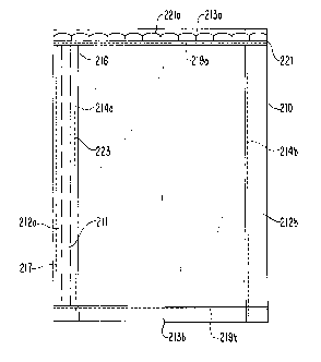
With refere:nce to Figure 2c, an alternative construction of a blackout lining
panel according to the preaent invention is shown. Although only one panel is
shown in Figure ~:c, as with the embodiments of figures 2a and 2b, lining
panel
210 would form part of a two-piece lining, with each panel disposed adjacent a
corresponding drapery pmel. Lining panel 210 is folded over at the sides to
include inner and outer vertical hems 212a and 212b, respectively, and top and
bottom horizontal hems 213a and 213b, respectively. The terms inner and outer
refer to the ultimate placement of the finished panel relative to the window
frame.
Preferably, hems 2;12a and 212b have a width of 1.25-1.5", and are formed
before
hems 213a and 21:3b by first folding over the inner and outer vertical edges
of the
panel, and stitching along lines 214a and 214b, respectively. As shown, outer
stitch line 214b extends aliong the entire length of panel 210. However, inner
stitch line 214a ~terminatEa below the top edge of the panel, for example,
approximately 4" below the top. Secondary vertical stitch line 217 also is
provided near the inner vertical edge of lining panel 210, for example,
approximately .25" from the edge. Secondary stitch line 217 extends entirely
from
the top edge to the: bottom edge of the panel.
Panel 210 i.s folde:d over at top and bottom edges to form hems 213a and
213b. Hems 213 nnay be approximately 1.25-1.5" in width, and are stitched
along
upper horizontal stitch line 219a and lower horizontal stitch line 219b, which
extend substantially from the inner to the outer vertical edge of the panel.
Braided
strip 221 having freely extE:nding loops 221a is disposed along and secured to
the
lower edge of upper hem 213a. Preferably, strip 221 is secured to upper hem
213a by upper stitch line 219a.
;iU8STITUTE SHEET (RULE 28)
WO 95125456 ~ PCT/US95I03713
8
After formation of upper hem 213a, a gap of approximately 1 " remains
between the upper end of inner vertical stitch line 214a and the lower edge of
upper hem 213a. This gap results in the formation of opening 216 formed in
inner
vertical hem 212a. Opening 216 allows access to channel 223 formed within
inner
hem 212a, between vertical stitch lines 214a and 217 and horizontal stitch
lines
219a and 219b. Flexible magnetic sealing strip 211 is disposable in channel
223,
by insertion through opening 216. Flexible strip 211 may be bent as necessary
to
allow it to be disposed through opening 216, and slid downwardly in channel
223
until the bottom edge of strip 211 is adjacent lower stitch line 219. The
length of
strip 211 is approximately the same as the length of channel 223 such that
strip
211 extends throughout substantially the entire channel. Since strip 211 is
confined in channel 223 only by stitch lines 214a, 217, 219a and 219b which
form
channel 223, and is not further secured in the channel. Strip 211 may be
removed
from channel 223 through opening 216 in the reverse manner from which it was
inserted. Strips 211 may be made of thermal plastic impregnated with barium
ferrite. For example, suitable magnetic strips are sold by Magnet Sales
Manufacturing Company of Culver City, California under the name ULTRA-
MAG.
Panel 210 would be suspended adjacent one drapery panel of a two-part
drapery panel in a similar manner as shown in Figures 2a and 2b, with magnetic
strip 211 disposed along the inner vertical edge relative to the window frame.
A
second panel 210 would be suspended adjacent the second drapery panel, with
magnetic strip 211 disposed along the inner vertical edge. The second panel
would
be formed with magnetic strip 211 disposed along the opposite vertical edge of
the
SUBSTITUTE SHEET (RULE 26)
WO 95/25456 ~, 2 ~ ~ PGT/L1S95/03713
panel, that is, in the same rear view of the panel as shown in Figure 2c,
channel
223 and magnetic strip 211 would be disposed along the right side of the
figure.
In order to achieve a blackout effect, the inner vertical edges of the left
and right
panels would be overlapped" and the magnetic sealing strips would be brought
into
contact in the same manner as shown in Figure 3, thereby sealing the inner
edges
of the lining panels.
The embodiment shown in Figure 2c provides a blackout effect for the
center of a two-panel lining;, preventing light penetration through the center
of the
lining where the two panels meet. Further, as discussed, this embodiment
provides the further advantage that magnetic strip 211 is removably disposable
within channel 223,. that is, strip 211 may be removed by simply sliding it
out of
opening 216 in the reverse manner from which it was inserted. Thus, strip 211
may be removed easily to allow for cleaning of the lining panels. Although
this
embodiment is described with reference to lining panels, it can apply to any
type
of window covering. For example, the invention could be applied to the drapery
itself, that is, channel 223 could be formed directly in drapery panels. The
term
drapery also includes lighter weight curtains. Further, the lining panel could
be
of the retrofit type as disclosed in Figures 2a and 2c, which are sold
separately
from the drapery, ;and then are suspended adjacent the drapery panels from the
same rods. Alteniatively, the lining panels could be of the type which are
suspended adjacent the drapery from a separate rod. The lining panels also may
be of the type which are attached to the drapery panels, for example, the
lining
panels may be sewed adjacent to the drapery panels, and sold together
therewith.
SUBSTITUTE SHEET (RULE 26)
WO 95125456 ~ ~ ~ ~ '~ ~ y PCT/US95/03713
,
As a further alternative, a plurality of gripper clips 20 could be used to
removably secure the inner vertical edges of each panel, as shown in Fig. 8.
Preferably two or three gripper clips 20 which are vertically spaced as shown
would be used to securely close the inner vertical edges of lining 1. Gripper
clips
may be molded in flexible plastic/nylon, and may be spaced at approximately
18" along the lining. As shown in Figure 5, gripper clips 20 have a double
"bobby pin" shape, with serrated inner surfaces 24 to grip the lining and
drapery
fabric. Ends 22 of clips 20 are bent outwardly so as to preclude snagging of
the
lining or drapery.
With further reference to Figs. 6a and 6b, the manner in which clips 20
secure the inner edges of lining 10 and drapery 30 is disclosed. With the
drapery
and lining closed, the "inner loop" of clip 20 is flexed and secured over both
left
drapery panel 30a and left lining panel 10a, which for purposes of example are
disposed inward of right drapery panel 30b and right lining panel lOb. The
flexibility of clip 20 holds the drapery and lining panels taut. Right lining
panel
lOb is disposed in the "outer loop" of clip 20, thereby securing the inner
vertical
edges of lining panels l0a and lOb to each other in an overlapping
configuration,
and precluding light penetration therebetween. Right drapery panel 30b is
allowed
to fall in front of clips 20, hiding them from view. Although as shown in Fig.
6a
the left panels are disposed inwardly of the right panels, the panels could
also be
secured together by reversing the clip and disposing the right panels inwardly
of
the left panels.
With further reference to Fig. 6b, the flexibility and no-snag design of clips
20 ensures that if the drapery is opened while the clips are in use, the clips
will
SUBSTITUTE SHEET (RULE 26)
WO 95/25456 ~ ~ ~ ~ ~ PCT/US95/03713
11
remain on one side: withoul: damaging the drapery or lining. For example,
clips
20 remain attachea~ to the left side. Further, left drapery panel 30a can be
removed from inside the imaer loop of clips 20, and allowed to fall in front
of the
clips. Thus, as shown in F:ig. 6b, clips 20 will remain attached to only left
lining
panel 10a, and will be hidden from view by left drapery panel 30a. As shown in
Fig. 7, clips 20 ma;y be sewed to left lining panel 10a, permanently securing
them
thereon. Holes 26 are provided for this purpose.
With reference to lFig. 4, the manner in which the present invention
increases the blackout effeca for both single and multi-panel draperies is
shown.
Vertically extending hooks and loop fastening strips 19, for example, VELCRO~
strips, are fixed toy the wall adjacent each side of window 17. Strips 19 are
conventional and may include adhesive back surfaces for applying to the wall.
Strips 19 are fixed to the wall so as to line up with the ends of rod brackets
15,
so as to be essentially adjacent strips 9 on lining 10. After the combined
lining
and drapery is rehung on hooks 5, drapery cord 13 is pulled through cord
access
slot 7 and allowedl to hang exteriorly of lining 10. Thereafter, strips 9 are
removably fixed to strips 19, thereby securing both vertical sides of lining
10 to
the wall or windov~r frame, eliminating any cracks therebetwe~n through which
light could penetrate. A substantially complete light-proof seal is thus
achieved
at the outer edge of the lining, with complete access to the drapery cord
maintained so that the drapery can be easily opened and closed.
Although as shown in Fig. 2a, lining 10 is in the form of two separate
panels which are designed for use with a two-panel drapery, lining 10 could
also
comprise a single panel for use with a single panel drapery. Such a lining
would
~)BSTITUTE SHEET (RULE 26)
WO 95125456
8 6 Z 19 pCT~S95/03713
1~
be attached to the drapery in the same way as shown in Fig. 2a, and would have
strip 9 disposed on each outer vertical edge.
With reference to Figure 9, a further embodiment of the invention is
disclosed in which individual magnets 11 or hook and loop fastening strips 12
are
replaced by magnetic sealing strips 120. Magnetic sealing strips 120 are
prepared
separately from lining panels l0a and lOb, and include a plurality of spaced
magnets 11 which are secured between the overlapped upper and lower surfaces
of a rectangular fabric strip. Prepared sealing strips 120 are secured to the
inner
vertical edges of the panels, and may be overlapped, with magnets 11 coming
into
contact with each other so as to allow the inner vertical edges of panels l0a
and
lOb to be secured together and prevent penetration of light therethrough.
With reference to Figures l0a and lOb, the construction of sealing strips
120 is shown. Strips 120 are made from rectangular sheet 121 of a relatively
thin
fabric. One vertical half surface of sheet 121 is coated with an adhesive
layer
124, with a border maintained along the outer edge. Magnets 11 are disposed at
various vertical locations on the same vertical half surface of sheet 121 as
adhesive
layer 124. In the shown preferred embodiment, magnets 11 are disposed on
opposite side of rectangular strips 122 of wadding material. Magnets 11 and
strips
122 are secured in position by adhesive layer 124 upon which they are
disposed.
Each group of a pair of magnets 11 and strip 122 of wadding is spaced from the
next group. Magnets 11 and wadding strips 122 are disposed with their longer
edges substantially aligned with the approximate longitudinal axis of sheets
121.
The exact positions of magnets 11 and wadding strips 122 may be marked on
sheet
121 prior to the application of adhesive layer 124 to sheet 121.
SUBSTITUTE SHEET (RULE 26)
WO 95125456 ~ ~ ~ 6 219 PCT/LIS95/03713
13
After magnets 11 and strips 122 are disposed on sheet 121, the sheet is
folded along the approximate longitudinal axis thereof so as to bring the
uncoated
side of sheet 121 adjacent the coated side. The coated and uncoated side are
brought into contaca and thereby secured together by the adhesive, to form a
finished strip as shown in Figure lOb. Finished sealing strip 120 is secured
to the
inner vertical edge of lining panels l0a and lOb in any suitable manner, for
example, by stitching. By forming strips 120 separately from panels l0a and
lOb,
the advantages of a :light-proof inner seal may be realized for a two panel
blackout
lining in which no provision has been made for securing the overlapping inner
vertical edges.
In the prior art, the. curtains and liners are suspended from transverse
drapery rods 15 which generally include three-side frame 40 disposed outwardly
thereof. Frame 40 :is shown in Figure 12. Frame 40 includes longer portion 40a
disposed parallel to rod 15, and shorter portion 40b disposed perpendicularly
to
the wall. Although only one shorter portion 40b is shown, a second shorter
portion 40b would b~e dispos~rd at the opposite end of rod 15. Frame 40
surrounds
an open area through which light may enter the room.
With reference to Figure 11-13, a further embodiment of the invention is
shown which allows; for the preclusion of light entering into the room through
the
open area. Hook o:r loop strips 50 having an adhesive on the surface opposite
of
the hooks or loops, are secured on the upper surfaces of frame 40. Rectangular
overhead sealing strip 52 iincludes sheet 53 made out of a suitable blackout
material, for example, the blackout-type material sold under the name ROCLON'"
by Rockland Industries, which comprises a woven poly-cotton fabric coated with
~SUBS'fITUTE SHEET (RULE 26)
WO 95/25456 2 PCTIUS95/03713
14
three layers of an acrylic based compound, one of which includes an opaque
pigment. Corresponding hook or loops strips 54 are disposed on one of the
longer
edges and both shorter edges of sheet 53. Strips 54 may be secured on sheet 53
by a suitable adhesive. Sealing strip 52 is disposed upon frame 40 so as to
cover
the open area, and block light penetration therethrough, and is secured to
frame
40 by strips 54 which are disposed on corresponding strips 50.
Blackout drapery linings according to the present invention may be made
from conventional fabric materials such as woven textile, knit or non-woven
materials, which are generally coated in a known fashion with an opaque layer
to
achieve a blackout effect. The opaque layer may comprise an acrylic latex
based
compound including an opaque material such as a pigment. Of course, any
suitable blackout material may be used.
This invention has been described in detail in connection with the preferred
embodiments. These embodiments, however, are merely for example only and the
invention is not restricted thereto. It will be understood by those skilled in
the art
that other variations and modifications easily can be made within the scope of
this
invention as defined by the appended claims.
$118STfTUTE SHEET (RULE ?_6)