Sélection de la langue

Search

Sommaire du brevet 2187218 

Énoncé de désistement de responsabilité concernant l'information provenant de tiers

Une partie des informations de ce site Web a été fournie par des sources externes. Le gouvernement du Canada n'assume aucune responsabilité concernant la précision, l'actualité ou la fiabilité des informations fournies par les sources externes. Les utilisateurs qui désirent employer cette information devraient consulter directement la source des informations. Le contenu fourni par les sources externes n'est pas assujetti aux exigences sur les langues officielles, la protection des renseignements personnels et l'accessibilité.

Disponibilité de l'Abrégé et des Revendications

L'apparition de différences dans le texte et l'image des Revendications et de l'Abrégé dépend du moment auquel le document est publié. Les textes des Revendications et de l'Abrégé sont affichés :

  • lorsque la demande peut être examinée par le public;
  • lorsque le brevet est émis (délivrance).
(12) Demande de brevet: (11) CA 2187218
(54) Titre français: SYSTEME DE CIRCUIT POUR L'ALLUMAGE D'UNE LAMPE A DECHARGE HAUTE INTENSITE
(54) Titre anglais: CIRCUIT ARRANGEMENT FOR IGNITION OF A HIGH INTENSITY DISCHARGE LAMP
Statut: Réputée abandonnée et au-delà du délai pour le rétablissement - en attente de la réponse à l’avis de communication rejetée
Données bibliographiques
(51) Classification internationale des brevets (CIB):
  • H05B 41/04 (2006.01)
(72) Inventeurs :
  • BROWN, ALLAN E. (Etats-Unis d'Amérique)
(73) Titulaires :
  • KONINKLIJKE PHILIPS ELECTRONICS N.V.
(71) Demandeurs :
  • KONINKLIJKE PHILIPS ELECTRONICS N.V.
(74) Agent: SMART & BIGGAR LP
(74) Co-agent:
(45) Délivré:
(86) Date de dépôt PCT: 1996-01-23
(87) Mise à la disponibilité du public: 1996-08-15
Licence disponible: S.O.
Cédé au domaine public: S.O.
(25) Langue des documents déposés: Anglais

Traité de coopération en matière de brevets (PCT): Oui
(86) Numéro de la demande PCT: PCT/IB1996/000051
(87) Numéro de publication internationale PCT: WO 1996025022
(85) Entrée nationale: 1996-10-04

(30) Données de priorité de la demande:
Numéro de la demande Pays / territoire Date
08/386,904 (Etats-Unis d'Amérique) 1995-02-07

Abrégés

Abrégé français

L'invention concerne un système de circuit pour allumer une lampe à décharge haute intensité sous la forme d'impulsions d'allumage fournies à la lampe avant et sensiblement pendant toute la durée d'incandescence de la lampe. L'allumeur présent dans le circuit comprend un dispositif bilatéral de commutation du type SIDAC ayant une tension d'amorçage correspondant à la tension de la lampe lorsque la lampe est en mode d'incandescence. Le système de circuit évite sensiblement que la lampe reste dans son mode incandescent pendant une durée de temps prolongée, ce qui minimise la possibilité d'une destruction de la lampe consécutive à une détérioration des électrodes de la lampe.


Abrégé anglais


The invention concerns a circuit arrangement for starting a high intensity discharge lamp requiring energy in the form of ignition
pulses being provided to the lamp prior to and substantially throughout the glow load of the lamp. An ignitor comprised by the circuit
arrangement includes a bilateral switching device such as, but not limited to, a SIDAC having a breakover voltage corresponding to the
lamp voltage during the lamp glow mode. The circuit arrangement substantially eliminates the lamp remaining in its glow mode for a
prolonged period of time thereby minimizing the possibility of lamp destruction from damage to the lamp electrodes.

Revendications

Note : Les revendications sont présentées dans la langue officielle dans laquelle elles ont été soumises.


6
CLAIMS:
1. A circuit arrangement for ignition of a high intensity discharge lamp
having during ignition a glow mode, comprising:
output terminals, and
an ignitor for production at igniting the lamp of ignition pulses prior to and
substantially throughout the glow mode, said ignitor having a voltage sensor for sensing the
voltage across the output terminals and being responsive to the voltage sensor in the
production of ignition pulses.
2. The circuit arrangement of Claim 1, wherein the ignitor includes a
bilateral switching device having a breakover voltage chosen to correspond to the voltage
across the lamp at about the end of the lamp glow mode.
3. The circuit of Claim 2, wherein the ignitor includes a
capacitor coupled to the bilateral switching device and through which the capacitor discharges
at breakover of the bilateral switching device.
4. The circuit arrangement of Claim 3, wherein the bilateral switching device
is a SIDAC.

Description

Note : Les descriptions sont présentées dans la langue officielle dans laquelle elles ont été soumises.

wos6/2so22 P~l,.. , ~.c
1 21872~8
Circuit ~ _ for ignition of a high intensity discharge hmp.
This invention rehtes to a circuit _ for ignition of a high
intensity discharge hmp. In general the circuit _ is fo~med by a balhst for the
HID hmp. It is also possible that the circuit 5 _ is forrned by a separate ignitor.
An HID hmp generally refers to a family of hmps including high
S pressure mercury, high pressure sodium, metsal halide and low pressure sodium. A ~D hmp
has during ignition a glow mode, in which a glow discharge is devdoped in the hmp before
a full arc discharge talces phce. A w..~ ' baUast for powering an HID lamp includes
an ignitor. The ignitor provides nigh voltslge ignition pulses applied to the hmp for starting
the htter.
The energy from the high voltslge pulses generated by the ignitor are
provided to the hmp prior to the hmp entering its glow mode. At the time that the h~np
begins to enter its glow mode, the ignitor is shut off. No high voltslge pulses are generated
during the glow mode. When ignition is successful, the hmp proceeds rapidly through the
glow mode to a stesldy stslte condition, that is, from a glow discharge to an arc dischlrge
15 condition between the hmp's electrodes.
The amount of energy required for successful ignition varies and depends
on factors such as, but not limited to, parti31 pressures of the gasses within the hmp. When
an '~ amount of energy is delivered to the ~ID hmp to ignite the latter, the lamp
can become stuck in its glow mode and never reach a steady stslte (fuU arc) condition.
Repeated e~posure to prolonged periods within the glow mode can
damage the HID hmp electrodes. DeC~ ` of the lamp can result.
, it is desirable to provide an improved HID ignitor having
more reliable ~ID ignition properties. The ignitor, irl particuhr, should avoid prolonged
periods of time withi~the glow mode.
Generally speaking, in ~cc ' with a first aspect of the invention, a
circuit: ~ for ignition of a high intensity discharge lamp, having during ignition a
glow mode, includes output terminals and an ignitor for production at igniting the lamp of

WO 96/25022 1 ~
21 8721 8 2
ignition pulses prior to and at least '1~ throughout the glow mode of the high
intensity discharge ]amp. The ignitor includes a voltage sensor for sensing the voltage across
the output terminals and is responsive to the voltage sensor in its production of ignition
pulses.
S The circuit ~ _ avoids remaining ~e lamp within tho glow mode
for an e~tended period of ~ime by production of ignition pulses not only prior to but also
the glow mode of the high intensitv discharge l~unp. The ignition
pulses produced prior to and ~ throughout the glow mode provide sufficient
energy for successful takeover, that is, for the hmp to move from a glow discharge to arc
10 discharge operating condition. Damage of the lamp electrodes and , lamp
destruction based on prolonged duration of operalion within the glow mode during start-up is
e~
Preferaoly, the ignitor includes a bilateral switching detlice such as, but not
limited to, a SIDAC having a breakover voltage chosen to r to the voltage across15 the lamp at about the end of the lamp's glow mode. The iglutor preferable also includes a
capacitor coupled to the bilateral switching device through which the capacitor discharges at
brealcover of the bilateral switching devioe.
Still other objects and advantages of the invention, will, in part, be
obvious, and will, in part, be apparent from the ~l- .r;. ~t;,..~
The invention " ~ comprises several steps in the relation of one or
more such steps with respect to each of the others, and the device ~ features of~ .. Lu.., ~ ' of elements and: , of parts which are adapted to effect
such steps, all is ~ ' ~ ' in the following detailed disclosure, and the s~ope of the
invention will be indicated in the claims.
For a fuller ~ of the invention, reference is had to the
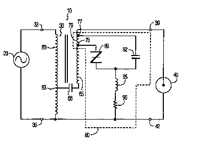
following ~l~crrir~jo~ taken in connection with the ~ , ~ _ drawing which is a circuit
in a~ with the invention.
As shown in the drawing the circuit comprises a ballast 10
which is connected through a p~ur of input terminals 33 and 36 to an A.C. source 20. Ballast
10 provides power through a pair of output terminals 39 and 42 to an HID lamp 40.
_ _ ~

w0 96/25022 2 1 8 7 2 1 8 3 P~
BaDast 10 includw an - . r 60 having a primary winding 60
with a t~p 63. ~Inding 60 is connected to input terminals 33 and 36. A capacitor 66 is
connected between tap 63 and one end of a baDast winding 65. BaDast winding 65 which is
coupled to primary winding 60 includes a first tap 76 and a second t~p 77. 'Bhe
5 portion of baDast winding 65 between taps 76 and 77 is commonly referred to as an ignitor
v~nding 79. '~he other end of baDast winding 65 is ctmnected to output terminal 39.
BaDast winding 65 servw to 1~ ' the Icvd of current flowing
through lamp 40 when the latter is lit. A SIDAC 89 and a qtor 92 are connected
lw~L.~ to t~ps 76 and 77. SIDAC 89 and capacitor 92 are also connected through the
10 serial ~ ' of an inductor 95 and a resistor 96 to the junction joining primary winding
60, input tenninal 36 and output terminal 42 together. Ignitor winding 79, SIDAC 89,
capacitor 92, inductor 95 and resistor 96 serve together as an ignitor (i.e., st~rting circuit~
80. Ignitor 80 C_ll be integrally connected to baDast winding 79. ~ , SIDAC 89
and capacitor 92 can be detachably connected to t~p points 76 and 77, w~
BaDast 10 operatw as follows. Power is supplied from A.C. source 20 to
input terminals 33 and 36 of baDast 10. '~he volt~ge produced by A.C. source 20 is
''' ' to ignite/st~rt lamp 40, the latter of which requirw ignition (st_rting) pulses. The
ignition pulses are provided by ignitor 80. More ~ " as current flows through
capacitor 92, inductor 95 and resistor 96, capacitor 92 ch_rgw to the breakover volt~ge of
20 SIDAC 89.
'~he brea~ver volt~ge is chosen so as to w --r ~ to the ~
glow discharge voltAAge of lamp 40, that is to say equal to or just below the glow discharge
volt~ge of the lamp 40, but well above the voltage of the steady arc of the lamp. '~he glow
discharge voltAge will differ for different typw of HID lunps and depend amongst others on
25 whether the lamp ha~s electrodes with or without emitter. For lamps having electrodes with
emitter the glow discharge voltage wiD be ' '~, lower than in case of , '
lamps having electrodw without emitter. For a person skilled in the art the glow discharge
voltage of a lamp can easily be ' ' ., "~,. In other words, the breakover
voltage is chosen as to w. , ' to the voltAAge across ~he lamp at about the end of the lamp
30 glow mode.
Once the breakover voltage is reached, SIDAC 89 switches from its
previous OFF-state to its ON-stA~te. Capacitor 92 now discharges through ignitor winding 79
and SIDAC 89 rwulting in a voltage pulse produced across ignitor winding 79. Through
action (i.e. baDast 65 acting as an: ' ), a high voltage pulse is
. .

wo96125022 2 l 872 1 8
devdoped across output terTninals 39, 42. The cyclical charging and .'i ' ~- ~ of capacitor
92 produces a series of high voltage pulses across output teTminals 39, 42. By associa~ng d~e
brealcover voltage of SIDAC 89 with the glow mode of lamp 40, ignition pulses are provided
by ignitor 80 prior to and - 1~, throughout the glow mode of lamp 40. DuTing
S tTansition from glow discharge to fuU arc discharge, the voltage across lamp 40 i 'y
increases. FoUowing tlansition into a fuU arc condition (~ ~r), the voltage across lamp
40 L '~ / drops to turn OPF SIDAC 89. ~ " after tTansition to fuU arc
discharge, ignitor 80 is shut O~F.
SIDAC 89 serves as a voltagc sensor for sensing the voltage across output
10 terminals 39 and 42 of ballast 10. Ignitor 80, in response to SIDAC 89 cyclicaUy tuTning ON
and OFF, provides a sufTicient amount of energy for successful talceover of lamp 40. In
paTticular, the continuous pToduction of ignition pulses prior to and at least ! ' '- '1~,
' __' the glow mode avoids l~unp 40 ~eTnaining within the glow mode for an e~tended
period of time. Damage of the lamp dectrodes and; , lamp dest~uction based on
15 prolonged duTation within the glow mode is ' "~
For exampb, when lamp 40 is of a metal halide type, nominally Tated at
150 watts, 95 volts with SIDAC 89 having a brea~over voltage of between about 110-12S
volts, a voltage pulse of about llG125 volts is applied across ignitor winding 79. A voltage
of about 1800 to 3S00 volts is developed across output terminals 39, 42 for star~ng the lamp.
The SIDAC breakover of about 110-12S volts ~ to a lamp voltage of between 150v
- 200v, .~L~. The cycle of charging capacitor 92 until reaching the SIDAC brea~over
voltage resulting in the generation of a high voltage pulse applied to lamp 40 is repeated
prior to and at least ' 'ly throughout the glow mode of lamp 40. Ignitor 80 is shut
OFP at the end of the glow Tnode.
2S More ~ " once lamp 40 is lit, the voltage across SIDAC 89 drops
below its breakover voltage. Ignitor 80 is no longer able to produce a voltage pulse across
ignitor winding 79. In other words, as long as l~unp 40 remains lit, ignitor 80 will produce
no additional volhge pulses.
In ~ with the preferred ' ' of the invention, baUast 30
30 is a 150 watt metal halide conshnt wattage ' (CWA) available from Advance
T-- ' Company of Rosemont, IUinois as paTt no. 71A5486. Capacitor 66 is nominally
Tated at 22.5 I~F, 240 volts. SIDAC 89 is available from ~ ElectTic Mfg. Co., Ltd.
as Part No. KlV12 and has a nominally Tated brealcover voltage of about 110-125 volts.
Capacitor 92 is nominally rated at about 0.33 ' ' Lamp 40 is a high intensity

WO 96/25022 1--
2187218 5
discharge type, such as but not limited to, a 150 watt, 95 volt metal halide type. Inductor 96
typically indudes two serial connected coils, each nominally rated at 22 ' '
Resistor 95 is nominally rated at 3.5 ~ohm.
As now can be readily 5" ': 1, the invention provides an improved
S ignition in which ignition pulses are produced p~ior to and at least 'y throughout
the glow mode of lamp 40. Prolonged periods of time of lamp operation within the glow
modc are ~ , eliminated by providing sufficient energy for successful talceover of
the lamp 40.
It will thus be seen that the objects set forth above and those made
10 appalent from the preceding d~rtinn. are efficiently obtained and since certain dlanges
may be made in the above without departing from the spi~it and scope of the
invention, it is intended that aU n;atter contained in the above ~' and shown in the
drawings shall be inte~preted as illust~ative and not in a limiting sense.

Dessin représentatif
Une figure unique qui représente un dessin illustrant l'invention.
États administratifs

2024-08-01 : Dans le cadre de la transition vers les Brevets de nouvelle génération (BNG), la base de données sur les brevets canadiens (BDBC) contient désormais un Historique d'événement plus détaillé, qui reproduit le Journal des événements de notre nouvelle solution interne.

Veuillez noter que les événements débutant par « Inactive : » se réfèrent à des événements qui ne sont plus utilisés dans notre nouvelle solution interne.

Pour une meilleure compréhension de l'état de la demande ou brevet qui figure sur cette page, la rubrique Mise en garde , et les descriptions de Brevet , Historique d'événement , Taxes périodiques et Historique des paiements devraient être consultées.

Historique d'événement

Description Date
Le délai pour l'annulation est expiré 2004-01-23
Demande non rétablie avant l'échéance 2004-01-23
Réputée abandonnée - omission de répondre à un avis sur les taxes pour le maintien en état 2003-01-23
Inactive : Abandon.-RE+surtaxe impayées-Corr envoyée 2003-01-23
Demande publiée (accessible au public) 1996-08-15

Historique d'abandonnement

Date d'abandonnement Raison Date de rétablissement
2003-01-23

Taxes périodiques

Le dernier paiement a été reçu le 2001-12-13

Avis : Si le paiement en totalité n'a pas été reçu au plus tard à la date indiquée, une taxe supplémentaire peut être imposée, soit une des taxes suivantes :

  • taxe de rétablissement ;
  • taxe pour paiement en souffrance ; ou
  • taxe additionnelle pour le renversement d'une péremption réputée.

Veuillez vous référer à la page web des taxes sur les brevets de l'OPIC pour voir tous les montants actuels des taxes.

Historique des taxes

Type de taxes Anniversaire Échéance Date payée
TM (demande, 2e anniv.) - générale 02 1998-01-23 1998-01-06
Enregistrement d'un document 1998-08-05
TM (demande, 3e anniv.) - générale 03 1999-01-25 1998-12-09
TM (demande, 4e anniv.) - générale 04 2000-01-24 1999-12-07
TM (demande, 5e anniv.) - générale 05 2001-01-23 2000-12-06
TM (demande, 6e anniv.) - générale 06 2002-01-23 2001-12-13
Titulaires au dossier

Les titulaires actuels et antérieures au dossier sont affichés en ordre alphabétique.

Titulaires actuels au dossier
KONINKLIJKE PHILIPS ELECTRONICS N.V.
Titulaires antérieures au dossier
ALLAN E. BROWN
Les propriétaires antérieurs qui ne figurent pas dans la liste des « Propriétaires au dossier » apparaîtront dans d'autres documents au dossier.
Documents

Pour visionner les fichiers sélectionnés, entrer le code reCAPTCHA :


Pour visualiser une image, cliquer sur un lien dans la colonne description du document. Pour télécharger l'image (les images), cliquer l'une ou plusieurs cases à cocher dans la première colonne et ensuite cliquer sur le bouton "Télécharger sélection en format PDF (archive Zip)" ou le bouton "Télécharger sélection (en un fichier PDF fusionné)".

Liste des documents de brevet publiés et non publiés sur la BDBC .

Si vous avez des difficultés à accéder au contenu, veuillez communiquer avec le Centre de services à la clientèle au 1-866-997-1936, ou envoyer un courriel au Centre de service à la clientèle de l'OPIC.


Description du
Document 
Date
(aaaa-mm-jj) 
Nombre de pages   Taille de l'image (Ko) 
Dessin représentatif 1997-11-04 1 6
Page couverture 1997-02-11 1 15
Abrégé 1996-08-15 1 45
Description 1996-08-15 5 255
Dessins 1996-08-15 1 9
Revendications 1996-08-15 1 23
Rappel de taxe de maintien due 1997-09-24 1 111
Rappel - requête d'examen 2002-09-24 1 116
Courtoisie - Lettre d'abandon (taxe de maintien en état) 2003-02-20 1 176
Courtoisie - Lettre d'abandon (requête d'examen) 2003-04-03 1 167
Rapport d'examen préliminaire international 1996-10-04 2 46