Note : Les descriptions sont présentées dans la langue officielle dans laquelle elles ont été soumises.
WO 96/24751 P~TlUss610181s
21 87423
AN ACOUSTIC TRANSMISSION SYSTEM
Back~round of the Invention:
The present inventions relates to an acoustic system and method in a well.
More specifically, the present invention relates to an acoustic system and method for
acoustic . ., . " " ~ ;. ", over an acoustic medium comprising production tubing, well
casing or over continuous tubing in a well (e.g., coil tubing, chemical injection tubing
or dewatering st}ing).
After an oil or gas well has been drilled it is completed. A completed hole
includes a casing defining the hole with production tubing installed within the hole.
Oil or other petroleum products are extracted via the production tubing, as is well
known. Typically, the production tubing includes sensors and clc~
devices located downhole for control of the production well. The sensors monitordownhole parameters (such as pressure, l~ a~ul~, flow, gas influx, etc.) and thecl~ 1 devices include, e.g., a sliding sleeve or packer, a valve or start/stop
a pump or other fluid flow device.
('. " ", . . ~ uphole/downhole with the sensors and the cl~
devices is generally ~. ~ . ,.,.1.l;~l,. ~I over a wireline, as is well known in the industry.
Another way 1 - ,,, ,,,,, l, ,;- ,, l;, ,~ is described in U.S. Patent No. ~ 283,768 ('768) assigned
to the assignee hereof. The '768 patent discusses acoustic telemetry in the completion
liquid in the annular space between the casing and the production tubing in a
WO 96/247~ u~ 6~!UI9
21 87423
-2-
production well, i.e, the completion liquid is the acoustic ~ , medium. The
acoustic transducer disclosed in the '768 patent generates acoustic waves in the liquid.
s~nnm:~rV of the Inventir n
The above-discussed and other drawbacks and A~ of the prior art are
overcome or alleviated by the acoustic ~ " system of the present invention. In
accordance with the present invention acoustic c " "" " ~ is transmitted over
production tubing (the production tubing is the acoustic ~ ;..., medium) or over coil tubing in the production tubing.
A production well (i.e., completed well) is enclosed by a casing with a rig at the
surface and has production tubing installed therein. The lower end of productiontubing is perforated to provide a path for the flow of oil from the L~Luualllull bed up
the center of the production tubing. A packer is provided to isolate this lower end from
the upper portion of the well. Sensors are provided to monitor downhole parameters
(such as pressure, ~ aLu~c;, flow, gas influx, etc.) and ~I.,.,lll " ~ I ~A- I;r ~RI devices
include, e.g., a sliding sleeYe or packer, a valve or pump or other fluid flow devices for
control. Such sensors and/or ~ ": ~l devices may be mounted downhole in
the production well itself and/or; I .- " ~ d into the production tubing, as are well
known. A downhole acoustic ~ rm tool in accordance witn the present
invention is provided for acoustic telemetry. An uphole acoustic r ~ ,.. ,. ~ .: ~l ;. ., . tool is
20 provided for acoustically, . .. , " " " " ;, .~l; "~ with the downhole tool.
The downhole acoustic tool in accordance with a first emhorlimPnt, comprises a
cylindrical mandrel having rotary l,OlllI.,.,~iUll:. the ends tnereof. This tool, when
installed in a production well, becomes part of the production tubing. An opening
extends l-~n~itllrlin~l ly through the mandrel perrnitting flow of oil or gas Il~ uu~;ll.
The mandrel includes a plurality of machined cavities wherein the ~ "~ of the
tool are housed. A riP7r~PlPrtrir ceramic transducer (i.e., a stack of I~L,~u~lc~,lli~,
elements) is mounted in one of the cavities in a cornpressed state and in intimate
contact with the mandrel for acoustic coupling therewith. Transformer coils, an
electronic assembly and a battery pack assembly are mounted in another cavity. A
WO96/24751 2 J ~ 7 4 ~ 3 PCrluss6101819
-3 -
sleeve is connected onto the mandrel by a rotary rr~nn~rlirn The sleeve covers the
cavities in the mandrel. A locking ring attached at another rotary connection and a
shoulder sub are provided to secure the sleeve on the mandrel. The mandrel, if
disposed downhole in a production string without the sleeve would subject the mandrel
to high stresses, whereby the ~ ocL,~ iG stack therein would be unloaded or overloaded resulting in poor acoustic coupling. The sleeve, by way of the rotary
1 .., .. If ~ ~i. " ,~ absorbs much of these stress, whereby proper loading on the stack is
m ;nt~ir.fd
In accordance with a second rl~ I, a coil tubing is extended down the
opening of the production tubing. An uphole acoustic tool (e.g., an acoustic receiver,
for example. an ac.,cl~lu~ tc~) and a downhole æoustic tool (e.g., an acoustic
transmitter, for example a ~ f I ~ ic device~ are provided on coil tubing for acoustic
telemetr~ in accordance with this alternate ;,lllbvdi~ L. It will be ~,,c ' thattwo-way acoustic .. , .. , .. " .:~ ~ ;.. , is within the scope of the present invention, e.g.,
l~:~-.. If ~ c ll~la~ a upholeanddownhole. Itwillfurtherbeappreciatedthatcoiltubin~ is also employed while drilling a borehole, and acoustic telemetry as described
herein ma~ be applied such coil tubing. Also, the acoustic telemetry of the present
invention. as applied to coil tubing, may be applied to other continuous tubing strings,
e.g., chemical injection tubing, a dewatering stfing and the like. The downhole sensors
are connected to the downhole acoustic tool for acoustic i., ." " ", ~. ,;, ,.: ;,~"
Inaccordancewithathirdr~,.1.o.1;,. ,l adownholeacousticc~.,.""",.:.,..icn
tool is pro-~ided for acoustic telemetry which is integral to casmg. An uphole acoustic
f ~ tool is provided for acoustically ~ over with the
downhole tool.
The above-discussed and other features and advantages of the present invention
will be appreciated and understood by those skilled in the art from the following
detailed description and drawings.
wo 96124751 PCr/uss6/0181s
~ ~7~
-4-
Brief DescriRtion of the Drawin~s:
Referring now to the drawings, wherein like elements are numbered alike in the
several FIGURES:
FIGURE 1 is a ~ view depicting the multiwell/multizone control
system of the present invention for use in controlling a plurality of offshore well
platforms;
FIGURE 2 is an enlarged ~ ;. view of a portion of FlGURE 1
depicting a selected well and selected zones in such selected well and a downhole
control system for use therewith;
10 FIGURE3isanenlargedil; ~,,.. ".. li~ viewofaportionofFlGURE2
depicting control systems for both open hole and cased hole completion zones;
FIGURE 4 is a block diagram depicting the multiwell/multizone control system
irl accordance with the present invention;
FIGUF~E 5 is a block diagram depicting a surface control system for use with
the multiwell/multizone control system of the present invention;
FIGURE 6 is a ~ ;c elevation view of a production well employing an
acoustic ~ , system in accordance with the present invention;
FIGURE 7 is a side view partly in cross section of the dowrlhole acoustic tool
ofthe acoustic ~ system of FIGURE 6;
F~GURE 8 is a schematic block diagram of the downhole acoustic tool of
FIGURE 7;
FIGURE 9 is a schematic block diagram of the surface system of the acoustic
1 system of FIGUR~ 6;
FIGURE 10 is a 1i ~ ,~, .., .~ ;~ elevation view of a production well employing
2~ arlacoustic ~ ;.- . systeminaccordancewithanaltemate~,.,l.o.l;-.. ~ .,l ofthe
present invention;
FIGURE 11 is a ,1, ~,. ,...., ., -l ;. elevation view of a production well employing
an acoustic ~ .. system in accordance with another alternate t~mho-linn~nt of
the present invention; and
WO96124751 2 1~ 8 7 4 2 3 PCT/US96/01819
FIGURE 12 is a 1;, ~"~", , 1;~ elevation view of a production well employing
an acoustic ~ lI system in accordance with still another altemate Pmhorlimrnt
of the present invention.
Description ofthP Preferred F",l,..,l",.~ ..l
Referring now to FIGURES I and 4, the multiwell/multizone monitoring and
control system of the present invention may include a remote central control center 10
which either wirelessly or via telephone wires to a plurality of well
platforms 12. It will be alJ~I~ ' that any number of well platforms may be
d by the control system of the present invention with three platforms
namely, platform 1, platform 2, and platform N being shown in FIGURES I and 4.
Each well platform has associated therewith a plurality of wells 14 which extend from
each platform 12 through water 16 to the surface of the oceam floor 18 and then
downwardly into formations under the ocean floor. It will be a~ that while
offshore platforms 12 have been shown in FIGI 7RE I, the group of wells 14 associated
with each platform are analogous to groups of wells positioned together in an area of
land; and the present invention therefore is also well suited for control of land based
wells.
As mentioned, each platform 12 is associated with a plurality of wells 14. For
purposes of illustration, three wells are depicted as being associated with platform
number I with each well being identified as well number 1, well number 2 and well
number N. As is known, a given well may be divided into a plurality of separate zones
which are required to isolate specific areas of a well for purposes of producing selected
fluids, preventing blowouts and preventing water intake. Such zones may be
positioned in a single vertical well such as well 19 associated with platform 2 shown in
FlGURE 1 or such ~ones can result when multiple wells are linlced or otherwise joined
together. A }Ja~ .ulal Iy significant . ~ r~ l y feature of well production is the
drilling and completion of lateral or branch wells which extend from a particular
primary wellbore. These lateral or branch wells can be completed such that each lateral
well constitutes a separable zone and can be isolated for selected production. A more
Wo 96124751 ~ ~ 8 ~ 4 2 3 PCTIUS96101819
-6-
complete description of wellbores containing one or more laterals (known as
mllltil I ) can be found in U.S. Patent Nos. 4,807,407, 5,325,924 and U.S.
Application Se}ial 08/187,277 (now U.S. Patent No. ), all of the contents
ofeachofthosepatentsandarrli~tinnsbeingi~ lhereinbyreference.
With reference to FrGURr~ S 1-4, each of the we~ls I, 2 and 3 associated with
platform 1 include a plurality of zones which need to be monitored and/or controlled
for efficient production and l . l~ of the well rduids. For example, with
reference to FrGURr~ 2, well number 2 includes three zones, namely zone number 1,
zone number 2 and zone number N. Each of zones 1, 2 and N have been completed ina known manner; and more particularly have been completed in the manner disclosed
in ~u.~ Application Serial No. 08/187,277. Zone number I has been
completed using a known slotted liner ~nmrll~tinn, zone number 2 has been completed
using an open hole selective completion and zone number N has been completed using
a cased hole selective completion with sliding sleeves. Associated with each of zones
1, 2 and N is a downhole control system 22. Similarly, associated witb each wellplatform 1. 2 and N is a surface control system 24.
As discussed, the multiwell/multizone control system of the present invention iscomprised of multiple dowrlhole electronically controlled el~ , .1,"";..~1 devices
and multiple computer based surface systems operated form multiple locations.
An important function of these systems is to predict the future flow profile of multiple
wells and monitor and control the fluid or gas flow from the formation into the
wellbore and from the wellbore into the surface. The system is also capable of
receiving and l . ", .~. " i l l; l .o data from multiple locations such as inside the borehole, and
to or from otber platforms I, 2 or N or from a location away from any well site such as
central control center 10.
The dov~nhole control systems 22 will interface to the surface system 24 using awireless .. ,.. ,.,."1 ~linn System or through an electrical wire (i.e., hardwired)
connection. Tlle downhole systems in the wellbore can transmit and receive data
and/or commands to or from the surface andlor to or from other devices in the
borehole. Referrln~ now to FrGURr. 5, the surface system 24 is composed of a
WO96/24751 PCrll~ss6101819
21 87423
-7-
computer system 30 used for processing, storing and displaying the; " r." " ,~ 1 ;. ",
acquired downhole and interfacing with the operator. Computer system 30 may be
comprised of a personal computer or a work station with a processor board, short term
and long term storage media, video amd sound capabilities as is well know. Computer
control 30 is powered by power source 32 for providing energy necessary to operate the
surface system 24 as well as any downhole system 22 if the interface is a.~.. ." ~1,l;~1, .1
using a wire or cable. Power will be regulated and converted to the appropriate values
required to operate any surface sensors (as well as a downhole system if a wire
connection between surface amd downhole is available).
A surface to borehole transceiver 34 is used for sending data downhole and for
receiving the infr~rrn~tir n transmitted from inside the wellbore to the surface. The
transceiver converts the pulses received from dowrlhole into signals compatible with
the surface computer system and converts signals from the computer 30 to an
appropriate i nn~ means for ... " . . . " ". ,~ downhole to downhole control
15 system22. C~,.,.. ,.~, -';,."~downholemaybeeffectedbyavarietyofknownmethodsincluding hardwiring and wireless 1 .. l. l .. l l: -~ ;-,. ,~ techniques. A preferred technique
transmits acoustic signals down a tubing string such as production tubing string 38 (see
FIGURE 2) or coiled tubing. Acoustical 1 . ,, . . ", . ", :. ,. I ir~n may include variations of
signal frequencies, specific frequencies. or codes or acoustical signals or rl .. "1,;" ~l ;rl"~
of these. The acoustical ~ media may include the tubing string as illustrated
in U.S. Patent Nos. 4,3 75,239; 4,347,900 or 4,378,850, all of which are
herein by reference. Alternatively, the acoustical ~ " may be transmitted
through the casing stream, electrical line, slick line, ~ " ,, soil aroumd the well,
tubing fluid or annulus fluid. The 1 l ,.. ,~. . l ;~;. ., . medium where the acoustic signal will
travel in the borehole can be production tubing or coil tubing.
Referring to FIGURE 6, a production well (i.e., completed well) 110 enclosed
by a casing 112 with a rig 114 at the surface is generally shown, such being well known
in the art. Production tubing 116 is installed in well 110, also as is well known. The
lower end of production tubing 116 is perforated to provide a path for the flow of oil
30 from the ll~d~U~ JII bed up the center of the production tubing. A packer 118 is
wos6/247sl Pcrluss6lol8ls
-8 -
provided to isolate this lower end from the upper portion of the well. Sensors 120 are
provided to monitor downhole parameters (such as pressure, ~ aluu~, flow, gas
influx, etc.) amd el.~,LI. ., . ~ I devices 122 include, e.g., a sliding sleeve or packer,
a valve or pump or other fluid flow devices for control. Such sensors and/or
f l~,i" ", ,~ devices may be mounted downhole in the production well itself
amd/or ill-,Ul~ into the production tubing, as are well known. A downhole
acoustic ~. ., . " . " . :~ l ;r~ . tool 124 in accordance with the present invention is provided
for acoustic telemetry. Acoustic tool 124 is constructed to operate over depths,pressures and t~ laluuc~ commonly found in a downhole ~.IVilUl~ll.llL. An upholeacoustic~.. ,.. ; -';~.l~tool125isprovidedforacousticallyf~l.".".. ;. l;,.~with
downhole tool 124, and may a similar type tool.
Referring to FIGURE ~, acoustic tool 124 comprises a cylindrical mandrel 126
having a male rotary connection 128 at one end thereof and a female rotary coMection
130 at the other end thereof. Tool 124, when installed in a production well, becomes
part ofthe production tubing 116. An opening or channel 132 extends It~n~itll~lin~lly
through mandrel 126 permining flow of oil or gas Lll~ Lluuu~ll. Mandrel 1 26 includes
a plurality of machined cavities 134 and 136 wherein the ~ of the tool are
housed. A~ lf~ ceramictransducer(ie~astackoflll ~llr~ elements)l38
is mounted in cavity 134 in a ( omrrPccPd state and in intimate contact with the mandrel
for acoustic coupling therewith. Transformer coils 140, an electronic assembly (i.e., a
printed circuit board) 142 and a battery pack assembly (preferably a pair of battery
packs) 144 are mounted in cavity 136. It will be appreciated that the above described
all,.,.,..,.~ isonlyexemplaryandthe~ ofthetoolcanbehousedinany
number of cavities, e.g., each component could be mounted in a separate cavity. In the
present example, coils 140 and circuit board 142 are coMected to transducer 138 by
wires that pass through a paa~a~wa~r (not shown) in the mandrel. Transformer coils
140, circuit board 142 and battery packs 144 are i~L~,U~u~ d by wires (not shown)
in cavity 136, and are connected to other tools in the production tubing by means of
coMectors 146 which are hard wired to the other tools through ua~ag~ay~, such
being well known in the art, see, e.g., U.S. Patent No. 5,144,126, entitled Apparatus
WO 96/24751 2 1 8 ~ ~ ~ 3 Pcr~usg6/~)l8l9
g
For Nuclear Logging Employing Sub Wall Moumted Detectors and Electronics and
Modular Connector Assemblies, assigned to the assignee hereof and which is expressly
i--cul~,uldt~,il herein by reference. Further, other means of j~-t ~C~ tools, asmany are well known, may be employed. A sleeve 148 is connected onto mandrel 126byarotaryconnectionl51. Sleevel48coverscavitiesl34andl36. ApluralityofO-
rings 150 are moumted within co~ u~ lg recesses in mandrel 126 and provide a seal
between sleeve 148 and mandrel 126, thereby protecting the ~ of the tool
from the harsh downhole ~llVilUIIIII~ . A locking ring 152 attached at rotary
connection 153 and a shoulder sub 154 are provided to secure sleeve 148 on mandrel
126. Mamdrel 126 if disposed downhole in a production string without sleeve 148
would subject the mandrel to high stresses, whereby stack 138 therein would be
unloaded or over loaded resulting in poor acoustic coupling. Sleeve 148, by way of
~A onnArti-~nc 151 and 153, absorbs much of these stress, whereby proper loading on the
stack is
The 1~ . stack 138 may be comprises of any of several known
materials including ~ rlr~ crystalline materials or a suitable f lluCI~,~LI;-, ceramic
material such as lead zirconium titanate (PZT). Such known materials generate anelectrical signal once a mechanical force such as vibration or stress is e~erted onto the
stack amd exert a mechanical force when an electrical signal is applied to the stack.
Battery pack assembly 144 preferably comprises a dual battery pack which may
be connected in series or parallel or one of the packs provides the downhole electrical
power while the other pack is being recharged. The battery described herein is
preferably a battery that has the ability to operate at high t~ .laL~ (above 175 ~ C),
has a long operating life (as much as five years), is small in size (for example sized or
otherwise adapted to fit within an envelope of 1 " in diameter), has the ability for
continuous discharge for illaLI ulll~l. aiiull in Ill;~lù~JlU~ Ul~l (1 0 milliamperes), has the
ability for periodic discharge for ~.- -, . " ., ....; A I ;~Alng equipment (15 milliamperes per
minute at 2% duty cycle), has the ability for a minimum of 100 recharging cycles from
external power sources as a generator, and includes high energy density and excellent
3 0 self-discharge .1,, ~ Preferably, the battery comprises a solid lithium-metal
WO 96/247!; L PCI'/US96/01819
2~ 87 423
-10-
polymer eleetrolyte secondaly battery of the type deseribed in the paper entitled "Large
Lithium Polymer Battery D~ lv,u~ Ahe Immobile Solvent Coneept", M. Gauthier
et al, the entire eontents of whieh is; ~ ;l herein by reference. Batteries of this
typearealsodiselosedinU.S.PatentNos.4,357,401;4,578,326and4,758,483allof
the contents of which are i., .1,. ~ herein by reference. It is believed that such
lithium polymer battery cells are preferred over other battery technology such as nickel
cadmium or lead acid due to the higher energy density, smaller size and better self
discharge . .11~ of the lithium polymer batteries. Still another battery whieh is
believed to be espeeially useful in the present invention are those 1.~ r batteries
available from Duraeell Ine. of Bethel, Conneetieut whieh ineorporate therein anintegrated eireuit ehip for extending and or optimizing the battery life, providing high
energy density, high power and a wide t~,lll,U.,I~Lul~ rAAnge for 1, r.", I~ Sueh
batteries are sold by Duraeell Ine. under the trade names DR15, DR17, DR3v, DR35and DR36
Referring to FIGURE 8, the eleetronies assembly eomprises a data aequisition
and eontrol eireuit 160 whieh pre-proeesses data from the sensors 120, digitizes the
pre-proeessed data~ and proeess the data for I~ to the surfaee. rhe data
aequisition and eontrol eireuit 160 is preferably a IIIII~IVVIU~ UI based system (e.g.
3 ~ KHz based processor system). Further, by way of example, the data acquisition
circuit satisfies tbe following A~r~rifirAtir,nq sample rate, 100 samples per second;
channels~ 8 analog channels and l frequency channel; and power ~ l ;r~ l o
milliamps ~ 5V. lAhe electronics assembly preferably includes nonvolatile memory(e.g., 64 KB) and I MB of RAM memory for storage of downhole software and the
aequired data in the production well. Data signals to be transmitted to the surface are
transmitted via aeoustic telemetry (which includes both pulse mode and continuous
wave 1,, ,~1 l l:.... ", schemes). Acoustic telemetry is preferably at a data baud rate of at
least 0.5 bits per second. A signal for I ~ I is stepped up in voltage by a step up
voltage regulator 162 and the Ll_l~rullll~l to a voltage sufficient to cause the staek to
induce an aeoustic signal (e.g., an elastic wave which has an extensional motion along
the axis of the production tubing/mandrel) in the mandrel which permeates uphole
wo 96n47sl 2 1 8 7 4 2 3 p~rn~s96lol8l9
-Il-
through the production tubing where it is detected at the surface. It will be a~
that the batteries cam be comnected in series to increase the operating voltage or in
parallel to provide a greater drive current. By way of example, 200 milliamps ~ 50V
is required to drive the tr msducer.
The stack 138 is also used for receiving acoustic data signals transmitted from
the surface! whereby an acoustic signal (e.g., am elastic wave which has am extensional
motion along the axis of the production tubing) which permeates downhole through the
production tubing and imparts stresses and tension on the stack resulting in an
electronic signal. This signal is amplified by an amplifier 166 and then processed by
the data acquisition and control circuit 160 to request i " r( " ", .1 ;"" and/or to generate
command/control signals for the sensors 120 amd the ~ devices 122. It
will be appreciated that the entire stack may not be required for receiving acoustic
signals.
Referring to FIGURE 9, at the surface, a computer 170 (e.g.. a personal
computer having 2 seriall I parallel port, 8 MBytes of RAM and 250 MB of disk space)
loaded with software and data acquisition and processing downhole modules 172 are
employed. The software performs the control functions required for the transfer of dat3
from the data acquisition module to the processoFmodule and perfomms the data
processing and ba.,h~lulld routines to assure that all tasks are executed in the proper
priority sequence (e.g., decoding, display, and storage). Further, by way of example,
the data acquisition module satisfies the following ~rerifir~til~nc sample rate, I Kilo
samples per second; channels, 8 analog channels, 4 digital channels and I frequency
cha}mel; and power roncllnnrtion 1 0 milliamps ~ 5V. Surface. The software will also
control the data exchange between the system and the operator (e.g., entering of the
proper data processing parameters into the computer by the operator). The data
acquisition and processing downhole modules 172 acquire the acoustic data transmitted
from do~nhole using an acoustic transceiver 174, process the received data, utilizes the
infrrrn~tinntocontroloperationoftheproductionwell,andlordisplaytheil,r~".,.,.li...,
to an operator at the surface or platform. The data acquisition and processing
downhole modules 172 also generates command signals which are transmitted
Wo 96/24751 pcrNs96lol8l9
2~ 8~?~ --
-12-
downhole by acoustic transducer 174. Surface equipment further includes a phone or
satellite based modem (e.g., a modem having a baud rate of 28.4 KBits per second) for
Llallal.,~ data between the production well site and a remote facility using phone
lines, and/or satellite ~,. ." . ", . .. ,;. .A. ;nn
It will be appreciated that the use of the production tubing itself as the medium
for acoustic telemetry is an import~mt feature of the present invention.
The downhole acoustic telemetry of the present invention provides mamy
features and advantages relative to the prior art. An important feature and advantage is
that the present invention provides no ob~L u~,Liull~ within the production tubing. 'IAhat
is, the present invention provides acoustic telemetry while ~; l " "l ~ ", ~ A; "; "g
production tubing obstruction free such that devices including coil tubing may be
delivered through the production tubing without interruption. Further, while two-way
acoustic . . ."" ", ...: Al ;. ", is described above, one-way ~, . .. : Al ir~n made be
employed.
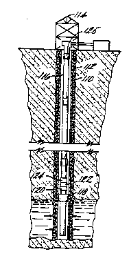
Referring to FIGURE 10, a production well (i.e., completed well) 110' enclosed
by a casing 112' with a rig 114' at the surface is generally shown, such being well
known in the art. Production tubing 116' is installed in well 110', also as is well
known. The lower end of production tubing 1 16' is perforated to provide a path for the
flow of oil from the ll.ydlu~,_bull bed up the center of the production tubing. A packer
118' is provided to isolate this lower end from the upper portion of the well. Sensors
120' are provided to monitor downhole parameters (such as pressure. ~ u~l~Lul~, flow,
gas influx, etc.) and elc~,LI~ devices 122' include, e.g., a sliding sleeve or
packer, a valve or pump or other fluid flow devices for control. A coil tubing 200 is
extended down the opening of the production tubing as is well known in the art. An
uphole acoustic tool 202 (e.g., an acoustic receiver, for example, an ~c.,CI.,lu~ ,L~l) and
a downhole acoustic tool 204 (e.g., an acoustic transmitter, for example a 1~ . l, ;c
device) are provided on coil tubing 200 for acoustic telemetry in accordance with this
alternate l mhol1im~ nt lt will be appreciated that two-way acoustic ... ,.. " ", ... ;~ Al ;on is
within the scope of the present invention, e.g., ri~ 7nrl~ctrir tl~la~ uphole and
downhole. It will further be appreciated that coil tubing is also employed while drilling
wo 96124751 ~Cr/US96JD1819
2~
-13-
a borehole, and acoustic telemetry as described herein may be applied such coil tubing.
Also, the acoustic telemetly of the present invention, as applied to coil tubing, may be
applied to other continuous tubing strings, e.g., chemical injection tubing, a dewatering
string and the like. Sensors 206 are also provided downhole on coil tubing 200 or in
the production well or production tubing, as is also well known in the art. Sensors 206
are connected to acoustic tool 204 for telemetry uphole.
As described in the earlier embodiment, at the surface a computer loaded with
software and a data acquisition and processing downhole modules are employed. The
software performs the control functions required for the transfer of data from the data
acquisition module to the processor module and performs the data processing and
v~k~uvl~d routines to assure that all tasks are executed in the proper priority sequence
(e.g., decoding, display, and storage). Surface equipment further includes a phone or
satellite based modem for ila ~ data between the production well site and a
remote facility using phone lines, and/or satellite ~ ~ .., .., .., ., :. -: ;. " .
The use of the coil tubing itself as the medium for acoustic telemetry is an
important feature of the present invention.
Referring to FIGURE 11, a production well (i.e., completed well) 110" enclosed
by a casing 112" with a rig 114" at the surface is generally shown, such being well
known in the art. Production tubing 116" is installed in well I 10", also as is well
known. The lower end of production tubing 116" is perforated to provide a path for the
flow of oil from the lIrVIV~aIbVI1 bed up the center of the production tubing. A packer
118" is provided to isolate this lower end from the upper portion of the well. Sensors
120" are provided to monitor downhole parameters (such as pressure, t~ ,u~la~
flow, gas influx, etc.) and elc ~ ,; rl devices 122" include, e.g., a sliding sleeve
or packer, a valve or pump or other fluid flow devices for control. Such sensors and/or
clc~ .f.. 1~ devices may be mounted downhole irl the production well itself
and/or ill~,vl,uula~v into the production tubing, as are well known. A downhole
acoustic ..., ., .. " ... ;. ~ .. tool 220 in accordance with an altemate embodiment of the
present invention is provided for acoustic telemetry. Acoustic tool 220 is integral to
casing 112" and is constructed to operate over depths, pressures and l~ a~
WO 96/24751 PCT/US96101819
? 1 87 423
-14-
commonlyfound inadownhole CllV;IUIIII.,II~. Acoustictool 220 similarto tool 124
(FIGURE 7) with the exception that the rotary ..,." ~;..,.c are attached to the casing
whereby the tool forms a part of the casing with the opening Ill~lcLLIuu~;ll forming part
ofthe completed well. An uphole acoustic ~...""""~; .-:;".. tûol 221 is provided for
acoustically ~ with downhole tool 220, and may a similar tyype tool.
The use of the casing itself as the medium for acoustic telemetry is am important
feature of the present invention.
Referring to FIGURE 12, a production well (i.e., completed well) 110"'
enclosed by a casing 112"' with a rig 114"' at the surface is generally shown, such
being well known in the art. Production tubing 116"' is installed in well 110"', also as
is well known. The lower end of production tubing 116"' is perforated to provide a
path for the flow of oil from the lly~Lucall)ull bed up the center of the production
tubing. A packer 118"' is provided to isolate this lûwer end from the upper portion of
the well. Sensors 120"' are provided to monitor downhole parameters (such as
pressure, ~lllp~a~ul~, flow, gas influx, etc.) and ~IC~L~ devices 122"'
include, e.g., a sliding sleeve or packer, a valve or pump or otber fluid flow devices for
control. Such sensors and/or ~1~.,1.~.". l, , l devices may be mounted downhole in
tbe production well itself and/or incorporated into the production tubing, as are well
known. A downhole acoustic ~ "", ~ " tool 222 in accordance with an alternate
rllli,ù,l;.ll. .. 1 ofthe present inventiûn is provided for acoustic telemetry. Acoustic tool
222 is coupled to casing 112" ', coupling of tools to the casing being well known in the
art, and is constructed depths, pressures and ~ la~uuc~ commonly found in a
downhole ~1l vilullulcllL. Acoustic tool 222 is similar to tool 24 (FIGURE 7) with the
exception of the coupling to the casing whereby the opening through the tool forming
2~ part ofthe completed well. An uphole acoustic . . ."",,.. ,;. ~1;.,,, tool 223 is provided for
acoustically ~ . " " " " ~ with downhole tool 222, and may a similar type tool.
The use of the casing itself as the medium for acoustic telemetry is an important
feature of the present invention.
Wo 96124751 2 1 8 7 4 2 3 PCr/USs6JD18~9
-15-
- While preferred l~mhotiim~ntc have been shown and described, various
~r~iifir:lti~nc and ~llhctitllfir,nc may be made thereto without departing from the spirit
and scope of the invention. Accordingly, it is to be understood that the presentinvention has been described by way of illllct~firnc and not limitation.
What is claimed is: