Sélection de la langue

Search

Sommaire du brevet 2187594 

Énoncé de désistement de responsabilité concernant l'information provenant de tiers

Une partie des informations de ce site Web a été fournie par des sources externes. Le gouvernement du Canada n'assume aucune responsabilité concernant la précision, l'actualité ou la fiabilité des informations fournies par les sources externes. Les utilisateurs qui désirent employer cette information devraient consulter directement la source des informations. Le contenu fourni par les sources externes n'est pas assujetti aux exigences sur les langues officielles, la protection des renseignements personnels et l'accessibilité.

Disponibilité de l'Abrégé et des Revendications

L'apparition de différences dans le texte et l'image des Revendications et de l'Abrégé dépend du moment auquel le document est publié. Les textes des Revendications et de l'Abrégé sont affichés :

  • lorsque la demande peut être examinée par le public;
  • lorsque le brevet est émis (délivrance).
(12) Brevet: (11) CA 2187594
(54) Titre français: TONDEUSE A CHEVEUX
(54) Titre anglais: HAIRCUTTING DEVICE
Statut: Périmé et au-delà du délai pour l’annulation
Données bibliographiques
(51) Classification internationale des brevets (CIB):
  • B26B 19/00 (2006.01)
  • A45D 44/00 (2006.01)
  • B26B 19/44 (2006.01)
(72) Inventeurs :
  • LIN, SHIH-WEI (Taïwan, Province de Chine)
(73) Titulaires :
  • SHIH-WEI LIN
(71) Demandeurs :
  • SHIH-WEI LIN (Taïwan, Province de Chine)
(74) Agent: BULL, HOUSSER & TUPPER LLP
(74) Co-agent:
(45) Délivré: 1999-05-04
(22) Date de dépôt: 1996-10-10
(41) Mise à la disponibilité du public: 1998-04-10
Requête d'examen: 1996-10-10
Licence disponible: S.O.
Cédé au domaine public: S.O.
(25) Langue des documents déposés: Anglais

Traité de coopération en matière de brevets (PCT): Non

(30) Données de priorité de la demande: S.O.

Abrégés

Abrégé français

Appareil pour la coupe de cheveux comportant un boîtier avec une première ouverture à sa partie inférieure. Un corps est monté à l'intérieur du boîtier et présente une deuxième ouverture à sa partie inférieure, laquelle est en communication avec la première ouverture. Un mécanisme pour la coupe de cheveux est monté à la partie inférieure du corps, au-dessus de la deuxième ouverture. Un dispositif d'aspiration est monté à l'intérieur du boîtier, avec conduit d'aspiration à la partie inférieure du boîtier et au-dessus du mécanisme de coupe. Le conduit d'aspiration aspire l'air du boîtier à travers la première et la deuxième ouvertures.


Abrégé anglais


A haircutting device includes a housing having a first
opening defined in an underside thereof. A body is
adjustably mounted in the housing and has a second opening
defined in an underside thereof and communicating with the
first opening. A haircutting mechanism is mounted on the
underside of the body and located above the second opening.
A suction member is mounted in the housing and includes a
suction vent defined in an underside thereof and located
above the haircutting mechanism. The suction member is
operated to draw air from the housing through the first and
second openings into the suction vent.

Revendications

Note : Les revendications sont présentées dans la langue officielle dans laquelle elles ont été soumises.


CLAIMS
1. A haircutting device comprising:
a housing defining a first opening in an underside thereof;
a body adjustably mounted in said housing and defining a second opening in an underside
thereof and communicating with said first opening;
a haircutting mechanism mounted on the underside of said body and located above said
second opening, said haircutting mechanism comprising:
a base plate mounted on the underside of said body;
a lower cutting piece fixedly mounted on said base plate and having a plurality of first blades
located above said second opening, and a threaded hole defined in said lower cutting piece;
an upper cutting piece slidably mounted on said lower cutting piece and having a plurality of
second blades located above said plurality of first blades, and an elongate slot defined in said
upper cutting piece and communicating with said threaded hole of said lower cutting price;
a pressing plate mounted on said upper cutting piece and defining a bore therein which
communicates with said elongate slot;
a positioning bolt extending through said bore and said elongate slot, and threadedly engaged
with said threaded hole; and
a biasing member mounted between said positioning bolt and said pressing plate; and
a suction member mounted in said housing and including a suction vent defined in an
underside thereof and located above said haircutting mechanism, said suction member being

operated to draw air from said housing through said first and second openings and into said
suction vent.
2. The haircutting device in accordance with claim 1, wherein said haircutting
mechanism further comprises:
a positioning plate fixedly mounted on the underside of said body and located adjacent to said
base plate;
a guiding block fixedly mounted on said positioning plate and having a dovetail-shaped
groove laterally defined therein;
a sliding plate slidably mounted on said positioning plate, a dovetail-shaped extension
extending from a first side of said sliding plate and slidably mounted in said dovetail-shaped
groove;
an upright arm extending from a second side of said sliding plate, a rod horizontally
extending from said upright arm; and
an upright wall extending from said upper cutting piece and located adjacent to said upright
arm, an arcuate slot defined in said upright wall for receiving said rod therein.
3. The haircutting device in accordance with claim 2, wherein said sliding plate defines
an elongate slot therein, said haircutting mechanism further comprising a motor fixedly
mounted in said body, a rotary disk rotatably mounted on an underside of said motor an
upright rod fixedly mounted on a periphery of said rotary disk to rotate therewith and slidably
received in said elongate slot.
4. The haircutting device in accordance with claim 1, wherein said body has a first side
wall and a second side wall, a groove transversely defined in the first side wall of said body, a
plurality of teeth formed on and extending inwardly from the second side wall of said body,
said base plate having a rib formed on a first end thereof and pivotally received in said

groove, and having an adjusting rod formed on a second end thereof and detachably retained
by one of said plurality of teeth.
5. A haircutting device in accordance with claim 4, wherein a plurality of indents are
defined in at least one of the first and second side walls of said body, and said housing
includes a hook formed on and extending inwardly from one side wall thereof and snapped in
one of said plurality of indents.

Description

Note : Les descriptions sont présentées dans la langue officielle dans laquelle elles ont été soumises.

21 87594
,~ 1 --
1 HAIR~ulLl~G DEVICE
2 The present invention relates to a haircutting device.
3 Scissors, clippers and the like are usually used as
4 haircutting implements for cutting and trimming a person~s
s hair. However, hair that has been cut by the haircutting
6 implements directly falls onto the floor or onto the
7 person's neck, thereby easily causing an uncomfortable
8 sensation to the person and an inconvenience in disposal of
9 the cut hair.
In accordance with one aspect of the present invention,
11 there is provided a haircutting device comprising a housing
12 having a first opening defined in an underside thereof. A
13 body is adjustably mounted in the housing and has a second
14 opening defined in an underside thereof and communicating
with the first opening.
16 A haircutting mechanism is mounted on the underside of
17 the body and located above the second opening. A suction
18 member is mounted in the housing and includes a suction vent
19 defined in an underside thereof and located above the
haircutting mechanism. The suction member is operated to
21 draw air from the housing through the first and second
22 openings into the suction vent.
23 In the drawings:
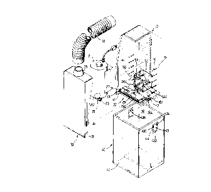
24 Fig. 1 is a pérspective view of a haircutting device in
accordance with the present invention;
26 Fig. 2 is a partially cut-away exploded view of Fig. 1;
27 Fig. 3 is an enlarged exploded view of a cutting
28 mechanism;
29

2 1 87594
2--
1 Fig. 4 is a side cross-sectional view of Fig. 1;
2 Fig. 5 is a front plan cross-sectional view of Fig. 1;
3 Fig. 6 is an operation view of Fig. 5;
4 Fig. 7 is a top plan cross-sectional view of Fig. 1;
Fig. 8 is a front plan cross-sectional view of Fig. 1,
6 showing the cutting m~chanism being disposed in an inclined
7 manner; and
8 Fig. 9 is a cross-sectional view showing an engagement
9 between a snapping member and an indent.
Referring to the drawings, and initially to Figs. 1 and
11 2, a haircutting device according to the present invention
12 comprises a housing 40 having a first opening 42 defined in
13 an underside thereof. A hollow body 10 is adjustably mounted
14 in the housing 40 and has a second opening 12 defined in an
underside thereof and communicating with the first opening
16 42. A haircutting mechanism 20 is mounted on the underside
17 of the body 10 and is located above the second opening 12.
lB A suction member 30 is securely coupled with the body 10 and
19 is adjustably mounted in the housing 40.
Preferably, the body 10 has two side walls each having
21 a groove 14 vertically defined therein. The suction member
22 30 has two side walls each having a rib 33 vertically formed
23 thereon and received in an associated groove 14 such that
24 the suction member 30 can be coupled with the body 10.
Referring to Figs. 2 and 3, the haircutting mechanism
26 20 comprises a base plate 26 mounted on the underside the
27 body 10. A lower cutting piece 27 is fixedly mounted on the
28 base plate 26 and has a plurality of first blades 272
29

2t 87594
- 3 -
1 located above the second opening 12. A hole 276 is defined
2 by a threaded periphery of the lower cutting piece 27.
3 An upper cutting piece 28 is slidably mounted on the
4 lower cutting piece 27 and has a plurality of second blades
281 located above the plurality of first blades 272. An
6 elongate slot 283 is ~efined in the upper cutting piece 28
7 and aligns with the hole 276. An upright wall 284 extends
8 from one side of the upper cutting piece 28 and has an
9 arcuate slot 285 defined therein.
A pressing plate 292 is mounted on the upper cutting
11 piece 28 and has a bore 293 defined therein and aligning
12 with the elongate slot 283. A positioning bolt 29 extends
13 through the bore 293 and the elongate slot 283, and is
14 securely engaged in the hole 276. A biasing member 294 is
mounted between the positioning bolt 29 and the pressing
16 plate 292.
17 Referring to Figs. 2-6, a transmission mechanism 50
18 includes two supporting blocks 56 each having a first end
19 fixedly mounted on each of the two side walls of the body 10
and a second end with an arcuate head 562. A pivot bracket
21 is received in the body 10 and includes two side plates 53
22 each pivotally mounted on the second end of each of the two
23 supporting blocks 56.
24 - Preferably, each of thé two side plates 53 has an
arcuate groove 532 defined therein for receiving the arcuate
26 head 562 of each of the two supporting blocks 56.
27 An upper plate 51 has an elongate slot 512 defined
28 therein and two distal ends each pivotally engaged with an
29

21 875q4
~_ _ 4 -
1 upper end of each of the two side plates 51. A lower plate
2 52 has two distal ends each pivotally engaged with a lower
3 end of each of the two side plates S1. A linking rod 55
4 extends from the lower plate 52 and is received in the
arcuate slot 285.
6 A motor 21 is fiYedly mounted in the body 10. A rotary
7 shaft 212 is rotatably mounted on an underside of the motor
8 21. A rotary disk 22 is fixedly mounted on the rotary shaft
9 212. An upright rod 23 is fixedly mounted on a periphery of
the rotary disk 22 to rotate therewith, and is slidably
11 received in the elongate slot 512 and urged on a periphery
12 defining the elongate slot 512.
13 In operation, referring to Figs. 5-7 with reference to
14 Figs. 2 and 3, the rotary disk 22 can be driven by the motor
21 to rotate the upright rod 23 which can slide in the
16 elongate slot 512 and urge on the periphery defining the
17 elongate slot 512 so as to move the upper plate 51 and the
18 lower plate 52 from a position as shown in Fig. 5 to a
19 position as shown in Fig. 6, thereby moving the upright wall
284 by means of the rod 55 retained in the arcuate slot 285
21 so as to move the upper cutting-piece 28 relative to the
22 lower cutting piece 27.
23 Referring to Fig. 8 with reference to Figs. 2 and 3,
-24 the body 10 has a first side wall and a second side wall.
An arcuate groove 13 is defined in an underside of the first
26 side wall of the body 10. A cavity 17 is defined in the
27 second side wall of the body 10. A plurality of teeth 182
28 extends inwardly from the second side wall of the body 10
29

21 87594
~ -- 5
1 and are located adjacent to the cavity 17.
2 The base plate 26 has an arcuate rib 262 formed on a
3 first end thereof and pivotally received in t-he arcuate
4 groove 13, and has an adjusting rod 264 formed on a second
end thereof and detachably retained by one of the plurality
6 of teeth 182.
7 By such an arrangement, the base plate 26 can be
8 pivoted relative to the first side wall of the body 10,
9 thereby adjusting an inclination angle of the base plate 26.
Referring to Figs. 2 and 9, a plurality of indents 16
11 are defined in the two side walls of the body 10, and a
12 plurality of graduations 19 are formed on the two side walls
13 of the body 10 and each align with each of the indents 16
14 respectively.
The housing 40 includes two side walls each having a
16 snapping member 43 formed thereon. The snapping member 43 is
17 formed by defining two opposite U-shaped cavities 430 in
18 each of the two side walls of the housing 40, thereby
19 forming an upper end 434 with a hook 436 extending inwardly
therefrom, a lower end 432, and two webs 44 for connecting
21 the snapping member 43 to the side wall of the housing 40.
22 Each of the hooks 436 can be snapped in one of the
23 plurality of indents 16 and also can be detached from the
24 associated indent 16 by pressing the lower end 432 such that
the body 10 can be adjustably mounted in the housing 40.
26 Referring to Figs. 2 and 4, the suction member 30 has a
27 chamber 32 defined therein and a suction vent 31 defined in
28 an underside thereof and located above the upper and lower
29

21 87594
~_ - 6 -
1 cutting pieces 28 and 27.
2 The suction member 30 also includes a connector 35
3 formed on an upperside thereof and connected with a hose 36
4 which is attached to a suction device such as a vacuum
cleaner (not shown) and the like, thereby being able to draw
6 air from the housing 40 into the chamber 32 via the suction
7 vent 31 and the second opening 12.
8 By such an arrangement, especially referring to Fig. 4,
9 the haircutting device can be used to cutting and trimming a
person's hair 60 with the first opening 42 of the housing 40
11 disposed above his/her hair.
12 Then, the suction member 30 can be operated by the
13 vacuum cleaner so as to draw hair 60 upwardly into the
14 second opening 12. The upper cutting piece 28 can then be
operated by the motor 21 to move relative to the lower
16 cutting piece 27, thereby cutting hair 60 drawn through the
17 second opening 12, and the cut hair can be drawn into the
18 chamber 32 via the suction vent 31 and then taken away by
19 the vacuum cleaner via the hose 36.
21
22
23
24 -- .
26
27
28
29

Dessin représentatif
Une figure unique qui représente un dessin illustrant l'invention.
États administratifs

2024-08-01 : Dans le cadre de la transition vers les Brevets de nouvelle génération (BNG), la base de données sur les brevets canadiens (BDBC) contient désormais un Historique d'événement plus détaillé, qui reproduit le Journal des événements de notre nouvelle solution interne.

Veuillez noter que les événements débutant par « Inactive : » se réfèrent à des événements qui ne sont plus utilisés dans notre nouvelle solution interne.

Pour une meilleure compréhension de l'état de la demande ou brevet qui figure sur cette page, la rubrique Mise en garde , et les descriptions de Brevet , Historique d'événement , Taxes périodiques et Historique des paiements devraient être consultées.

Historique d'événement

Description Date
Le délai pour l'annulation est expiré 2001-10-10
Lettre envoyée 2000-10-10
Accordé par délivrance 1999-05-04
Inactive : Taxe finale reçue 1999-02-03
Préoctroi 1999-02-03
Un avis d'acceptation est envoyé 1998-10-09
Lettre envoyée 1998-10-09
Inactive : Renseign. sur l'état - Complets dès date d'ent. journ. 1998-10-05
Inactive : Dem. traitée sur TS dès date d'ent. journal 1998-10-05
Inactive : Approuvée aux fins d'acceptation (AFA) 1998-09-10
Demande publiée (accessible au public) 1998-04-10
Exigences pour une requête d'examen - jugée conforme 1996-10-10
Toutes les exigences pour l'examen - jugée conforme 1996-10-10

Historique d'abandonnement

Il n'y a pas d'historique d'abandonnement

Taxes périodiques

Le dernier paiement a été reçu le 1998-09-29

Avis : Si le paiement en totalité n'a pas été reçu au plus tard à la date indiquée, une taxe supplémentaire peut être imposée, soit une des taxes suivantes :

  • taxe de rétablissement ;
  • taxe pour paiement en souffrance ; ou
  • taxe additionnelle pour le renversement d'une péremption réputée.

Les taxes sur les brevets sont ajustées au 1er janvier de chaque année. Les montants ci-dessus sont les montants actuels s'ils sont reçus au plus tard le 31 décembre de l'année en cours.
Veuillez vous référer à la page web des taxes sur les brevets de l'OPIC pour voir tous les montants actuels des taxes.

Historique des taxes

Type de taxes Anniversaire Échéance Date payée
TM (demande, 2e anniv.) - petite 02 1998-10-13 1998-09-29
Taxe finale - petite 1999-02-03
TM (brevet, 3e anniv.) - petite 1999-10-11 1999-09-24
Titulaires au dossier

Les titulaires actuels et antérieures au dossier sont affichés en ordre alphabétique.

Titulaires actuels au dossier
SHIH-WEI LIN
Titulaires antérieures au dossier
S.O.
Les propriétaires antérieurs qui ne figurent pas dans la liste des « Propriétaires au dossier » apparaîtront dans d'autres documents au dossier.
Documents

Pour visionner les fichiers sélectionnés, entrer le code reCAPTCHA :


Pour visualiser une image, cliquer sur un lien dans la colonne description du document. Pour télécharger l'image (les images), cliquer l'une ou plusieurs cases à cocher dans la première colonne et ensuite cliquer sur le bouton "Télécharger sélection en format PDF (archive Zip)" ou le bouton "Télécharger sélection (en un fichier PDF fusionné)".

Liste des documents de brevet publiés et non publiés sur la BDBC .

Si vous avez des difficultés à accéder au contenu, veuillez communiquer avec le Centre de services à la clientèle au 1-866-997-1936, ou envoyer un courriel au Centre de service à la clientèle de l'OPIC.


Description du
Document 
Date
(aaaa-mm-jj) 
Nombre de pages   Taille de l'image (Ko) 
Description 1999-05-02 6 229
Dessin représentatif 1999-04-27 1 25
Abrégé 1997-03-03 1 20
Abrégé 1997-03-03 6 229
Revendications 1997-03-03 4 129
Dessins 1997-03-03 9 230
Dessin représentatif 1998-04-23 1 11
Revendications 1998-08-11 3 88
Rappel de taxe de maintien due 1998-06-10 1 111
Avis du commissaire - Demande jugée acceptable 1998-10-08 1 163
Avis concernant la taxe de maintien 2000-11-06 1 178
Correspondance 1999-02-02 1 46
Taxes 1998-09-28 1 38
Taxes 1999-09-23 1 35