Note : Les descriptions sont présentées dans la langue officielle dans laquelle elles ont été soumises.
WO 95128190 2187769 PCT/US95/04527
SYSTEMS AND ML''TfIO S FOR CASSETTE TD NTTFTCLTTtIN
FOR DRUG PUMPS
Field of the Invention
The present invention relates generally to
drug pumps for pumping fluid to a patient. More
particularly, the present invention relates to systems
and methods for identifying attachable fluid cassettes
which supply fluid to the drug pump for pumping to the
patient.
--- Background of the Invention
Various drug pumps are known for pumping fluid
to a patient in connection with treatment of various
medical conditions. Drug pumps are known which include
a reusable control module with-a disposable or reusable
fluid reservoir cassette wherein the reservoir is either
self-contained with the cassette or remote from the
cassette. The control module pumps fluid from the
cassette to the patient when the cassette is attached or
mounted to the control module.
There is a need for using the control module
in connection with different fluid reservoir cassettes.
The cassettes may differ in the nature of the drugs or
other fluid contained therein. Other differences might
relate to the manner in which the fluid reservoir
component cooperates with the control module to deliver
the fluid to the patient. For example, the control
module may include a pumping mechanism which engages a
tube extending from the fluid reservoir cassette. The
fluid reservoir cassettes may have variations in tubing
size. In thatcase, it is important to identify to the
R'O 95/28190 21 8 7 7 6 9 PCT1US95l04527 =
2
control module the size of the tubing attached to the
fluid reservoir cassette so-.that the proper amount-of
drug is delivered to the patient.
-
There-is also a need for identifying a proper
cassette from an improper-cassette mounted to the
control module. In some cases; the control module inay
be programmed or configured:to pump fluidin a certain
therapy from a particular cassette. If an improper
cassette is mounted to the control module, there is a
danger the patient may be given an improper-drug.
There has arisen a need for systems and
methods for identifying a fluid reservoir cassette which
mounts to a control module of a drug pump.
Summarv of the Invention -
- The present invention relates to a pump
including a control module having a dbntrol system with
a processor and associated memory for controlling
operation of--the pump. Thecontrol system also includes
a pumping mechanism for pumging_fluid which is
controlled by the processor. A fluid reservoir or
cassetteis selectively mountable to.the control module.
The fluid reservoir includes indiciafor ideritifying a
property ofthe fluid cassette such as tube size, drug
type, or other_ The control system includes structure
for identifying the indicia=associated with the fluid
cassette_ The structure for identifying indicia sp-nds a
signal to the processor indicative of the irndicia
sensed. An-appropriate signal is generatedfor
WO 95/28190 2 3 8 7 7 6 9 pCTfUS95/04527
3
controlling the pumping mechanism or other pump functioa
based upon the indicia identified. If an improper
cassett-e,is sensed, then a pump disabling program
disables the pump mechanism from pumping even though the
operator attempts to initiate_.the pumping operation.
In one preferred embodiment, the reservoir
includes a base plate and a tube extending from the
fluid reservoir which is interconnectable to the
patient. The control module includes a pumping
mechanism which engages the tube during pumping to move
fluid from the reservoir to the patient.
There are various different indicia which may
be provided on the base plate to identify a property of
the_reservoir. The base plate may include one or more
projections. The structure for identifying indicia may
include a force sensitive resistor mounted to the
control module for engaging the projection on the base
plate. The force sensitive resistor generates a signal
for the processor of the control system.
Alternatively, the structure for identifying
indicia may include a microswitch mounted to the control
module which engages the projection on the base plate
and sends a signal to the processor of the control
system.
- A further alternative for the structure for
identifying indicia may include a slotted optical sensor
and a reciprocally mounted plunger. The slotted optical
sensor and the plunger are mounted to the control
W 95128190 2 i 8 7 7 6 9 PCT1U895/04527
4
module. The plunger is engaged by the projection to
move the projection relative to the optical sensor. The-
optical sensor generates a signal for the processor of
the control system indicative_of the change in position
S of the plunger. In-another alternative embodiment, the --
structure for identifying indicia may include a
reciprocally mounted plunger which makes or breaks
electrical connection between electrical contacts during
engagement by the projection of the base plate. This
electrical connection or disconnection generates a--
signal for the processor.
Instead of a mechanical interaction between
indicia on the base plate and the structure for -
identifying the indicia associated with the control.
module, optics may be utilized wherein no contact
between the control module and the cassette occurs with
respect to the indicia'identification structure. In one
embodiment, the control module includes a light emitter
for directinglight toward thebase plate. The indicia
on the base plate includes an appropriately located.
prism arrangement for reflecting the light back toward
the control module. The structure for i-dentifying
indicia further includes a light receiver for receiving
the light reflected from the prism arrangement
associated with the base plate and sending a.signal to
the processor_
Alternatively, the structure for identifying
WO 95128190 _-'2 i87 7 6 9 PCT/US95/04527
indicia-may include a light emitter for directing light
toward the base plate and the base plate may include a
reflective patch for reflecting the light back toward
the control module. The structure for identifying
5 indicia further includes a light receiver for receiving
the light reflected from the reflective patch and
sending a signal to the processor.
Other cassette identification systems are
usable including those relating to capacitive switches,
Hall effect switches, reed switches, inductive switches,
piezoelectric switches, magneto-resistive switches, and
other non-contact switches. Acoustic switches are also
usable. Also, optical print sensors may also be
utilized for reading bar code information or the like
printed on the cassette. Laser positioning sensors may
be utilized where the height of a projection extending
from the base plate is measured to identify the
cassette: -
The pump may include a display interconnected
to the processor of the control system. Appropriate
display programs are associated with the processor for
generating an appropriate display depending on the
cassette sensed by the control module. The pump
apparatusmay include an audible signal device for
generating an-appropriate audible signal when the
control module has identified either a correct cassette
or an incorrect cassette. Visual signals, such as a
green and/or red LED, may be provided with the pump to-
WO 95/28190 21 g 7' 69 PCT1US95/04527 =
6
indicate the appropriateness of the cassette sensed.
Drief Describtion of the Drawings
Figure i.,.is a schematic diagram of a pump
apparatus according to thepresent invention, showing a
self-contained fluid cassette separated from the control
module.
Figure LA is a schematic diagram of a remote -
reservoir adapter and remote fluid reservoir useable
with the control module of Figure 1.
Figure 2 is a schematic diagram of the control
system of the control module shown in Figure 1.
Figure 3 is a-first cassette identification
system including a plurality of force-sensitive -
resistors.--
Figure 4-is a second alternative cassette_
identification system including a force-sensitive
resistor and an elastomer.
Figure 5 is a third alternative cassette
identification system including a force-sensitive
resistor and a coil spring.
Figure 6 is a fourth alternative cassette
identification system including a force-sensitive
resistor and a flexible beam.
Figure 7 is a fifth alternative cassette-_
identification system including a prism arrangement:
Figure 8 is a cross-sectional-view of the
identification system shown in Figure 7takenalong
lines 8-8.
= WO 95128190 2 1 8 7 769 pCT/US95/04527
7
Figure 9 is a view of the light emitter of the._
cassette identification-system shown in Figures 7 and 8.
Figure 10 is a sixth alternative cassette
identification system including an alternative prism
arrangement.
Figure 11 is a seventh alternative cassette
identification system including a reflective patch.
Figure 12-is ari eighth alternative cassette
identification system including a microswitch.
Figure 13 is a ninth alternative cassette identification
system including a reciprocally mounted plunger with an
electrical contact thereon.
Figure 14 is a tenth alternative cassette
identification system including a slotted optical sensor
and a reciprocally mounted plunger.
Figure 15 is a side view of the cassette
identification system shown in Figure 14, showing three
slotted optical sensors and three_.reciprocally mounted
plungers..
Figure 16 is a second alternative plunger
arrangement to the arrangement shown in Figures 14 and
15. -
Figure 17 is a third alternative plunger
arrangement to the arrangement shown in Figures 14 and
15.
Figure 18 is a fourth alternative plunger
arrangement to the arrangement shown in Figures 14 and
15. --
WO 95/28190 218 7 7 6 9 pCT/US95/04527 =
8
Figure 19 is a fifth alternative plunger
arrangement to the arrangement shown in Figures 14 and --
15. -
Figure 20 is a sixth alternative plunger
arrangement to the arrangement shown in Figures 14-and
15.
Figures 21-29 illustrate one preferred -
cassette identification system. Figures 21-23, 26, 27
and 29 show a control module and a first cassette.-
Figures 24 and 25 show a second cassette. Figure 28
shows a third cassette. --
Detailed Descriution of the Preferxed Embodiments
Thepresent invention relates to systems and
methods for automatically identifying a cassette mounted
to a control module of a fluid pumping system, such as a
drug infusion system. The identification system can
identify indicia on the cassette relating to the type of
drug,-the concentration o~.-the drug, the volume ofthe
fluid reservoir, or the amount of d.rug pumped per
activation of the pump, i.e., tube size. Such
information is important to safeand effective drug
therapy. When the information is entered automatically
to the control module, such-as with-the indicia -
identifying system, a saferand-more effective system
results. There-is less chance for human error, as would ---
be the case if such information were-entered manually.
Also, the indicia-identifying system can be used to
prevent operation of the pump if an unauthorized - -
WO 95128190 ~ 1 817 6 9 PCT/US95/04527
9
cassette is attached.
Various cassettes are provided to be
identified by the control module. The control module
identifies the cassettes in one of a variety of manners,
including engagement with a projection on the.cassette
or sensing optical signals or the absence of optical
signals due to the presence of the cassette. Other
structures and methods are provided to identify the
cassettes.
Referring now to Figure1, a pump apparatus or
pump 20 is shown. Pump 20 includes a control module 24
and a separate self-contained fluid cassette 26 which is
mountable to the control module 24. Control module 24
is reusable. Cassette 26 may be disposable, or in some
cases reusable after refilling. As will be discussed
below in greater detail, cassette 26 can be configured
as a remote reservoir adapter linking a remote fluid
reservoir to control-module 24. -
One lock/latch mechanism for mounting cassette
26 to control 24 includes one or more hooks 45 which
each engage a rod 46 mounted to control module 24. Loop
47 is grasped by loop engaging device 48_to releasably
hold cassette 26 in place with hook 45 around rod 46.
Other lock/latch mechanisms are anticipated for holding
cassette 26 adjacent control module 24 tofacilitate
operation.
Control module 24 includes a pumping mechanism
28 which pumps fluid from cassette 26. Cassette 26
CA 02187769 2004-11-29
WO 95/28190 PCT/US95{04527
includes a fluid reservoir 30 with a compressible tube
32 extending therefrom. Tube 32 is interconnectable to
the patient. Cassette 26 includes a base plate or
pressure plate 34 having a top surface facing control
5 module 24. Tube 32 is positionable between base plate
34 and pumping mechanism 28. Pumping mechanism 28
includes reciprocally mounted members which engage tube
32 in a particular manner to move fluid through tube 32.
In one preferred embodiment, pumping mechanism 28
10 includes a reciprocally mounted inlet valve, a
reciprocally mounted outlet valve, and a reciprocally
mounted expulsor. The expulsor pushes fluid through the
tube 32. The inlet and outlet valves, on opposite sides
of the expulsor, open and close the tube to permit the
passage of fluid through the tube 32. Pumping mechanism
28 includes a rotatable cam shaft controlled by a motor
which moves the inlet and outlet valves and the expulsor
in the appropriate manner. Base plate 34 and outer
housing 44 cooperate to enclose reservoir 30 in Figure
1. An example of one pumping mechanism useable in pump
20 is shown in U.S. Patent No. 4,559,038.
Control module 24 further includes a plurality
of keys 36 for providing input.structure for the
operator to input information into control module 24.
Control module 24 also includes a display 38, such as an
LCD (liquid crystal display) for displaying information
to the operator. An audible signal device 56 may be
WO 95/28190 218 7 7 6 9 PCT/US95/04527
11-
provided to send an audible signal to the operator
indicative of various conditions of pump 20. For --
example, a beeper may be provided for audible signal
device 56. A visual signal device 58 may be provided
for sending a visual signal to the operator indicative
of various conditions of pump 20. For example, red and
green LED (light-emitting diodes) may be provided for
visual signal device 58.
Control module 24 includes a device 42 for
identifying indicia 40 on cassette 26. Various cassette
identification systems are anticipated including a
variety of different identifying devices 42 and indicia
40. -
Referring now to Figure 2, a control system 50
for control module 24 is shown. Control system 50
includes a processor-52 electrically interconnected to
keypad 36, display 38, pump mechanism 28, and indicia
identifying device 42. Audible signal device 56 and
visual signal device 58 are interconnected to processor
52. Control system 50 further includes a memory 54 for
storing various programs for operating pump 20. One
program to be stored in memory 54 is pump disabling
program for disabling pump mechanism 28 if an improper
cassette is sensed.
Figure 2 also shows a lock/latch sensor 60
interconnected to processor 52. Lock/latch sensor 60
senses when cassette 26 has been locked/latched to
control module 24 through the operator activated latch
WU 95/28190 2 1 8 7 7 6/ PCTIUS95/04527
12
structure 45, 46, 47, 48 which holds cassette 26
adjacent control module24. Figure_2further shows a
pressure sensor 62 interconnected to processor 52.
Pressure sensor 62 is utilized to seiise pressure in-tube
32. Pressure-sensor 62and~lock/latch sensor 60 ate
optional with respect to cassette identification.
However, these sensors are tised to advantage 3uring
cassette identification. These-sensors can be utilized -
by processor50 to identify if therehappens to be.a
malfunction of the cassette=identification system.
Processor 52-will know when-cassette-26 has been mountecl
to control module 24 by receipt of a lock/latch signal
and an appropriate pressure signal (i.e., a pressure
sensed within an acceptable operating range). At that
point, processor 52 can begin iooking for an appropriate
signal from theidentifying_device 42 for identifying
the indicia 40. If no identification signal is present,
processor 52 does not permit initiation or centinuation
of the pumping operation bypump mechanism 28.
Processor 52 may also send an appropriate error signal
to display 38, audible signal device 56, and/or visual
signal device 58. Processor 52 checks for a cassette
identification signal periodically or continuously.
Periodic is preferred as a manner of reducing energy
consumption of pump 20.
In Figure 2, the various sensors, switches,
and other components of control system 50 are
interconnected.to processor=52 through interconnection
WO 95/28190 2 1 8 7 7 6 9 PCT/US95/04527
13
link 64.
Referring now to Figure lA, a remote reservoir
adapter 26a is shown which is mountable to control
module 24 in a similar manneras cassette 26. However,
instead of including a self-contained fluid reservoir,
adapter 26a is separate from remote fluid reservoir 30a.
A tube 31a links remote fluid reservoir 30a to adapter
26a. Adapter 26a includes a base plate 34a with an
extending base or housing 44a, hooks 45a, and a loop
47a. Housing 44a is smaller than housing 44 typically
since no fluid reservoir is contained therein. Tube 32a
extends from adapter 26a to be linked to the patient.
As with respect to cassette 26, adapter 26a includes
identifying indicia 40a to permit identification by
control module 24.
In the following description of various
preferred embodiments, reference to cassette 26 is to be
interpreted as either cassette.26 of Figure 1 or adapter
26a of Figure lA.
Referring now to Figure 3, a first cassette
identification system 70 is shown including indicia
associated with cassette 26 and indicia identifying
structure associated with control-module 24. The
indicia on--cassette 26 includes a projection 84
projecting upwardly from top surface 86 of base plate
34. The indicia identifying structure on control module
24 includes a plurality of forde-sensitive resistors
(FSRs). FSR 72 senses contact by projection 84. FSR 72
WO 95128190 218 77 6 9 PCTIUS9S/04527
14
sends an appropriate signal through electrical
connection 78 to processor 52 of control system 50.
As shown in Figure 3, second FSR 74 and third
FSR 76 are not ehgaged by any projections extending from
cassette 26. Electrical connection-80 can send an -
appropriate signal from a second FSR 74 indicative-of a
condition where no-projection is sensed. Similarly,
electrical connection 82 can send a signal from third
FSR 76 indicative of no projection sensed.
- Cassette identificatiori system 70 is capable
of identifying at least three different cassettes 26.
System 70 is shown identifying a first cassette 26. A
second cassette could include a projection-appropriately
positioned to engage only second FSR 74. Similarly, a
projection could be provided in the appropriate position
to engage only third FSR 76. In this manner, a failure
of one of the FSRs to sense the presence of-a projection
does not give an erroneous signal.to proces5or 52..
If it is a desireable-to identify more than
three cassettes 26 utilizing only three FSRs, it is
possible to utilize the FSRs in a manner which -
identifies up toeight different cassettes_ However, it
is not possible to differentiate between cassettes if
one-or more of the FSRs would happerito_fail-to idesitify
a projection which is an engagement with thexespective
FSR, or-if one-of the projections is somehow damaged or
malformed such that no engagement occurs. When only
three different cassette sensors are provided, and only
WO 95/28190 2187769 PCT/US95104527
three cassettes are identified with them, then_only one
cassette projection is sensed. If no projection is
sensed, or if more than one projection is sensed, then
control module 24 recognizes an improper-or damaged
5 cassette has been attached. -
Referring now to Figure 4, a second
alternative cassette identification system 90 is shown.
Like system 70, system 90 includes FSRs. In Figure 4,
FSR 94 is shown for sensing projection 96 extending from
10 cassette 26. Compressible elastomer 92 is positioned
between base surface 91 of control module 24 and FSR 94.
Elastomer 92 provides a greater.range of variation with
respect to the height of projection 96 extending from
cassette 26 relative to control module 24. Without
15 elastomer 92, it may be possible for projection 96 to
damage FSR 94 if projection 96 happens to extend too far
from cassette 26 or-if projection 96 is pushed too far
into FSR 94. Similarly, if projection 96 does not
extend far enough, FSR 94 will not sense the presence of
projection 96 if there is insufficient contact below the
threshold-amount of the FSR or-if there is no contact at
all. Elastomer 92 extends the range of operation of FSR
94 such that variations in the height of projection 96
can be accommodated. Such accommodation is useful
during manufacturing because the ranges on the possible
height of projection 96 do not have to be as narrow as
they might if no elastonmer is present. Also, damage to
the FSR may be avoided if the projection is pushed into
WO 95/28190 218 7 7 6 9 PC'T/US95l04527
16
the FSR at some point during mountin_g or dismounting of
cassette 26.
Referring-now to Figure 5, a third alternative
cassette identification system 100 is shown. Instead of
an elastomer 92 in pystem 90, system 100 includes a coil_. ..
spring 104 which biases-FSR_102 away from base surface
101 of control module 24. FSR 102 sensee the presence
of projection 106 extending from cassette 26.. Spring
104 provides for an-extended range in the height of
projection 106 relative to control module 24. it will --
be appreciated that other.types of springs,such as
wavy, belleville and others-could be used instead of
coil spring 104. _
Referring now to Figure 6, a fourth -
alternative cassette identification system 110 is shown.
Instead of anelastomer 92 as in system 90,or a spring
104 as in system 100, system 110 includes a flexible
beam 114 extending from top surface 111,of control-
module 24. Flexible beam 114 positions FSR 112 at_a
spaced apart distance from top surface 111.FSR 112
senses the presence of projection 116. Flexible beam
114 accommodates variations in the extension-of
projection 116.relative to control fnodule.24.
Referring now to Figures 7-9, a fifth
alternative cassette.identification system 130 is shown.
Cassette 26-includes a prism arrangement 140 for
reflecting light from control module 24_.in an.. -
appropriate manner back toward control module 24 to
WO 95/28190 Z 187769 PCT/US95104527
17
identify cassette 26. Prism arrangement 140 includes a
top surface 142, a first prism surface 144, a second
prism surface146, and a top surface 148. Base plate 34
is constructed to include prism arrangement 140 with the
top surfaces 146, 148 forming a top surface portion of
base plate 34-and surfaces 144, 146 forming a bottom
surface portion of base plate 34._
Light emitter 132 emits light represented by
arrows 133 which enters prism arrangement 140 and is
reflected back toward control module 24. As shown in
Figure 7, prism arrangement 140 is reflecting light from
emitter-132 to receiver 134. Receiver 134 sends an
appropriate signal to processor 52_indicative of the
presence of prism arrangement 140 reflecting light to
receiver 134. Base plate 34 of cassette 26 is made from
a material which permits the passage of light from
emitter 132 to be reflected internally at surfaces 144
and 146. In one preferred embodiment, base plate 34 is
made from polycarbonate which has an index of refraction
of about 1.6 relative to air. Angles of 45 degrees
relative to the direction of light passage are utilized
for surfaces 144 and 146 in order to obtain sufficient
internal reflection to have receiver 134 sense light
being emitted from emitter 132. -
- To indicate the presence of a second cassette
different from cassette 26, prism arrangement 140 is
provided with a different_configuration. Receiver 136
is utilized instead of receiver 134. In order to have
WO 95/28190 218 7 7 6 9 PCTIUS95/04527
18
receiver 136 receive light from emitter 132, surface 146
is moved adjacent (belooi in Figure 7) receiver 136_
Surface.144 would remain in the same location that is
depicted in Figure 7. Receiver 136 would send an
appropriate signal to processor 52 indicative of the
presence of prism arrangement 140 reflecting light to
receiver 136.
To indicate the presence of a third cassette,
receiver 138 is utilized. In order to have_receiver 138
sense-light from emitter 132, surface 144 is positioned
in a reverse-direction to reflect light from emitter 132
toward receiver 138. Surface 146 is appropriately
positioned beneath receiver.138. I.in-this manner, three
different cassettes can be sensedby control module 24.
As shown in Figure 7, top surface-142 is
configured as a lens surface for columnating the light
from emitter 132. As shown in Figures 7 and s, top
surface 148 is also configured as a lens for focustng
the light passing through base plate 34 toward receiver - -
134.
Receivers 134,-=I36; 138 ca.n be any of a-
variety of light receivers which generate a signal-when
light is present. Receivars 134, 136, 138 may be
phototransistors, photodiodes, or photodarlingtons.
- - Referring toFigure 9, an example of an ---
emitter 132 is-shown in greater detail. Emitter 132 may
be an infrared emitting diode. An epoxy coating 154
encloses chip 156 which emits the infrared light.
WO 95/28190 21$ 7 76 9 pCT/US95/04527
19
Extending from emitter 132 are.two leads 150, 152 to
connect to processor 52. - -
In cassette identification system 130, a
comparitor circuit is useful for comparing the signals
from all three receivers 134, 136, 138. It is preferred
that the three receivers, 134, 136, 138-each generate a
signal, with one signal being strong and two being weak.
The comparitor circuit identifies the receiver with the
stronger signal as being the receiver positioned in the
appropriate manner relative to the prism arrangement 140
for identification of the cassette. -The two weaker
signals indicate that some light is reaching the
receivers, but that light is not intended to cause those
receivers to indicate the.presence of the prism
arrangement 140. The light that is being received by
receivers 136, 138 which generates the weaker signals
could come from emitter 132. Also, the light could come
from external of pump 20.
One preferred cassette identification system
130 may include a modulating signal with respect to
emitter 132- The light would preferably flash at a
frequency not commonly found in the environments where
pump 20 is to be used. This would increase the accuracy
of cassette identification system 130. The modulating
signal set.at the uncommon frequency would help reduce
inaccurate results caused by sunlight, room lighting, or
other lighting devices which produce light which could
hit pump 20, possibly causing an inaccurate reading of
WO 95/28190 2 18 7 7 6 9 pC'1'/US95/04527 =
the cassette identification system.
Referring now to Figure 10, a sixth
alternative cassetteidentification system 160 is shown.
Control module 24 in Figure 10 is similarly arranged as
5 control module 24 of Figures 7 and S. An emitter 162 is
provided for directing light toward cassette 26.
Cassette 26 includes structure for reflecting the light
back toward control module 24. In particular, base
plate 34 of cassette 26 includes a prism arrangement 170
10 which has a plurality of indentations. A first
indentation 171 includes a first prism surface 174: A
second indentation 175 provides a second prism surface
176. 7is shown in Figure 10, light, represented byarrow
177, is emitted by emitter 162, passes through top
15 surface 172 of=base-plate 34, and is reflected by first
prism surface 174 toward second prism surface 176.
Second prism surface 176 reflects the light back toward
receiver 164_..___ __ - ~- -
As shown in Figure 10, prism arrangement 170
20 is not directing light toward either second receiver 166
or third receiver 168. fihese receivers are'utilized to
identify different cassettes from cassette 26. A
different prism arrangement 170 would be provided--to
reflect light from emitter 162 to receiver 166. In
particular, indentation 175 and second prism surface-176. --
would-be positioned beneath second receiver_166.
Similarly, prism arrangement 170 would be modified in
order-to direct light from emitter 162 to third rec.eiver,
WO 95128190 2187769 PCT/US95/04527
21
168 in order to identify a third cassette. In
particular, indentation 171 and indentation 175 would be
provided in a manner that first prism surface 174 and
second prism surface 174 would direct light from emitter
162 toward receiver 168.
In cassette identification system 160, a
comparitor circuit is useful for comparing the signals
from all of the receivers 164, 166, 168. This
identifies the stronger signal which is associated with
the prism arrangement 170 directing light toward a
particular receiver for-cassette.identification.
In an alternative arrangement (not shown) to
the -systems 130 and 160 of Figures 7-10, three emitters
and one receiver could be provided. In that case, the
emitters are switched on and off at different times and
a comparitor circuit compares the signal received at the
receiver from each emitter to identify which cassette 26
is being identified. -
Referring now to Figure 11, a seventh
alternative cassette identification system 180 is shown.
Instead of a separate emitter and receivers, system 180
includes three components 182',- 184, and 186, which each
function as an emitter of light and a receiver of light.
Cassette 26 is provided with a reflective patch 188 for
25- reflectirig light back toward control module 24. -
Reflective patch 188 is appropriately positioned to
reflect light back at one of the emitter/receiver
components 182, 184, 186. In this case, patch 188 is
WO93/28190 PCT/US95104527 16
2187769
- 22 -
below emitter/receiver component 182. The system 180 of
Figure ],1 requires that reflective patch 188 be
appropriately positioned during manufacturiiig. Base
plate 34 reflects light, but in-a different amount from
reflector 188. It is not necessary that reflector_188- _
reflect more light than base plate 34.
An advantage of system i30 shown in Figures 7-
9, and system 160 shown inFigure 10 is that base plate
34 is molded with the appropriate configuration
concerning the prism arrangement. No additional steps
of placing a component or part on cassette 26 is needed- --
with respect to systems 130, 160.
In cassette identification system 180, a
comparitor circuit is useful for comparing the signals
from the receivers-of all threecomponents 182, 184,
186. This identifies the stronger_ (or-weaker) signal
which is associated with the component positioned
adjacent reflective patch 188.
Referring now to Figure 12, an eighth cassette
identification system 200 is shown. A microswitch 202
is activated when projection 216 moves plunger 204.
Plunger 204 is positioned in opening205 through chassis -
207 of control module 24. A rubber boot 206 closes
opening 205 from_contaminants. Spring 208 biases
plunger 204 away from microswitch 202. Spring 208 is
positioned between spring retainer 210 mounted to.-
chassis 207 and flange 212 of plunger 204.. _A seal__214
seals opening 205 fromcontaminants entering an interior
WO 95/25190 218 7 7 6 9 PCT/US95/04527
23
of control module 206. Seal 214 and boot 206 serve
similar functions in keeping contaminants out of control
module 26. As such, it is anticipatedthat only one is
needed_- - -
Microswitch 202 is preferably adjustably
mounted to board 209. Board 209 is mounted to chassis
207. Soard 209 is useful formounting other pump
circuit components. An adjustable mounting permits
adjustability of switch 202 such that the anticipated
range of motion of plunger 202, including the various
tolerances of projection 216, can be accommodated for
during assembly and use such that consistent operation
is achieved.
Referring now to Figure 13, a ninth
alternative cassette identification system 260 is shown.
A plunger 262 is reciprocally mounted in aperture 263 in
chassis 261 of control module 24. Plunger 262 is spring
biased by spring 266 toward the position shown in Figure
13. Seal 265 seals control module 24 from contaminants
that come in contact with control module 24. Seal 265
also biases plunger 262.to the position shown in
Figure 13. Spring 266 is positioned between flange -end
264 and spring retainer 274. When projection 280
engages flange cap 268 such that plunger 262 is moved
upwardly, electrical contact is broken between upper
contact 276 and a lower contact 275 located on spring -
retainer 274. Alternatively, electrical contact can be
made when plunger 262 is moved upwardly toward a contact
WO 95/28190 2187-767 n PCT/US95/04527
r 24
positioned above upper contact 276. Cap 268 is pressed
into foam seal 270 in this-position. An insulator 278
is press fit on an end of plunger 262.- Insulator 278 is
positioned between plunger 262 and upper contact 276 to
insulate plunger 262.
Referr.ing now to Figures 14 and 15, a tenth
alternative cassette identification system 320 is shown.
The cassette identification system 320 includes a board
322 positioned in an interior of-control module 24_
Mounted to board 322 are three slotted optical sensors
324, 350, 354. The optical sensors 324, 350, 354 may be
soldered to board 322 at pins 329. The optical sensors
are electrically connected-to the processor-of the
control module. Board 322 is used for mounting various
other circuit components of pump 20. Board is mounted
to chassis 341 of control module 24-with at least one
bolt 356 and a spacer-357:-- Pirns (not shown) inserted -
into board 322 and chassis 341 may be used to achieve
greater accuracy in moun.tirig board 322 to chassis 341
during manufacturing. -
In Figures 14 and 15, each optical sensor 324,
350, 354 is identical. -Sensor 324 includes a light
emitter-.on one-side of slot 325 and a receiver on the
opposite side of slot 325. Sensor 324 sends an --
appropriate signal to the processor of the controL
module indicative of whether, or to what degree,- light
from the emitter is being received by the receiver_of
sensor 324_ -
WO 95128190 2 1 8 7 7 6 9 pCT/US95/04527
In system 320, three plungers 326, 352, 358
are reciprocally mounted to chassis 341. Plungers 326,
352, 358 are shown in a first position in Figures 14 and
15. In the.first position, the path between the emitter
5 and the receiver of each optical sensor is unobstructed.
In some cases, the end of the plunger may be partially
received by the sensor-in the first position. In that
case, the light path between the emitter and the
receiver in the first position is less obstructed than
10 in a second position. In one preferred embodiment, a
higher voltage signal is sent to the processor of the
control module when the plunger is in the fist position
than when the plunger is in the second position.
In the system of Figures 14 and 15, slot 325
15 of optical sensor 324 receives an end 327 of plunger 326
when plunger 326 is moved upwardly to a second position.
In the second position, the path between the emitter and
the receiver is at least partially obstructed (or more
obstructed__than the first position). In one preferred
20 embodiment, a lower voltage signal is sent to the
processor of the control module than when the plunger is
in the first position. Alternatively, the light path
can become less obstructed when plunger 326 is moved by
the projection to the second position:
25 Extending from the base plate 348 of cassette
24 is a projection 346 which engages an end 328 of one
of the plunger 326 to move that plunger from the first
position to the second position when cassette 26 is
~
WO 95/28190 2187769 PCTIUS95/04527
26
mounted to control module 24. An appropriately
positioned projection 346 can be use3dto .ide,ntify that
cassette from one or more other cassettes which are not
provided with a projection- -The processor of control
module 24 looks for the optical sensor sending the lower
voltage signal indicative of the presence of a
particular plunger in the second position. Preferably,
although not required, control module 24 looks fora
single projection. Identification of one, two or three-
projections may be used to_identify up to eight
cassettes, if desired. - -
Plunger 326 is spring biased away from the
respective optical sensor 324 by spring 332 and seal
340.- Spring 332 is positioned-between spring retainer
334 mounted-to chassis 341_ A flange 330 is provided on
plunger326 to trap spring 332 between spring reta-iner
334 and flange 330. Chassis 341 further includes a
recess 342 for receipt of seal 340. Seal 340 may be a
foam seal for preventing mo-isture from entering the
inside of the-control module 24.
Plunger 326-can be made from round stock: End
327 is flattened to an appropriate width to be received
by slot325 of slotted-opt'ical sensor 324. -"A C-clip 359=.
limits each of the plungers 326 from movingtoo faY away
from the optical sensors 324. A groove orziotch may be-
provided on plunger 326 to_hold C-clip from axial
movement along the plunger.= --
Referring to FiguYe 16, a sec6nd alternative
= WO 95/28190 2 i 8 7 7 6 9 PCT/US95104527
27
plunger arrangement is shown. Spring retainer 400 is
provided with a slot 402 instead of an opening as in
spring retainer 334. Plunger 404 is provided with a
notch 406. The length of notc.h 406 along the
longitudinal axis 408 of plunger 404 defines a range of
possible movements of plunger--404.
Referring to Figure 17, a third alternative
plunger arrangement is shown. Instead of a C-clip 359,
a pin 410 is inserted through plunger 412. Pin 410
engages spring retainer 414 to limit movement of plunger
412.
Referring to Figure 18, a fourth alternative
plunger arrangement is shown. A flange 430 is provided
on_plunger 426 to trap spring 432 between spring
retainer 434 and flange 430. A stop surface 436 on
plunger 426 engages stop surface 438 on chassis 424 to
limit the distance plunger 426 can be biased away from
the-optical sensor. Chassis 424 further includes a
recess 442 permitting receipt of seal 440 when plunger
426 is moved toward the optical sensor. A groove 444 is
provided on plunger 426 to hold seal 440 in an
appropriate position.
Referring now to Figure 19, a fifth
alternative plunger arrangement is shown.- Plunger 452
is mounted to chassis 450 wherein a resilient silicon
seal 458 seals the opening in chassis 450 for plunger
452. Seal 458 fits in recess 454. A metal ring 466
helps hold first end 462 of seal 458 in the position
W 95128190 2 1 8 7 7 6 9 PC'1'/[7S95104527 10
28
shown. Second end 464 of seal 458 holds plunger 456 in
ra-cess 460. As plunger 456 is moved up and down during
use, such as in system 220 as shown in Figures 14 and
15, second end 464 moves with plunger, thereby
effectively sealing the.opening in the chassis.
Referring now to Figure 20, a sixth
alternative plunger arrangement-is shown. Instead of -
seal 458 of-Eigure 19, seal 474 is provided for-sealing
the opening in the chassisfor plunger 478._-_First- end
475 of seal 474engages the chassis. A second end 476
engages a recess 480 in plunger 478. Second end 476 of-
seal 474 moves with plunger 478 as plunger 478 moves up
and down during attachment and detachment of
cassette 26. - - -
Figures 3-20 illustrate various cassette
identification systems involving either contact or-non-
contact between cassette 26 and control niodule 24. Some
alternative non-contact cassette identification systems
include-those utilizing a magneto-reEistive switch.as
part of the cassette identification device 42, and-a
magnet associated with cassette 26.as the indicia 40.
The magneto-resistive switch sends a signal to the
processor 52 that the.resistivity induced in a-current
carrying conductor_or semiconductor is-changed by the
application of the magnetic field-from the magnet an
cassette 26. - - -
The cassette.-identifying device 42 could--
instead include a Hall eff-ect sensor, with indicia 40
= WO 95/28190 2187 7 6 9 PCTIUS95/04527
29
including a magnet. A Hall effect switch is a
magnetically activatedswitch that uses a Hall
generator, a trigger circuit, and a transistor amplifier
on a silicon chip. A further_alternative may include a
cassette identifying device having a reed switch, with
indicia 40 including a magnet_ A reed switch typically
has contacts mounted on ferromagnetic reads sealed in a
glass tube designed for actuation by application of the
magnetic field of the magnet.
Another alternative indicia identifying device-
42 may include a piezoelectric switch or a capacitive
switch. Further alternative embodiments may include an
acoustical emitter/detector for indicia identifying
device 42-- Additional embodiments of indicia
identifying device 42 include bar code readers or other
text or printed marking readers which can read printed
material on cassette 26. Laset positioning sensors may
be utilized where the height of a projection extending
from the base plate is measured to identify the
cassette.
While the systems shown in Figures 3-20
identify cassettes 26 by identifying a single indicia 40
on each cassette, it is to be understood that the
identification system could look for two indicia, such
as two projections,-for each cassette. A redundant
system could still be provided in that case since the
control module would request that two signals be
received.- Less than two or more than two would indicate
WU 95/28190 2 1 8 , 7 ~ ~ PCT/OS95104527 =
an error condition. Moreover, the invention is-not to
be limited to three sensors. More than three, or-less
than three, are possible whether the systems sense the ---
presence-of-one indicia, the absence of one-indicia, or
5 variations in the number of indicia sensed, such as
zero, one, two, three, etc. corresponding to the number
of sensors provided and the possible combinations--
thereof
Referring now to-Figures 21-29, a preferred
10 cassette identification system is shown. Figures 21-23,
26, 27 and 29 show a preferred control module 550, a
preferred cassette sensing-mechanism 542, and a first
preferred cassette 526. Figure 21 shows first cassette
526 assembled and mounted to controT module550. --'
15 Figures 26, 27 and 29 show-various side and top views of
a base plate 530 of cassette 526, and a perspectiue.view
of a base 532 of cassette 526. Figure 22 shows only
chassis 552 with the various plungers mounted thereto.
Figure'23 is an enlarged view of a portion=of -
20 chassis 552 with aslotted-optical sensor 676 shown in -
-
its relative-position to plunger-,666.- Figures 24-and25
show a second cassette626-in side and top views,
respectively_ Figure 28-shows a third-cassette portion,
base plate 730, useable with base 532 of Figure 29-to
25 form third cassette726 in a similar manner as first
cassette 526- The second--and third preferred cassettes-
626 and 726_-are also part of the.preferred-cassette
identification system. Cassette sensing mechanism 542 -
= WO 95128190 2 i 8 7 7 6 9 PCT/US95/04527
31
can distinguishbetween cassettes 526, 626, 726. For
example, first cassette..526 can have a first pumping
volume per activation, i.e., 50 l. Second cassette 626
can have a second pumping volume per activation,
different from the first pumping volume, i.e., 100 l.
It is critical for control module 550 to know how much
fluid is pumped per activation of the pumping mechanism
to deliver the desired drug therapy. In an improper
drug therapy, either too much or too little drug can be
harmful, and in some cases, fatal.
While variations of cassette identification
systems have been shown in Figures 1-20, and described
above, the cassette identification system of
Figures 21-29 is preferred. As shown in Figure 21,
first cassette 526 includes base plate 530 and base 532
mounted thereto. Base plate 530 is shown in greater
detail in Figures 26 and 27. Base 532 is shown in
greater detail in Figure 29. Base plate 530 is
adhesively attachable to base 532. Alternatively, a
snap arrangement can be provided. In a further
alternative, a snap arrangement and adhesive can be
utilized. In a further alternative, base plate 530 and
base 532 can be integrally formed as a single unit, such
as by molding in the case of plastics.
Control module 550 includes a chassis 552 and
an outer housing 554. A seal 556 seals between chassis
552 and housing 554. A component board 558 is mounted
to chassis 552 via screws 560, spacers 562, and
W O 95/28190 218 7 7 6 9 PCT/US95/04527 .'
32
alignment pins_564. A first plunger 566 is reciprocally
mounted-to chassis 552. Second plunger 666-and tIiird -
plunger 766arealso reciprocally mounted to-chassis
552. Plungers 566, 666, 76-6 are-similarly configured
and operated. Figure 23 shows second-plunger 666 in
greater detail. A seal 668_ seals ari end of"second
plunger 666. A spring-670 biases second plunger 666 to-
the position shown in Figures 21-23. -A-bezel 672 traps
spring 670 in position as shown. A flange 674 limits
second plunger 666 frdm beirig pulled downwardly out of
the position shown in Figures 21-23. During operation,
a projection-extending from the cassette engages end 667
and causes upward movementof second plunger 666 such -
that end 678 of second plunger 666- moves into a new
position relative to slotted-optical sensor-676, which
causes a signal to be sent to the processor-af control
module 550 that a projection has been sensed.
First plunger_566 and third plunger 766 are -
provided for sensing additional projections'.- In
particular, first plunger 566 engages projection 534
extending from the main surface 536 of base=plate 530 of
first cassette 526_ Second plunger-665 engages second-
projection 634 extending from main surface 636 of_-base -
plate 630 of..seconsi cassette 626. a'hird plunger 7-66 .
engages projection 734 extending from base plate 730 of
third cassette 726. In this manner, control module 550 _
can identify at least three different 3fassettes 52-6,
626, 726.
WO 95128190 - 3 18 7 7 6 9 PCT/US95104527
33
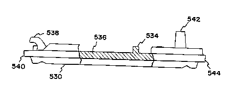
Referring in particularto-Figures 21, 26, 27
and 29, base plate 530, and base 532-are shown.
Extending from main surface 536 are a pair of hooks 538
adjacent to a first transverse end 540. A loop 542
extends from the main surface 536 adjacent to a second
transverse end 544. A plurality of tube guide pairs
545, 546, 547, 548 extend from main surface 536 and are
spaced apart to receive a flexible tube, in a general
direction parallel to first and second longitudinal
sides 541, 543 of main surface 536. In Figure 26,
background portions have been removed behind the cross-
sectional portion for clarity. In Figure 27, a tube-549
is shown in dashed lines.
Referring now to Figures 24 and 25, base plate
630, and base 632 are shown in greater detail.
Extending from main surface 636 are a pair of hooks 638
adjacent to a first transverse end 640. A loop 642
extends from main surface 636 adjacent to a second
transverse end 644. A plurality of tube guide pairs
645, 646, 647, 648 extend from main surface 636 and are
spaced apart to receive a flexible tube, in a general
direction parallel to first and second longitudinal
sides 641,- 643 of sedond cassette 666. In Figure 25, a
tube 649 is shown in dashed lines.
As shown by a comparison of Figures 24-and 25
with Figures 26 and 27, projection 534 is in a different
relative location to projection 634 in a direction
parallel to longitudinal sides 641, 643. It should also
WO 95/28190 2 18 T 7 6 9 PCT/1JS95/04527 0.
34
be noted that Figures 24 and 25 illustrate the integral-
constxuction between base plate 630 and base 632.
Cassette 626 also includes features for more accurate
centering of tube 649 which is larger than tube 549,
such-as the V-shaped passages provided in connection
with guide pairs 645, 646, 647, 648.
Also, cassette 626 includes clip features for
releasably gripping tube 649 to provide-a mechanical
hold down during adhesive attachment of tube 649 to
cassette 646. In particular, first clip 650 and second .
clip 652 provide hold downof tube 649 to cassette_.626.
First clip 650 and second clip 652 hold the tube in
place during assembly, allowing the adhesive-to set up
without the need for special clamps or external --
fixtures.
Referring now to Figure 28, third cassette 726
is shown. With respect to_Figure 28, a base plate 730
is illustrated. Base 532 shown in Figure 29 is useable
with base plate 730 shown in Figure 28. Projection 734
is in a different.relative location on base plate..730
than projection 534 of base plate 530 and projection 634
of base plate 630. Projection 734 can be_indicative of
a different cassette ptoperty to differentiate cassette
726 from cassettes 626, 526. For example, cassette 726
may include an indication that an air filter is present
to identify to the control module when the cassette is
utilized with a reservoir=including an in-line air -
filter.
WO 95128190 2187769 PCT/US95l04527
The cassette identification system of Figures
21-29 incorporates features of embodiments described in
various of Figures 1, lA, 2, 14, 15, 18, and 20, for
example. The system of Figures 21-29 may be
5 advantageous over mechanical switches, such as
microswitches, since little or no emphasis need be
placed on overtravel, individual adjustment, arcing
problems, and mechanical-wearing of the switch.
Inductive, magnetic, or reflective systems may require
10 the placement of an additional element on the cassette
during manufacture. A projection as in Figures 21-29
can be integrally formed on-the cassette during
manufacture, possibly simplifying manufacture. Force
sensitive resistors may be prone-to problems due to
15 typical range of necessary movement and the typical
tolerances of the disposable cassettes. Also, the
plastics associated with the FSR or its spring may be
subject to creep problems over time, possibly further
complicating the range of motion and tolerance problem.
20 Make or break switches where the contacts aremounted to
a moveable plunger, for example, may be prone to failure
due to the failure of the contact points, such as due to
pitting or corrosion, or due to the components getting
stuck open or closed.
25 Reciprocally mounted plungers and slotted
optical sensors are useful to solve some ofthe above-
possible problems and other problems with cassette
identification systems. However, it is to appreciated
WO 95/25190 - - PCT/US95/04527 .
2187769
36
that insome instances the-use of microswitches, FSR's,
inductive switches, magnetic switches, reflective .
elements, moving contacts,. or other systems noted above
may be desireable.
While the present invention has been described
in connection with the preferred embodiments thereof, it
will be understood-many modifications will be readily
apparent-to_those skilled,_in the art, and this
application-is intended to-cover any adaptations or -
variations thereof_ It is_intended this invention be
limited only by the claims and equivalents thereof.