Note : Les descriptions sont présentées dans la langue officielle dans laquelle elles ont été soumises.
. .. ' 218~lo2
-
PATENT
ATTORNEY DOCIOE:T NO: 0 7 0 91/ 0 0 2 0 01
PIPE REHABILITATION SYSTEM AND METHODS
Backqround of the Invention
Underground service pipes such as sewers which make
up the utility infrastructure need replacement or
rehabilitation as they age. Through normal service the
lines, typically made of concrete, deteriorate or break
allowing waste to escape. The buried pipes present access
problems. Also, it is desirable to maintain sewer service
while the replacement or rehabilitation of the sewer line
takes place.
Repairing a service line can involve digging up most
or all of the line and replacing the pipe. This is costly,
labor intensive and disrupts normal service. Alternative
methods such as pipe bursting have been developed which
includes breaking up the old pipe underground and following
the bursting operation with placement of new pipe in the
space provided. Another alternative method involved
extracting the old pipe at intervals and replacing it with
new pipe by forcing the new pipe into the space provided
after the extraction process. The old pipe that was
extracted needed to be disposed of adding another economic
factor to the method. Some of these methods utilized pipe
jacking machines with hydraulic rams or mechanical drivers
to push the new pipe in place. In some cases the pipe
jacking equipment took up space in the excavation next to
the pipe to be burst or extracted. The access thorough
existing manholes was insufficie~t to accommodate the pipe
jacking equipment.
~ ' 2188~02
The renewal or rehabilitation of the service lines
without digging up the line was developed by inserting new
pipe or slip lining with materials such as plastic pipe
liners inside the old pipe. Rehabilitation of old pipe with
a new internal slip lining requires cleaning the existing
host pipe of debris that has built up with use. Some
methods utilize stationary derricks for the cleaning
operations with a drag bucket. The derricks need to be
reset after each operation. The bucket size may be limited
by the height of the derrick used to hoist the bucket to the
surface. The pipe liner is pushed into the host pipe.
Often the pressure exerted in the pushing operation is not
evenly distributed causing damage to the liners.
The host pipe should be tested after the cleaning
process to determine if debris has been removed and the pipe
liner can fit. The new joints of liner pipe is then placed
in the host pipe. The liner generally has a slightly
smaller diameter than the inside of the host pipe.
Summary of the Invention
This invention is a system for rehabilitating pipe
such as sewer lines which renews the existing service lines
without disrupting the flow through the lines. In this
description the pipe may be described as a sewer line that
is in need of rehabilitation. The system retains the host
pipe and therefore the value of the structure in place while
not creating additional waste disposal concerns with the
extracted pipe. The system utilizes mobile equipment such
as conventional excavators that are fitted with winches on
the attachment points for custom tools, the winch
manipulates and lifts the buckets for the cleaning
operation, and the test mandrel and the pipe liner in the
slip lining renewal operation.
-- 2
CA 02188102 1998-09-22
The system for cleaning the sewer line is often needed
prior to the slip lining process because of the debris built up
in the sewer line after years of use or rapid deposition of
debris because of adverse environment conditions. The present
invention utilizes equipment that can be used for both the
cleaning and relining process as well as testing the host pipe
prior to relining to confirm that the interior of the host pipe
is clear and the liner pipe will be received without damage.
The invention provides a system for use in rehabilit-
ating pipe comprising a down hole boom with a first winchaffixed thereto that is inserted in first access area which is
a shaft to a host pipe; a guide roller adjustably mounted along
the down hole boom; a first cable spooled on the first winch
that can be driven into the access shaft over the guide roller
which is fixed in position to guide the cable into the host
pipe; a host vehicle with a boom on the surface adjacent to a
second access area to the host pipe a selected length from the
first access shaft; a second winch on the end of the boom of
the host vehicle, capable of movement from the surface to the
host pipe through a second access; a second cable spooled on the
second winch that can be positioned by the boom and driven into
the host pipe; a housing mounted to the end of the boom and
surrounding the second winch that allows for free movement of
the second cable into the host pipe; and the cables on the first
and second winch capable of disengagable attachment to equipment
used to rehabilitate host pipe.
In the rehabilitating system of the invention the
length of host pipe is accessed on both ends. Manholes already
77252-11
CA 02188102 1998-09-22
present can be used as access on at least one end of the host
pipe and are generally large enough for one end of the operation.
A larger excavation to accept the new pipe liner and a test
mandrel is required on the other end of the host pipe from the
manhole.
In an embodiment of the system the host pipe is
accessed through a shaft that can be an existing manhole. The
down hole boom is inserted into the shaft. The guide roller is
adjustably mounted so that when the down hole boom is placed in
the shaft the guide roller is positioned to guide the cable
from the winch over the roller into the host pipe. The down
hole boom generally extends above the surface of the shaft.
The winch is preferably mounted on the part of the boom above
the surface. In one embodiment the winch on the down hole boom
is also mounted to a mobile vehicle such as an excavator.
A selected length from the access shaft another
access area to the host pipe is provided that is large enough
to accommodate other equipment necessary for the rehabilitation
process such as lengths of the new pipe liner. The host vehicle
with a movable boom such as an excavator is positioned at the
surface of the second access area. Various embodiments of the
system use conventional excavators which are easily transported
from site to site. A second winch is mounted on the end of the
boom. The boom operator can manipulate the boom and winch so
that the winch can be moved from above the surface into the
access area and to the mouth of the host pipe. In the preferred
embodiment, a housing is mounted to the end of the boom and
surrounds the winch. The housing protects the winch, but allows
77252-11
CA 02188102 1998-09-22
for free movement of the cable spooled on the winch. The winch
housing is attached to the boom on the custom attachment points
used for other types of tools. The cables from both winches
are capable of disengagable attachment to equipment used to
rehabilitate the host pipe.
One of the pieces of equipment used to rehabilitate
the host pipe which is part of the system is a cleaning bucket.
The semicircular cleaning bucket is sized to be received in the
host pipe. The cleaning bucket has a leading edge with a flap
door that is generally semicircular and hinged to the top of
one end of the bucket. The flap door swings to the inside of
the bucket from the closed to open position. An open end is
opposite to the flap door on the cleaning bucket. The cleaning
bucket has points of attachment to the cables such as yokes.
An additional piece of equipment of the system is a
test mandrel used to determine if there are any obstructions in
the host pipe prior to lining. The test mandrel is a
cylindrical member with beveled edges on both ends. A plurality
of internal ribs and internal pulling yokes are disposed inside
the cylindrical member.
The invention also provides a pulling mandrel for use
in lining pipe comprising a circular member sized with a
diameter to be received inside the host pipe and contact the
circumference of a liner for the host pipe which liner has been
placed at the mouth of the host pipe in an access area; a
plurality of spokes extending from the circular member and
converging to middle of the circular member to a central hub
77252-11
CA 02188102 1998-09-22
allowing flow therethrough; the hub having an opening of
sufficient diameter to accompany a cable passing therethrough
from a winch; and a securing means for attaching the cable from
the winch to the hub of the circular member whereby upon
spooling the winch the outer circumference of the pulling
mandrel engages the pipe liner.
The pulling mandrel is designed to distribute the
pulling forces in an even manner around the pipe liner while
it is pulled by the cable on a winch and pulled inside the host
pipe. The mandrel also provides for areas of flow therethrough
so the sewer remains in service during the slip lining operation.
From another aspect, the invention provides a method
for using a system for lining pipe comprising the steps of (a)
selecting a length of host pipe for lining; (b) accessing the
host pipe on both ends of a selected length of the host pipe
for lining; (c) positioning a down hole boom vertically in a
shaft that accesses one end of the host pipe that has a first
winch and a guide roller mounted thereon whereby the first winch
drives a first cable down the shaft into the host pipe over the
guide roller that positions the first cable into the host pipe;
(d) mounting a second winch with a second cable on a movable
mount positioned at an access area at the host pipe opposite
to the end where the down hole boom is located sufficient to
accommodate a length of pipe liner and the second winch capable
of movement from the surface to the host pipe; (e) passing the
first cable from the first winch mounted on the down hole boom
over the guide roller through the length of the host pipe; (f)
further passing the cable through a length of liner pipe sized
- 5a -
77252-11
CA 02188102 1998-09-22
to line the inside of the host pipe which has been lowered into
the access area next to the mouth of the host pipe using the
second winch on the movable mount; (g) further threading the
first cable through a circular pulling mandrel with a central
opening in a hub that has spokes extending therefrom to a
circular outer ring; (h) securing the first cable to the pulling
mandrel so that upon spooling the first winch the pulling
mandrel contacts the circular end surface of the pipe liner;
(i) pulling the pipe liner and pulling mandrel with the first
cable and first winch through a length of the host pipe
approximately the length of the pipe liner; (j) releasing the
first cable from the pulling mandrel and removing the pulling
mandrel; (k) lowering a second length of pipe liner into the
access area adjacent to the first length of pipe liner with the
second winch and a second cable; (1) placing the pulling
mandrel adjacent to the second length of pipe liner; (m) secur-
ing the first cable to the pulling mandrel so that upon spooling
the first winch the pulling mandrel contacts the circular end
surface of the second length of pipe liner; (n) pulling the pipe
liner and pulling mandrel with first cable and first winch
through a length of the host pipe approximately the length of
the second pipe liner length; and (o) repeating steps (k)
through (n) until the length of host pipe is lined.
The cleaning method starts with the selected length
of host pipe described above that has at least two access
points with one access that can be a manhole. The cleaning
bucket described above is attached to a cable. In an embodi-
ment one cable is strung between the two winches with the
- 5b -
77252-11
CA 02188102 1998-09-22
cleaning bucket attached. In a preferred embodiment of the
system the cable from the winch on the down hole boom attached
to a yoke on the leading edge of the cleaning bucket and the
cable on the movable boom is attached to the open end of the
cleaning bucket.
The cleaning bucket is lowered into the access area
serviced by the winch on the movable mount. The cleaning
bucket is pulled by spooling the winch on the down hole boom
through the host pipe with the leading edge first so that the
flap door is open. The drag is reversed by spooling the winch
on the movable mount so that when the cleaning bucket is pulled
in the opposite direction the flap door closes and traps
debris. The cleaning bucket with the debris is hoisted to the
surface by spooling the winch on the movable mount and raising
the mount. The debris is discharged from the bucket. The
processses are repeated until the host pipe is cleaned.
- 5c -
77252-11
~ ~188~02
.
Generally the next method used in sewer
rehabilitation that utilizes the system is a testing
procedure to determine that the pipe liner will fit suitably
in the host pipe. This operation involves pulling a test
mandrel which is a tubular member with the approximate
diameter and length of the pipe liner through the host pipe.
In the preferred system, the test mandrel has beveled edges
on each end and performs a final sweep of the host pipe
loosening and removing any remaining solids or mineral
deposition on the inside of the host pipe. Also, the
internal ribbing provide weirs for collection of the debris.
The method for using the system for testing includes
lowering the test mandrel in the access area next to the
host pipe. The cables from both winches are attached to the
lS internal yokes inside the test mandrel. The winch on the
down hole boom is spooled so that the mandrel travels
through the host pipe toward the access shaft. The travel is
then reversed by spooling the winch on the movable mount.
The ease of travel by the mandrel through the host pipe is
indicative of an obstruction or lack thereof.
The host pipe is lined after the cleaning and
testing process. However lining might be necessary if there
has been some structural damage to the integrity of the
sewer pipe and a cleaning process is not necessary. At one
access area the excavation is large enough to accommodate a
length of pipe liner. The same system is used in the
cleaning and testing operation may be used in relining the
host pipe. A cable on the winch on the down hole boom is
passed through the length of the host pipe. The cable is
then passed through a length of pipe liner and the pulling
mandrel that is placed adjacent to the pipe liner that has
also been lowered into the access area.
2188102
The cable is secured to the pulling mandrel so that
when the cable on the down hole boom is spooled it pulls the
pipe liner into the host pipe. The cable is spooled
approximately the length of the pipe liner section. The end
of the cable is released from the pulling mandrel. Another
section of pipe liner is placed in the access area at
trailing end of the first pipe liner section and the pulling
mandrel is placed at the end of the second pipe liner
section. The cable is spooled and the next section of the
pipe liner is pulled into the host pipe. This process is
repeated until the host pipe length is lined.
Another method of the invention is a method for
rehabilitating a host pipe that is adaptable to smaller pipe
and can be performed while the sewer is in service. The
alternate method is suitable for remote or difficult to
access areas. This alternate method uses basically the same
equipment for all the rehabilitation work to clean and line
the pipe. The alternate method involves selecting the host
pipe and accessing two ends through shafts that can be
existing manholes. An excavation intermediate to the two
shafts is dug and a portion of the host pipe is removed.
Two down hole booms are inserted into the access shafts
and extend above the surface. Winches are positioned
adjacent to the down hole booms. The cable spooled on the
winches are placed over guide rollers on the down hole booms
so that the winches can pull the cable down the access shaft
into the host pipe to the intermediate access area. The
alternative method includes down hole booms and winches that
can be skid mounted or mobile mounted.
A hoist device with at least one cable is placed at
the surface of the intermediate access area to the host
pipe. A cleaning bucket as described above is lowered into
the intermediate access area by the hoist and attached to
-- 7
2t88102
one of the cables associated with the winch and down hole
boom. Cables from the winches on the down hole booms are
attached to either end of the cleaning bucket. As the
cleaning bucket is pulled through the host pipe and reversed
the debris is trapped. The cable on the hoist is attached
to the cleaning bucket. The cleaning bucket is withdrawn
from the intermediate access area and the collected debris
is discharged at the surface. With two access shafts to the
host pipe, the cleaning bucket can used on both sections of
the host pipe extending from the intermediate access area.
The testing method utilizes the same equipment. A
test mandrel is lowered into the intermediate access area by
the hoist. Cables from the two winches are attached to
either end of the test mandrel and it is pulled through the
host pipe to determine if any obstruction exists.
The same equipment is used to line the host pipe.
The hoist introduces pipe liner into the intermediate
excavation area. Both sections of host pipe that extend
from the intermediate access arèa are lined. A cable
extended from one of the winches into the intermediate
access area is passed through a section of pipe liner and
then secured to a pulling mandrel. The cable is spooled
approximately the length of the pipe liner. The pulling
mandrel is removed and another section of pipe liner is
introduced into the intermediate access area by the hoist
and aligned to abut with the first section pulled into the
host pipe. The cable is released by the winch and pulled
through the second section of pipe liner and secured to the
pulling mandrel. The winch spools the cable pulling the
first and second sections of pipe liner into the host pipe.
The process is repeated using both winches until the host
pipe extending from the intermediate area is lined.
218~3102
Brief Description of the Drawin~s
Fig. 1 is a schematic depiction of the sewer
rehabilitation system during the cleaning process.
Fig. 2 is a schematic depiction of the sewer
rehabilitation system during the testing process.
Fig. 3 is a schematic depiction of the sewer
rehabilitation system during the host pipe lining process.
Fig. 4 is a schematic depiction of an alternative
embodiment of the sewer rehabilitation system showing the
cleaning process of the sewer line.
Fig. 5 is a alternative embodiment of a sewer
rehabilitation system showing the testing of the sewer line.
Fig. 6 is a schematic depiction of an alternate
system showing the host-pipe lining operation.
Fig. 7 is a perspective view of a cleaning bucket.
Fig. 8 is an end view of the cleaning bucket with
the f lap door closed.
Fig. 9 is a side view of the cleaning bucket showing
the swing of the f lap door.
Figs. lOa, lOb and lOc are perspective views of the
cleaning bucket and winch during the discharge process.
Fig. 11 is a perspective view of the pulling
mandrel.
Fig. 12 is a perspective view of the pulling mandrel
and direction of pipe liner.
Fig. 13 is an exploded view of the pulling mandrel
with the locking teacup, cable and pipe liner.
Fig. 14 is a side view of the exploded depiction of
the locking teacup, pulling mandrel, pipe liner and cable.
Fig. 15 is a partially perspective view of the test
mandrel that also shows the internal ribs and yokes by the
dotted lines.
Fig. 16 is a cross-section at line 16 of Fig. 15.
g
2~88iO2
Fig. 17 is a perspective view of the winch and
housing.
Fig. 18 is a side view of the winch and housing.
Fig. 19 is a down hole boom with two adjustable
guide rollers for use in an alternative embodiment of this
system.
Fig. 20 is an alternative embodiment of a down hole
boom with two adjustable guide rollers for use in an
alternative embodiment of this system.
Fig. 21 is a perspective view of a down hole boom
and winch associated with a movable mount.
Detailed Description of the Invention
A system for rehabilitating sewer lines is shown in
Fig. 1 during cleaning of a host pipe. As shown in Fig. 1,
the host pipe 10 has been accessed at one end of the
selected length for rehabilitation by access shaft 12 which
can be an existing manhole or other existing access shaft to
the sewer line which is wide enough to accommodate down hole
boom 14. Down hole boom 14, as shown in Fig. 1, extends
from above the surface of the manhole entrance to the bottom
of the manhole and rests on the bottom of the manhole. In
the preferred embodiment down hole boom has a guide roller
16 at the end of the down hole boom close to the mouth of
the host pipe. The guide roller is adjustable along the
length of the boom so that cable 18 from winch 20 can extend
into the access shaft along the down hole boom around guide
roller 16 and into the host pipe. Depending on the diameter
of the host pipe, guide roller 16 can be adjusted on the
down hole roller so that the cable 18 extends preferably to
the host pipe. Auxiliary guide roller 13 mounted on the
down hole boom 14 is also shown. The extension of the down
hole boom may be adjusted by attaching different lengths
- 10
2t 8~t ~2
together. A joinder point 15 is shown on the down hole boom
14 where two lengths are fastened together. Winch 20 is
mounted on the part of the down hole boom extending above
the manhole. However the winch could be located beneath the
5 surface in the manhole. Winch 20 is also mounted to a host
vehicle 22 which in Fig. 1 is shown as a conventional
excavator. However, down hole boom 14 and winch 20 may be
supported at the surface above access shaft 12 by a
stationary support. Fig. 1 illustrates the use of a host
vehicle 22 to illustrate the transportability of the system.
The winch 20 spools and pulls cable 18. The winch
may be mechanically driven, but in the preferred system the
winch mechanism is hydraulically driven and operated. Cable
18, threaded on winch 20, extends the length of down hole
boom 14 may be guided on the down hole boom by additional
guide rollers, such as auxiliary guide roller 13 then around
guide roller 16 at the mouth of host pipe 10 and into the
host pipe. In Fig. 1 the cleaning bucket 26 is attached to
cable 18 at yoke 28.
A second access area generally indicated by
reference numeral 30 is excavated a selected length from
access shaft 12. The second access area extends from the
ground surface and a portion of host pipe 10 is removed. As
shown in Fig. 1 a system of this invention can be used
25 while the sewer is flowing and the host pipe was removed
down to the spring line to contain the sewer effluent.
Adjacent to the second access area is host vehicle 32 which
is equipped with a movable boom mechanism. Host vehicle 32
is a movable mount and can be a conventional excavator. On
30 the end of the boom a second winch 36 is attached to point
of attachment for a backhoe. The winch 36 is surrounded by
housing 38 that allows for free movement of cable 40 into
the access area host pipe. In Fig. 1 cable 40 is shown
- 11 -
2t~tO2
attached to yoke 42 on cleaning bucket 26. Both cables 18
and 4 0 are used to engage various pieces of equipment during
the rehabilitation of the host pipe.
As shown in Fig. 1 the host vehicle 32 stabilizes
the boom and the winch 36 so that there is freedom of
movement from the mouth of the host pipe to above ground.
Boom 34 in association with winch 36 can introduce and
withdraw equipment used in the rehabilitation process in and
out of the second access area.
Fig. 1 is a schematic drawing showing the cleaning
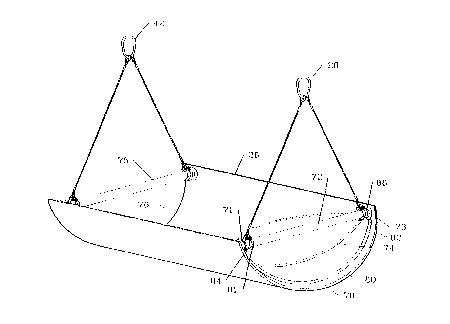
process. Cleaning bucket 26 is shown in more detail in
Figs. 7, 8 and 9. Referring to Fig. 7 cleaning bucket 26 is
generally semi-circular with a diameter size to be received
into the host pipe. The cleaning bucket 26 has a leading
15 edge 70 with a flap door 74 hinged to the top end of one end
of the bucket on a rotating hinge rod 72 that allows the
flap door to swing inside the bucket from a closed to open
position. A built up door stop 80 in the form of a
semicircular edge extending from leading edge 70 provides a
20 means for closing flap door 74. Any other closure means can
be used. The hinge rod 72 is secured in bushings 71 and 73
that allow for swing of the hinge rod. Other retaining
means that allow the hinge rod to swing are also suitable.
The bucket is open at end 76 opposite to the flap door 74.
25 Yokes 28 and 42 as shown in Fig. 1 are also shown in Fig. 7
as attachment means to engage the cables. Yoke rod 75
across the top of the bucket is provided at open end 76.
Fig. 8 is an end view of the cleaning bucket 26 with the
flap door 74 in the closed position. In Fig. 8 yoke pins 81
30 and 82 are shown which are provided on hinge 72 to hold yoke
rings 84 and 86 (shown on Fig. 7) in place. Similar yoke
rings and pins may be provided on yoke rode 75. Any means
218~102
for holding yoke rings in place can be utilized. Fig. 9
shows the flap door 74 movement on hinge rod 72.
In Fig. 1 the cleaning bucket is being drug through
the host pipe and the yokes 28 and 42 are pulled outwardly
from either end of the cleaning bucket. In the cleaning
process the cleaning bucket 26 is lowered into the second
access area by boom 34 and winch 38. The cable 18 is
attached to yoke 28 and cable 40 is attached to yoke 42.
Winch 20 spools cable 18. Cleaning bucket 26 travels
through the debris in host pipe 10 with the leading edge 70
being dragged first and flap door 74 pivots to the inside of
the cleaning bucket. Fig. 9 shows the swing of flap door 74
that occurs during the spooling of cable 18. The drag on
the cleaning bucket is reversed by spooling cable 40 on
winch 36. Flap door 74 closes as it collects debris and the
cleaning bucket is withdrawn to the surface. As the
cleaning bucket is drawn to the surface, cable 18 is
slackened to allow for withdrawal of the cleaning bucket
without need to detach cable 18.
In Fig. 1 there is a schematic depiction of
discharging debris the cleaning bucket into collection bin
44 at the surface near the access area. Figs. lOa, lOb, and
lOc are details of the discharge operation of the cleaning
bucket. In the current embodiment fixed cable 102 is
attached to the winch housing 38. Cable 102 is a fixed
chain that is not attached to the winch or any other
spooling mechanism. The chain is attached to yoke 28 by
personnel on the site. Cable 40 is spooled to hold the
cleaning bucket 26 in a relatively horizontal position so
30 that the debris does not spill out the open end. The boom
operator positions boom 34 with the winch and the cleaning
bucket over collection bin 44 and spools out cable 40
allowing the bucket to tip and discharge the debris as shown
- 13 -
2'188tO2
in the details of Figs. lOb and lOc. The fixed cable 102
holds the end of the cleaning bucket with the flap door in a
relatively stationary position. When the leading edge 70 of
the bucket is reversed for instance when the cleaning
operation is in the opposite direction, the fixed chain 102
can be positioned on the other side of the winch housing.
After the discharge from the cleaning bucket it is
reintroduced in the access area by boom 34 and into the
mouth of the host pipe. The cable 18 is spooled up and the
process is repeated until the debris is cleared from the
host pipe.
Fig. 17 is a detailed perspective view of the
housing 38 surrounding winch 36. The fixed cable 102 used
to hold the cleaning bucket during discharge is also shown.
Lines 120a and 120b supply hydraulic fluid to the winch are
also shown. The winch housing surrounding the cable has an
open bottom to allow for free movement of cable 40. In the
preferred embodiment the winch housing is built of strong
metal such as heavy steel that can bear the weight of an
excavator. The bottom of the winch housing is relatively
flat. The winch housing is constructed with attachment
plates 121 and 123. The attachment plates are provided with
attachment points which are shown as attachment pins at
reference numerals 122 and 124 for plate 123 to the stick 35
of boom. The winch housing attachment pins are spaced to
correspond to custom tool attachments designed for
conventional excavators so that in the preferred embodiment
the winch can be used on an excavator just as other custom
attachments are used. Fig. 18 is a side view of winch
housing 38 and the attachment to the stick portion 35 of the
boom where the other custom attachments or tools are
typically attached.
218~1~2
Fig. 21 is a detail of an embodiment with the down
hole boom 14 shown attached to winch housing 21. The winch
housing is constructed in the same fashion so that it
attaches to end of a boom of an excavator where a bucket or
other tool is generally attached. The down hole boom is
configured with back to back C shaped beams spaced apart
with guide rollers positioned in between the C-beams. Fig.
21 shows a down hole boom with guide roller 16 and auxiliary
guide roller 13. Both guide rollers are adjustable by using
pins inserted into openings along the down hole boom. In
the case of guide roller 16, pin 17 is inserted through
openings in C-beams and held in place by a pin retainer such
as a clip, bolt and washer or other means known to those in
the art. The down hole boom has numerous pins that are
positioned in slots along the length of the down hole boom
so that the guide rollers can be positioned as needed. As
shown in Fig. 21, guide roller 16 has been positioned so
that the cable is positioned to be received in the host pipe
(not shown). To facilitate smooth driving of the cable
additional guide rollers such as auxiliary guide roller 13
can be included along the length of the down hole boom 14.
As shown in Fig. 21 the cable can be fed on either side of
guide roller 16 depending on which direction cable is driven
into the host pipe.
Fig. 2 is a schematic of the system figured for
testing the host pipe with test mandrel 46 to determine if
there is any additional debris or obstruction in the host
pipe prior to lining. The same equipment is used including
the down hole boom 14 with associated guide roller 16 and
winch 20 which spools out and pulls cable 18. The second
host vehicle 32 and associated boom 34 with winch 36
surrounded by housing 38 and cable 40 are used in the
testing process. Winch 20 is shown in housing 21 and
- 15 -
218~102
mounted to the boom of host vehicle 22. The host vehicle
has travelled to the other side of the access shaft. The
down hole boom 14 is shown braced against the bottom of the
host pipe.
Test mandrel 46 is lowered into the access area by
the boom on host vehicle 32. The test mandrel is a
cylindrical member sized approximately the same diameter as
the pipe liner. The test mandrel should be of sufficient
length to test joint deflection in the host pipe to avoid
damage to the new liner. Cables 40 and 18 are attached to
the test mandrel 46 so that upon spooling the appropriate
cable the mandrel may travel through the host pipe if it is
clean and free of obstruction. As shown in Fig. 2, winch 20
will spool cable 18 so that the test mandrel travels to the
end of the host pipe 10 at the shaft or manhole 12. Then
winch 36 will spool cable 40 and pull the test mandrel back
to the access area. Winch 36 is positioned so that the
cable 40 can be driven into the central part of the mouth of
the host pipe as shown in Fig. 2.
Detailed drawings of the test mandrel of the system
are shown in Figs. 15 and 16. Test mandrel 46 is a
generally cylindrical member and has circular bevelled edges
48 and 50. Fig. 16 is a cross-section of test mandrel 46.
Fig. 15 shows the internal component of the test mandrel,
including ribs 52a, 52b and 52c. The ribs provide
reinforcement for the test mandrel. Also, beveled edges 48
and 50 provide a final sweeping of the cleaned host pipe and
assist in loosening residual deposits such as mineral
deposits and other deposited debris. The ribs 52a, 52b and
52c act as weirs to collect the residual deposits inside the
test mandrel in addition to providing structural support.
The test mandrel of this invention also has internal yokes
54a and 54b. Yoke 54a is attached to rib 52a at slots 49
- 16 -
. 21~8tO2
..
and 51. Yoke 54b is similarly situated on the other end of
the test mandrel. The yokes can be made of any type of
material and is shown as two cables attached to the rib with
a central joinder for the cable attachment, however any
other type of yoke attachment to the test mandrel could be
used. The test mandrel has lifting means one of which is
illustrated in Figs. 15 and 16 as lift pin 47 which is fixed
inside the test mandrel under a slot. The lift pin 47
provides an attachment means for a cable to lift the test
mandrel. Other lift pins may be provided as shown in Fig.
15.
Fig. 3 illustrates the lining process using the
system of the present invention. The same equipment as
shown in Figs. 1 and 2 is used to place the liner pipe in
position, and in addition a pulling mandrel 56 is employed.
As shown in Fig. 3, cable 18 is positioned in the central
area of host pipe 10 by guide roller 16 is threaded through
the host pipe to the second access area. Pipe liner
sections 58, 59, 60 and 61 are shown in Fig. 3 during a
20 lining process. The process in initiated by passing cable
18 through a first section of pipe liner (as shown in Fig. 3
pipe liner section 61) and secured to pulling mandrel 56.
This process occurs in the excavated access area 30. Winch
20 pulls cable 18 approximately the length of the section of
25 pipe liner so that the pipe liner is drawn into host pipe
10. As shown in Fig. 3 section 61 was the first section of
pipe liner drawn into the host pipe. Pulling mandrel 56 is
unfastened from the cable and a second section of pipe liner
(pipe liner section 60 as shown in Fig. 3) is lowered into
the second access area by the boom on host vehicle 32 and
winch 36. The second section of pipe liner 60 is abutted to
the first section of pipe liner 61 and cable 18 is pulled
therethrough and secured to test mandrel 56. Winch 20
- 17 -
218~to2
spools cable 18 pulling the first and second lengths of pipe
liner so that section 60 is pulled into the host pipe and
section 61 travels further into the host pipe. The process
is repeated until the section of host pipe is lined.
As shown in Fig. 3 the lining process can be carried
on simultaneously while another section of liner pipe 58 is
positioned into the access area. Also in Fig. 3 the host
vehicle 32 is shown with an operator using a remote control
to manipulate the winch and boom while the lowering the pipe
liner into the access area 30.
The system of this invention uses a pulling mandrel
shown in more detail in Fig. 11. The pulling mandrel 56 has
a circular member 62 with the flange 65 which is sized to be
received in the host pipe and flange 65 contacts the
circumference of the pipe liner. A plurality of spokes
converge to a central hub 66. The spokes are designated
with reference numerals 64a through 64h. Hub 66 has a
circular opening which is sized to accompany a cable passing
therethrough. The pulling mandrel allows for flow through
the spokes. Also, the pulling mandrel distributes the
pulling load evenly on the pipe liner. In Fig. 11 a hook 67
is shown which is used for attachment to a cable for
lowering the test mandrel into the access areas when
necessary. Fig. 12 shows the pulling mandrel 56 contacting
a section of pipe liner 63 and illustrates the detail of the
cable 61 passing through hub 66. The end of the cable 61 is
secured with attachment 68 known as a teacup. Any
attachment that securely fastens the cable to the hub of the
pulling mandrel may be used. Figs. 13 and 14 are exploded
views showing the teacup 68, pulling mandrel 56 and section
of pipe liner 63 and cable 61.
Fig. 4 is an alternative method for slip lining a
host pipe that can also be performed while a sewer is in
- 18 -
~ 218~102
.
service. The alternate method can be used for remote or
difficult to access areas. The alternate method uses some
of the same components illustrated in the system previously
described. The host pipe 200 to be cleaned is selected and
access areas that will be used for the rehabilitation
process are also selected. As shown in Fig. 4 two access
areas at either end of the host pipe 200 are access shafts
202 and 204 which can be existing manholes. The manholes
can be located in confined areas such as residential
property. Down hole booms 206 and 208 are positioned
vertically in the access shafts 202 and 204 respectively.
Each of the down hole booms shown in Fig. 4 has at least one
guide roller positioned on the end of the boom that extends
above the access shaft. In the preferred embodiment, guide
rollers are adjustable along the length of the down hole
boom so that guide rollers can be moved on the down hole
boom to posltion a cable in the access shaft and into the
host pipe. In Fig. 4 guide rollers 210 and 212 are shown
positioned on down hole booms 206 and 208 respectively.
Fig. 4 shows different types of winch placements.
In access shaft 202 the winch 214 is mounted on down hole
boom 206 and also mounted to a mobile vehicle 216. Cable
218 extends from winch 214 along down hole boom 206 into
host pipe 200. Cable 218 passes around guide roller 210 so
that it is aligned to enter the host pipe. In Fig. 4 the
winch 214 is mounted on the mobile vehicle and winch 214 can
serve as a positioning means to guide the cable 218 along
the down hole boom 206. Another guide roller 211 which is
optional is also shown on down hole boom 206.
Also shown in Fig. 4 is skid mounted winch 220. A
platform or skid 222 is set up at the access shaft 204 and
the winch is secured and mounted to the platform 222. When
using a skid mounted winch it is preferred that the down
-- 19
- 218810~
hole boom have guide roller 224 on down hole boom 208 to
guide cable 226 from winch 220 on down hole boom 208. As
shown in Fig. 4, cable 226 passes around guide roller 212 to
align cable 226 to enter the host pipe 200.
An excavation 228 provides an intermedlate access
area 228 to the host pipe 200. As shown in Fig. 4, a
portion of the host pipe 200 is removed to approximately the
spring line 230. Hoist 232, which may be a conventional
crane, is positioned adjacent to the intermediate access
area 228. The hoist has at least one cable that can be
lowered into the access area. In the preferred embodiment
the hoist has two cables 234 and 236 that are operated in
conjunction with crane 238.
In the cleaning operation shown in Fig. 4, a
cleaning bucket 240 is used essentially in the same manner
as described and illustrated previously in Figs. 1, 7, 8, 9,
lOa, lOb and lOc. Cables 218 and 230 are attached to yokes
242 and 244. The cables are spooled and released by the
respective winches 214 and 220 so that the bucket collects
debris from both sections of the pipe extending from the
intermediate access area to access shafts 202-and 204. In
the alternate method, cleaning bucket 240 with trapped
debris is pulled to the intermediate access area 228. Hoist
cables 234 and 236 are attached to yokes 242 and 244 on the
cleaning bucket. The hoist raises the cleaning bucket
withdrawing it from the host pipe to the surface at the
intermediate access area and further raises and tips the
cleaning bucket by manipulating cables 234 and 236 to
discharge the accumulated debris into collection bin 246.
It is not necessary to unfasten cables 218 and 226 because
the cable winches can be released out to provide enough
slack. The cleaning bucket 240 is lowered into the
intermediate access area 228 by hoist 232. The cleaning
- 20 -
21~102
bucket is then drug through the debris filled host pipe in
the same manner of operation as previously described to
complete the cleaning of one section of the host pipe
between the intermediate access area and one of the access
5 shafts. To clean both sections of the pipe extending from
the intermediate access area, it is necessary to reverse the
leading edge of cleaning bucket 240 to provide for debris
entrapment as previously discussed.
Fig. 5 illustrates an alterative method for testing
a host pipe. The access area arrangement is similar to that
in Fig. 4 which accesses host pipe 200. A skid mounted
winch 250 is placed adjacent to access shaft 252 with down
hole boom 254. The down hole boom skid mounted winch
arrangement is previously discussed in describing Fig. 4.
15 Access shaft 256 is serviced by winch 258 ~hat is mounted on
the bed of truck 260. Down hole boom 262 has guide rollers
264 and 266. The cable 268 from winch 258 goes around the
top of guide roller 264 which is placed near the top of down
hole boom 262. Guide roller 264 serves as a guide for the
20 cable 268 to travel along down hole boom 254 into access
shaft 256. Then cable 268 goes around guide roller 266 into
host pipe 200. In the preferred method, guide rollers 264
and 266 are adjustably mounted along the length of the down
hole boom so that they may be positioned as needed to guide
25 the cable smoothly from the winch and into the host pipe.
Similar guide rollers 270 and 272 are shown on the down hole
boom associated with the skid mounted winch.
Fig. 5 shows the test mandrel 274 in host pipe 200
during the testing process. The test mandrel 274 iS lowered
into the intermediate access area 276 by hoist 232. The
test mandrel 274 has been described in these discussions of
the invention. Cable 278 from the skid mounted winch is
attached to test mandrel 274 at the point of attachment on
- 21 -
2t88102
one end of the test mandrel while the test mandrel 274 is in
the intermediate access area. Cable 278 is attached to the
opposite end of test mandrel 274 while the test mandrel is
in the intermediate access area. The test mandrel 274 is
sized to fit inside the host pipe and pulled through the
host pipe to be tested for obstructions. In addition, the
test mandrel used can be described previously in Figs. 15
and 16 also provides an additional final sweep to collect
mineralized deposits or residual debris. The test mandrel
74 is pulled through the test pipe by alternatively spooling
the skid mounted winch 250 and the truck mounted winch 258
through the host pipe 200. The test procedure is completed.
The test mandrel is removed from host pipe 200 using hoist
232.
Fig. 6 illustrates the slip lining process of the
alternative method. In Fig. 6 the host pipe 200 is accessed
at intermediate access area 276. The skid mounted winch 250
is placed in the same position as shown in Fig. 5. Down
hole boom 254 is placed in access area 252. Skid mounted
winch 255 drives cable 278 into the host pipe using down
hole boom 254 and guide rollers 270 and 272 assisting in
positioning cable 278. In access area 256 the winch mounted
on the truck bed has been replaced by a winch 280 mounted to
a down hole boom 282 and also mounted to the stick of boom
284 of excavator 286.
As can be seen from Figs. 4, 5 and 6, the down hole
boom mounts into the access shafts can utilize any type of
mounting vehicle or skid placement which will secure a down
hole boom vertically in an access shaft. Winch 280 serves
as a guide for cable 288 along the down hole boom. Although
guide roller 290 is shown, it is optional as previously
described. Guide roller 292 at the bottom of down hole boom
282 aligns the cable into host pipe 200. As previously
- 22 -
2 1 88 1 02
.
discussed, the guide rollers are adjustable to provide
proper alignment of the cable down the access shaft and into
the host pipe.
Figs. 19 and 20 are details of the down hole booms
used with alternate method and system shown in Fig. 4, 5 and
6. In Fig. 19 down hole boom 350 is shown with hook 352
fixed to top plate 364 with attachment pins 386a, 386b, 386c
and 386d. The top plate 364 is attached to corner pieces
383 and 384 through which pins 386a, 386b, 386c and 386d
extend to C-beams 388 and 390. The C-beams are positioned
facing each other with spacing to accommodate guide rollers
in between, as shown in Fig. 19 which is provided for ease
in transport and set up. Adjustable guide roller 354 is
disposed in between C-beams 388 and 390. At the end of the
C-beams is bottom plate as shown on C-beam 388 extending
from the corners of the C-beam. Joinder pins 396 and 398
extend through openings in the bottom plate 388 through top
plate 390 of C-beam 400 which abuts C-beam 366. C-beam 402
faces C-beam 400. Adjustable guide roller 356 is disposed
between C-beams 400 and 402. C-beam 400 has end plate 394
provided for joinder to additional C-beams. C-beam 402 has
top plate 392 and a bottom plate (not shown) for joinder to
adjacent C-beams as described above. A series of straps
370, 372, 374, 376, 378 and 380 are welded to the outside
corners of the C-beams and provide spacing for the C-beams
of the guide rollers. The guide rollers are adjustable as
previously discussed to align the cable 358 from a mounted
winch such as a skid or truck mounted winch the down hole
boom into the host pipe (not shown). The guide rollers are
adjustable by removing pins 360 and 362 and repositioning
the guide rollers with other pins of the down hole boom as
discussed above for Fig. 21.
- 23 -
~ 21881Q2
Fig. 20 is the same embodiment as Fig. 19 except
cable 358 is placed on guide rollers 354 and 356 to
illustrate how the guide rollers can be used to re-orient
the direction of the cable if necessary. The cable 358 can
5 be fed to the same or opposite direction from the winch feed
depending on the side of guide roller 356 the cable is
wrapped.
Hoist 232 is positioned at intermediate access area
276. During the lining process hoist 232 lowers sections of
pipe liner into the intermediate access area. Cables 278
and 288 pass through the host pipe to the intermediate
access area. The cable is then passed through a section of
pipe liner that has been lowered into the intermediate
access area and the cable is further threaded through a
15 pulling mandrel and secured. This general process has been
described previously for the system of this invention.
Fig. 6 illustrates the simultaneous lining process
for the sections of host pipe extending from the
intermediate access area 276. If desired the lining
20 operation could be performed on one section of the host
extending from the intermediate area to an access shaft and
then the other section. In Fig. 6 pipe liner sections 294,
296, 297 and 298 have been inserted into the host pipe 200.
For example, pipe liner 296 was lowered into the
25 access area 276 and placed adjacent to section 294 which had
been inserted into host pipe 200. The cable 288 was passed
through both pipe liner sections 294 and 296 and secured to
pulling mandrel 302. Winch 280 was spooled to pull pipe
liners 294 and 296 into host pipe 200. The same operation
30 was performed with pulling mandrel 302 and pipe liner 294.
When each section of pipe liner has been pulled into
the host pipe approximately the length of the liner section
another section of pipe liner is introduced into access area
- 24 -
2188102
272. The pulling mandrel ls removed from the cable and the
new section of liner pipe is placed into the mouth of the
host pipe, the cable is drawn through the additional section
of liner pipe and secured to the test mandrel. In the
direction of access shaft 252 pulling mandrel 304 secured to
cable 278 pulls pipe liner section 298 and 297 into host
pipe 200. The operation of the pulling mandrel has been
previously discussed and the pulling mandrel is shown in
Figs. 11, 12, 13 and 14.
The description provided herein is not intended to
cover all the embodiments and methods of the claimed
invention. Other variations will be understandable to those
skilled in the art.