Note : Les descriptions sont présentées dans la langue officielle dans laquelle elles ont été soumises.
1
288509
MOBILE STATION WITHOUT A TRANSMISSION/RECEPTION DUPLEXER
BACKGROUND OF THE INVENTION
1. Field of the Invention
The present invention relates to a mobile station for
use in mobile communications systems and the like. In
particular, the invention is intended to reduce the signal loss
occurring between an antenna and transmitter and receiver
circuits.
2. Description of the Related Art
Usually, a cellular telephone set or the like has
external connector terminals for connection to an external
amplifier such as a booster or connection to an evaluation
system for evaluating the performance of the cellular telephone
set itself. Through the external connector terminal, the
cellular telephone set can receive data from or supply data to
such an external device.
As shown in Fig. 6, this type of conventional mobile
station has a transmitter circuit 1 for processing a
transmission signal, a receiver circuit 2 for processing a
reception signal, a transmission/reception duplexer 5 for
separating transmission waves and reception waves from each
other, a transmission/reception antenna 8 that is connected to
an antenna terminal 41, a reception antenna 9 that is connected
to an antenna terminal 42, an input/output external connector
terminal 10, an input external connector terminal 11, a switch
- 1 -
- 2188509
6 for selecting the transmission/reception antenna 8 or the
input/output external connector terminal 10, and a switch 7 for
selecting the reception antenna or the input external connector
terminal 11.
In this mobile station, a signal that has been output
from the transmitter circuit 1 is supplied to the
transmission/reception antenna.terminal 41 or the input/output
external connector terminal 10 via the transmission/reception
duplexer 5 and the switch 6. On the other hand, a signal that
has been received at the reception antenna terminal 42 or the
input external connector terminal 11 is supplied to the
receiver circuit 2 via the switch 7.
However, in the above conventional mobile station,
large signal loss occurs particularly in its transmission side
because the transmission/reception duplexer 5 and the switch 6
are interposed between the transmitter circuit 1 and the
antenna terminal 41. Therefore, where the transmission power
of the mobile station is determined, it is necessary to
increase the output power of the transmitter 1 as much as the
above signal loss, imposing an additional load on an amplifier
in the transmitter circuit 1.
SUMMARY OF THE INVENTION
An object of the present invention is to provide a
mobile station in which signal loss occurring between a
transmitter circuit and an antenna terminal is small, and which
can switch among various modes of connection between
- 2 -
CA 02188509 2002-11-27
transmitter and receiver circuits and antennas and external
connector terminals by means of a simple configuration.
According to the invention, there is provided a mobile
station comprising a first antenna for transmission and
reception; a second antenna for reception; at least one
external connector terminal for allowing connecaion of an
external device to the mobile station; a transmitter circuit;
a receiver circuit; a switch circuit including a plurality of
switch elements, for switching among modes of connection
between the first and second antennas and the at least one
external connector terminal , and the transmitter and receiver
circuits by switching the plurality of switch elements, said
plurality of switch elements including four switch elements
for selecting the first antenna or an input/output external
connector terminal and a changeover switch for selecting the
second antenna or an input external connector terminal; and
control means for controlling the switch circuit so that a
signal passes through only one of the plurality of switch
elements,, by supplying an electrical control signal to the
switch circuit.
With this configuration, since only the swatch circuit
is interposed between the antennas and external connector
terminal: and the transmitter and receiver circuits, the
signal loss can be reduced. Therefore, particularly in the
transmis:aion side, the output power of the transmitting
circuit c:an be decreased as much, which means reduction in the
load of an amplifier used. The power consumption can thus be
reduced. Further, allowing cannection of a variety of
- 3 -
CA 02188509 2002-11-27
external devices to its external connector terminals, the
mobile station can be
- 3a -
- 2188509
used in various manners by properly controlling the switch
circuit.
In the above mobile station, the transmitter circuit
may include two transmission paths for passage of a
transmission signal, a reception path for supplying a reception
signal to the receiver circuit, and a switch for switching
among the two transmission paths and the reception path,
wherein the control means controls the switch in accordance
with an operation mode and transmission/reception operation
timing of the mobile station, whereby the mobile station can
perform a dual-mode communication. An example of the dual mode
is a combination of TDMA-TDD (time division multiple access-
time division duplex) and TDMA-FDD (time division multiple
access-frequency division duplex).
The above mobile station may further comprise detection
means for generating a detection signal upon detecting
connection of the external device to one of the at least one
external connector terminal, wherein in response to the
detection signal the control means controls the switch circuit
(and the switch in the transmitter circuit) so that at least
one of the transmitter and receiver circuits is connected to
the external connector terminal to which the external device is
connected. With this configuration, the transmitter circuit or
the receiver circuit can automatically be connected to the
external connector terminal concerned.
- 4 -
X188509
There may be provided a light-emitting element section
for optical communication connected to one of the at least one
external connector terminal, and a photodetecting element
section for optical communication connected to another of the
at least one external connector terminal. With this
configuration, the mobile station is additionally given an
optical communication function.
The above mobile station may further comprise a
broadcast reception antenna connected to one of the at least
one external connector terminal. With this configuration, the
mobile station is additionally given an AM/FM broadcast
receiving function.
BRIEF DESCRIPTION OF THE DRAWINGS
Fig. 1 is a block diagram showing the configuration of
a mobile station according to a first embodiment of the present
invention;
Fig. 2 is a block diagram showing the configuration of
a mobile station according to a second embodiment of the
invention;
Fig. 3 is a block diagram showing the configuration of
a mobile station according to a third embodiment of the
invention;
- Fig. 4 is a block diagram showing the configuration of
a mobile station according to a fourth embodiment of the
invention;
- 5 -
~~8850~
Fig. 5 is a block diagram showing the configuration of
a mobile station according to a fifth embodiment of the
invention;
Fig. 6 is a block diagram showing the configuration of
a conventional mobile station;
Fig. 7 is a table showing connection modes of switch
elements of a switch circuit in the first embodiment;
Fig. 8 is a table showing connection modes of switch
elements in the second and third embodiments;
Fig. 9 is a table showing connection modes of switch
elements in the fourth embodiment; and
Fig. 10 is a table showing connection modes of switch
elements in the fifth embodiment.
DESCRIPTION OF THE PREFERRED EMBODIMENTS
Embodiments of the present invention will be
hereinafter described with reference to the accompanying
drawings.
Embodiment 1
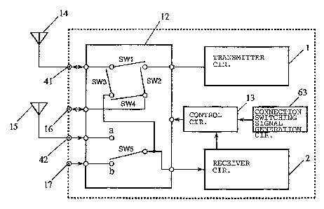
As shown in Fig. 1, a mobile station according to a
first embodiment of the invention includes a transmitter
circuit 1, a receiver circuit 2, an antenna terminal 41 to
which a transmission/reception antenna 14 is connected, an
antenna terminal 42 to which a reception antenna 15 is
connected, an input/output external connector terminal 16, an
input external connector terminal 17, a switch circuit 12 for
switching among modes of connection between the terminals 41,
- 6 -
2188509
42, 16, and 17 and the transmitter and receiver circuits 1 and
2, and a control circuit 13 for controlling the switching
operation of the switch circuit 12.
The switch circuit 12 has four switch elements SW1-SW4
for switching between the transmission/reception antenna
terminal 41 and the input/output external connector terminal
16, and a switch element SW5 for .switchinct between the
reception antenna terminal 42 and the input external connector
terminal 17. The switch elements SW1-SW5 are operated (opened
or closed) in accordance with an output signal of the control
circuit 13 to establish a connection between the antenna
terminals 41 and 42 and the external connector terminals 16 and
17, and the transmitter and receiver circuits 1 and 2.
The control circuit 13 on/off-controls or switches the
switch elements SW1-SW5 of the switch circuit 12 as shown in
Fig. 7 in accordance with the transmission/reception operation
timing of the mobile station and a switching signal that is
supplied from a connection switching signal generation circuit
63 and designating a normal communication or an external
connector communication. The switching in accbrdance with the
transmission/reception operation timing is effected by a
switching signal that is generated within the control circuit
13. The switching signal is output from the generation circuit
63 in response to a key operation on the mobile station main
body, for instance.
_ 7 _
2~8850~
- The mobile station operates in the following manner in
a normal communication. During transmission, only the switch
element SW1 is made on being controlled by the control circuit
13, so that a signal that is output from the transmitter
circuit 1 is supplied to the transmission/reception antenna 14
via the switch element SW1. During reception, in the case
where the antenna 14 is selected, only,the switch element SW3
is made on, so that a reception signal is input to the receiver
circuit 2 via the switch element SW3. Where the antenna 15 is
selected, the switch element SW5 selects terminal a, so that a
reception signal is input to the receiver circuit 2 via
terminal a.
The switching between the antennas 14 and 15 in a
receiving operation is effected, for instance, such that the
levels of reception waves coming from the respective antennas
14 and 15 are measured before the reception timing and the
antenna 14 or 15 providing a higher reception wave level is
selected.
The mobile station operates in the following manner in
an external connector communication. During transmission, only
the switch element SW2 is made on, so that a signal that is
output from the transmitter circuit 1 is supplied to the
external connector terminal 16 via the switch element SW2.
During reception, the switch element SW5 selects terminal b, so
that a reception signal coming from the external connector
terminal 17 is supplied to the receiver circuit 2 via terminal
_ g _
_ ' ' 2188509
b. Alternatively, only the switch element SW4 is made on, so
that a reception signal coming from the external connector
terminal 16 is supplied to the receiver circuit 2 via the
switch element SW4.
In this manner, connection between the transmitter and
receiver circuits 1 and 2, and the antenna terminals 41 and 42
and external connector terminals 16 and 17 is effected through
only one switch element in the switch circuit 12. Therefore,
this mobile station can reduce the signal loss . In particular,
in the transmission side, the output power of the transmitter
circuit can be reduced as much, contributing to reduction in
power consumption.
Embodiment 2
A mobile station according to a second embodiment has
a function of switching between signal paths in a transmitter
circuit in accordance with the operation mode of the mobile
station.
As, shown in Fig. 2, a transmitter circuit la has a
first filter 50 for suppressing unnecessary wave components of
a transmission signal, and isolator 51 for passing a
transmission signal and prohibiting passage of a signal
traveling in the opposite direction, a first amplifier 52 for
amplifying a transmission signal, and a second filter 56 for
suppressing unnecessary wave components of a reception signal.
The transmitter circuit la further has first and second switch
elements 53 and 54 (SW6 and SW7) for connecting terminals c and
_ g _
21885nq
a or terminals d and a during transmission and for connecting
terminals d and f during reception, a second amplifier 55 for
amplifying a transmission signal, a modulator 60 for modulating
a transmission signal, and a transmission signal processing
section 61. The other part of the configuration of this mobile
station is the same as in the first embodiment.
In this mobile station,. the switch elements SW1-SW5 in
the switch circuit 12 and the switch elements SW6 and SW7, all
of which are controlled by the control circuit 13, are on/off-
controlled or switched as shown in Fig. 8 in accordance with
the operation mode (mode switching means 62), the
transmission/reception operation timing of the mobile station,
and a switching signal that is supplied from the connection
switching signal generation circuit 63.
In mode 1 (see Fig. 8), the mobile station operates in
the following manner. During transmission in a normal
communication, the switch element SW1 is made on and the switch
elements SW6 and SW7 connect terminals c and e. A transmission
signal that has been output from the modulator 60 is output
from the transmitter circuit la via the second amplifier 55,
first amplifier 52, isolator 51, and first filter 50, and then
supplied to the antenna 14 via the switch circuit 12. During
reception, the mobile station operates in the same manner as in
the first embodiment.
During transmission in an external connector
communication, the switch element SW2 is made on and the switch
- 10 -
-- 2188508
elements SW6 and SW7 connect terminals c and e, so that a
signal that has been output from the transmitter circuit la is
supplied to the input/output external connector terminal 16.
During reception, the mobile station operates in the same
manner as in the first embodiment.
In mode 2 (see Fig. 8), the mobile station operates in
the following manner. During transmission in a normal
communication, the switch element SW1 is made on and the switch
elements SW6 and SW7 connect terminals d and e. A transmission
signal that has been output from the modulator 60 is output
from the transmitter circuit la via the amplifier 55 and the
second filter 56 for suppressing unnecessary wave components of
the transmission signal, and then supplied to the antenna 14
via the switch element SW1. During reception, the switch
element SW1 is made on and the switch elements SW6 and SW7
connect terminals d and f. A reception signal coming from the
antenna 14 is first supplied, via the switch element SW1, to
the transmitter circuit la, where unnecessary wave components
are suppressed by the second filter 56. After passing through
the switch elements SW6 and SW7, the reception signal is input
to the receiver circuit 2.
In an external connector communication, during each of
transmission and reception, the mobile station operates in the
same manner as in the case of using the antenna 14 except that
the switch element SW1 is made off and the switch element SW2
is made on.
- 11 -
218850
As described above, in this mobile station, switching
among modes of connection between the transmitter and receiver
circuits la and 2, and the antenna terminals 41 and 42 and
external connector terminals 16 and 17 can be performed by
controlling the on/off or switching states of the switch
elements SW1-SW5 in the switch circuit 12. Further, switching
between the paths in the transmitter circuit la can be
performed in accordance with the operation mode setting and the
operation timing. Therefore, this mobile station can be used
for a dual-mode communication of TDMA-TDD (mode 2 ) and TDMA-FDD
(mode 1).
Embodiment 3
In a mobile station according to a third embodiment of
the invention, the switch elements are switched in response to
connection of an external device to the external connector
terminals.
As shown in Fig. 3, this mobile station is equipped
with external connector terminal connection detecting circuits
57 and 58 for detecting connection of an external device to the
external connector terminals 16 and 17, respectively. The
other part of the configuration of this mobile station is the
same as in the second embodiment.
The external connector terminal connection detecting
circuits 57 and 58 detect whether an external device is
connected to the external connector terminals 16 and 17,
respectively, and supply a signal to the control circuit 13
- 12 -
2i8850~
accordingly. The control circuit 13 on/off-controls or
switches the switch elements SW1-SW5 in the switch circuit 12
and the switch elements SW6 and SW7 as shown in Fig. 8. Upon
reception of a signal indicating connection of an external
device from one of the external connector terminal connection
detecting circuits 5? and 58, the control circuit 13
establishes a connection state for an external connector
communication .
With the above configuration, in a normal
communication, this mobile station operates in the same manner
as in the second embodiment. Upon connection of an external
device to one of the external connector terminals 16 and 17,
the mobile station detects it and automatically establishes a
connection state for an external connector communication
without the need of a switching signal from the connection
switching signal generation circuit 63, unlike the case of the
first and second embodiments. Therefore, the switching
elements SW1-SW7 can be switched to effect connection to the
external connector terminal 16 or 17 by a single manipulation
of attaching an external device, thus simplifying manipulations
on the mobile station.
Embodiment 4
A mobile station according to a fourth embodiment of
the invention is featured by an optical communication function.
As shown in Fig. 4, this mobile station is equipped
with a signal output light-emitting element section 24 for
- 13 -
~~885Q9
transmitting an optical signal, and a signal input
photodetecting element section 25 for receiving an optical
signal. The other part of the configuration of this mobile
station is the same as in the second embodiment.
In this mobile station, the switch elements SW1-SW7 are
switched as shown in Fig. 9 in accordance with its operation
mode. In model, the switching of the switch elements SW1-SW7
and the signal flow are the same as in the second embodiment
except that the external connector terminal 16 cannot receive
a signal though it can transmit a signal. This is because the
light-emitting element section 24 has only the transmission
function for optical communication.
In mode 2, the switches SW1-SW7 are controlled in the
same manner as in the second embodiment except for a case of
receiving a signal by the photodetecting element section 25.
That is, a signal received by the photodetecting element
section 25 is supplied to the receiving section 2 via the
switch elements SW5, SW4, and SW2.
In this manner, this mobile station can perform a dual-
mode communication of TDMA-TDD and TDMA-FDD as well as optical
communication by properly switching among the antenna terminals
and the optical communication element sections.
Embodiment 5
A mobile station according to a fifth embodiment of the
invention is featured by a broadcast receiving function.
- 14 -
-- 218850
As shown in Fig. 5, the mobile station is equipped with
an antenna 28 for receiving an AM or FM broadcast signal as
well as a single external connector terminal 29. The other
part of the configuration of this mobile station is the same as
in the second embodiment.
In this mobile station, the switch elements SW1-SW7 are
switched as shown in Fig . 10 in, accordance with the type of its
operation. This mobile station operates in the same manner as
in the second embodiment except that the transmission/reception
external connector terminal 16 of the second embodiment is
replaced by the AM/FM broadcast reception antenna 28 that is
dedicated to reception.
During reception of an AM or FM broadcast signal in
mode 1, the switch circuit 12 is so controlled that only the
switch element SW4 is made on. In mode 2, the control circuit
13 is so controlled that the switch element SW2 is made on and
the switch elements SW6 and SW7 connect terminals d and f,
whereby a signal coming from the broadcast reception antenna 28
is supplied to the receiver circuit 2 via the transmitter
circuit la.
Thus, this mobile station have functions of dual-mode
communication of TDMA-TDD and TDMA-FDD, AM/FM broadcast
reception, and connection to an external device via the
external connector terminal.
- 15 -