Note : Les descriptions sont présentées dans la langue officielle dans laquelle elles ont été soumises.
CA 02188590 1996-10-22
H 1059 PCT
A refill cartridge for a stick which applies product by
rubbing onto a surface and a method for filling the car-
tridge
Field of the Invention
This invention relates to a refill cartridge for a
stick which applies product by rubbing onto a surface, such
as an adhesive stick.
Background of the Invention
Refill cartridges of the field of the present
invention, and a corresponding method for filling them
are known from applicants' DE 41 20
969 A1 and also from DE 41 16 581 A1. They are particular-
ly suitable for refilling adhesive sticks, but also other
sticks which apply product by rubbing onto a surface, such
as deodorant sticks, lipsticks, lubricant sticks, shaving
soap sticks or crayons. The main advantage of these refill
cartridges is that, when the stick is empty, its key non-
consumable elements can be repeatedly reused by quasi-
refilling of the stick with a refill cartridge, for which
purpose the initially closed refill cartridge is fitted
onto and secured to the stick, the screwthreaded spindle of
the stick being introduced into the refill cartridge and
screwed into the plunger so that it can then engage in the
,~'
CA 02188590 1996-10-22
H 1059 PCT 2
bore formed over the entire length of the product of the
refill cartridge.
Summary of the Invention
Although a refill cartridge of the type in question
has considerable advantages, it has been found that the
production and filling of such a refill cartridge with
initially liquid product involve disadvantages in view of
the need to form a bore throughout the product to receive
the screwthreaded spindle. Thus, in the method according
to DE 41 20 969 Al, the empty refill cartridge closed at
its bottom end is initially introduced into a mold in which
a pin extending over the mold - for receiving the screw-
threaded bore of the plunger and for forming the bore
extending throughout the product - is arranged at the
bottom of the mold concentrically of its longitudinal axis.
The product is then poured in and, after the product has
solidified, the pin forming the bore in the product has to
be removed. The refill cartridge then has to be tightly
closed at both ends to ensure that the product does not
come into contact with the surrounding air.
Accordingly, the problem addressed by the present
invention is to enable a refill cartridge of the type in
question to be produced and filled more easily and to
remain satisfactorily sealed after filling.
In a refill cartridge of the type mentioned at the
25 beginning, the solution provided by one embodiment of the
invention includes a tube-like element releasably
closed at its free end by a sealingly fitted cap-like
closure element, the cap-like closure element being inter-
nally formed with a pin-like projection which fills the
30 bore extending throughout the product.
A refill cartridge designed in this way is much easier
to make and to fill. Thus, the product may initially be
poured in liquid form into the refill cartridge closed at
its bottom end, after which the cap-like closure element is
35 sealingly fitted, with the pin-like projection forming the
CA 02188590 1996-10-22
H 1059 PCT 3
desired bore in the product while it is still in the liquid
state. The length of the pin-like projection is
such that a bore extending over the entire length of the
product is formed. When the refill cartridge is used by
the consumer, the cap-like closure element merely has to
be removed from the refill cartridge, thus uncovering the
bore extending through the solid product.
In one particularly advantageous embodiment, the
length of the pin-like projection is such that the free end
l0 thereof engages at least locally in the screwthreaded bore
of the plunger in the fully fitted state of the cap-like
closure element. This ensures that even the screwthreaded
bore of the plunger is substantially free from product so
that, when the refill cartridge is used, the screwthreaded
spindle of the pin can readily be screwed in.
In another particularly advantageous embodiment, the
cap-like closure element and/or the outer receiving zone of
the tube-like element for the cap-like closure element
is/are provided with co-operating, encircling stop means
which are designed in such a way that, before the stop
means cross over one another, the pin-like projection
penetrates fully through the product. In this way, the
required full-length screwthreaded bore can be produced in
two stages by initially loosely applying the closure cap
with its pin-like projection after filling product for
the purpose of air equalization, with the pin-like
projection being centered by the cap-like closure element
and by the entry of the tip of the pin-:like projection
into the screwthreaded part of the plunger. After the
product has cooled, a sealing closure and, at the same
time, further penetration of the pin-like projection into
the screwthreaded part of the plunger are achieved by
application of pressure of the cap-like closure element
and by crossing of the stop means over one another, with
small amounts of filling in the region of the screwthread
bore being laterally displaced past the tip of the
CA 02188590 1996-10-22
H 1059 PCT 4
pin-like projection.
In another particularly advantageous embodiment, the
cap-like closure element is flexible and the pin-like
projection is rigid, in order to establish
an effective seal between the cap-like closure element and
the tube-like element of the refill cartridge and, on the
other hand, to enable the pin-like projection to penetrate
satisfactorily through the product,
To avoid accumulations of material, the cap-like
l0 closure element and the pin-like projection are preferably
in two parts designed to be releasably interconnected.
Another particularly advantageous embodiment 'is
characterized in that the screwthreaded bore of the plunger
and/or the associated opening in the bottom of the tube-
like element are covered by a protective film or the like.
The protective film or thin zone in the bottom of the
container~seals off the refill cartridge from outside,
while the protective film in the region of the
screwthreaded bore of the piston ensures that when the
liquid product is poured in, it cannot pass completely
into and thus block the bore.
Depending on the filling materials, the free end of
the pin-like projection may advantageously be pointed,
conical or stepped.
In another advantageous embodiment, the tube-like
element is externally provided with at least one longitudi
nal groove. This longitudinal groove co-operates with a
fillet internally provided on the tube element of the stick
and affords protection against rotation, as known from Fig.
6 of DE 41 16 581 A1.
To solve the problem stated at the beginning, the
invention also provides a method for filling a refill
cartridge of the type described in the foregoing with
initially liquid and subsequently solidifying product, in
which product is poured into the plunger-equipped refill
,~
CA 02188590 1996-10-22
H 1059 PCT 5
cartridge closed at its bottom end. This method being
characterized in that, after the product has been poured
in and before it solidifies, the cap-like closure element
is fitted onto the corresponding end of the tube-like
element in such a way that the pin-like projection pene
trates fully into the liquid product to form a bore.
In one particularly advantageous embodiment, the cap-
like closure element is initially fitted onto the tube-like
element to such an extent that the free end of the pin-like
projection only projects into the region of the screw-
threaded bore of the plunger and, after solidification of
the product, the cap-like closure element is fully and
sealingly fitted onto the tube-like element by crossing of
the stop means over one another. In this way, air equaliz-
ation, i.e. an outward escape of air, can initially occur
during filling, following which the refill cartridge is
tightly closed after solidification of the product.
Brief Description of the Drawings
The invention is described in more detail in the
following with reference to the accompanying drawings,
in which like items are identified by the same reference
designation, wherein:
Figure 1 is a section through a refill cartridge
according to one embodiment of the invention during
fitting onto a stick.
Figure 2 shows the refill cartridge during filling.
Figure 3 shows the refill cartridge after filling
during the fitting of a cap-like closure element for one
embodiment of the invention.
Figure 4 shows the refill cartridge in its fully
closed state.
Figure 5 shows an embodiment of the cap-like closure
element.
Figures 6 and 7 show embodiments of the free
end of the pin-like projection of the cap-like closure
element.
CA 02188590 1996-10-22
~ ,
5a
Detailed Description of the Invention
A refill cartridge according to the invention for a
stick which applies product by rubbing onto a surface is
globally denoted by the reference 1 in the drawings. In
CA 02188590 1996-10-22
x 1059 PcT s
the illustrated embodiment, the refill cartridge 1 is
intended for an adhesive stick, forming part of the ad-
hesive stick after fitting or joining thereto. According-
ly, the adhesive stick as a whole, including the. refill
cartridge 1, is denoted by the reference 2. Besides ad-
hesive sticks, a refill cartridge according to the inven-
tion is also suitable for other product sticks designed to
apply a small amount of product onto a surface by rubbing
on that surface, for example deodorant sticks, lipsticks,
lubricant sticks, shaving soap sticks or crayons. In the
interests of clarity, however, the following description
refers solely to an adhesive stick or adhesive product,
but is not meant to limit the invention thereto.
Apart from the refill cartridge 1, which is part of
the adhesive stick 2, the adhesive stick 2 comprises a tube
element 3 with a continuous base 4 which merges into an
encircling snap-action fastening 5 far receiving a knurled
nut 6 with a screwthreaded spindle 7 projecting upwards
from the tube element 3. The tube element 3 widens upwards
towards one end. This region is denoted by the reference
3a and is provided internally with an internal screwthread
8 for securing the corresponding end of the refill car-
tridge 1, for which purpose the ref ill cartridge 1 is
provided with a corresponding outer thread 9.
The refill cartridge 1 itself comprises a tube-like
element 1 with a substantially continuous base 11 Which is
centrally provided with a thin zone, a push-through zone or
the like denoted by the reference 22 in Fig. 2. Arranged
inside the refill cartridge 1 is a longitudinally displace-
able plunger 12 with a screwthreaded bore 13 which is non-
rotatably guided in the tube-like element 10 (not shown in
detail), the screwthreaded bore 13 corresponding with the
outer screwthread 14 of the screwthreaded spindle 7 of the
adhesive stick 1. Above the plunger 12, the tube-like
element 10 of the refill cartridge 1 is filled with an
adhesive product 15 which is provided over its entire
CA 02188590 1996-10-22
2., /~~, ~9~
H 1059 PCT 8
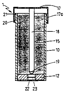
While the adhesive 15 is still liquid, the cap-like
closure element 17 is fitted onto the tube-like element 10
of the refill cartridge from above, as shown in Fig. 3, in
such a way that the stop means 20,21 come into contact with
one another without crossing so that the sealing side wall
region 17a of the cap-like closure element 17 does not yet
seal off the refill cartridge 1 at its upper end. At the
same time, the pin-like projection 18 of the cap-like
closure element 17 penetrates centrally into the liquid
product 15 and, acting as a core, forms the desired bore 16
throughout the product 15. Through the choice of a suit-
able length for the pin-like projection 18, the free end'19
of the pin-like projection penetrates slightly into the
screwthreaded bore 13 and is centered therein.
When the adhesive 15 has hardened sufficiently, the
cap-like closure element 17 is fully applied by crossing of
the stop means 20 over the stop means 21 so that, on the
one hand, tight closure of the upper end of the refill
cartridge 1 is guaranteed, because the stop means 20,21
bear tightly against one another, and on the other hand the
free end 19 of the pin-like projection 18 penetrates so far
into the screwthreaded bore 13 that any residues of adhe-
sive present there are pushed aside.
Accordingly, the refill cartridge 1 is ready for use
through formation of the bore 16 extending throughout the
product 15 and may be marketed in this form.
If, now, the refill cartridge 1 - as part of an
adhesive stick 2 - is fixed to the adhesive stick 2, as
shown in Fig. l, the cap-like closure element 17 is
removed and the tube-like closure element l0 of the refill
cartridge 1 is screwed onto the tube element 3 of the
adhesive stick 2. At the same time, the screwthreaded
spindle 7 of the adhesive stick 2, after penetrating the
thin zone 22 and the protective film 23, enters the screw-
threaded bore 13 of the plunger 12 of the refill cartridge
1 so that the product 15
;t
. CA 02188590 1996-10-22
I
H 1059 PCT 9
is able to pass through the bore 16 without difficulty.
A closure cap may then be applied to the tube-like
element to at its upper end in order to seal off the tube-
like element 10.
In one particular embodiment, the cap-like closure
element 17 itself may be used as the closure cap providing,
as shown in Fig. 5, the cap-like closure element 17 and the
pin-like projection 18 are in two parts releasably joined
to one another. To this end, the cap-like closure element
l0 17, as shown in Fig. 5, is internally provided with a
central cylindrical projection 24 with an encircling stop
bead 25 onto which the hollow pin-like projection 18 'is
designed to fit via a corresponding inner bead 26. If,
now, the pin-like projection 18 is removed from the cap-
like closure element 17, the cap-like closure element 17
may be used as a closure cap for the adhesive stick 2.
The cap-like closure element 17 is preferably made of
a flexible plastic, while the pin-like projection 18 is
rigid which guarantees effective sealing of the tube-like
element 10 by the cap-like closure element 17, and
satisfactory formation of the bore 16 in the adhesive
product 15 by the pin-like projection 18.
Depending on the products used, the free end 19 of the
pin-like projection 18 of the cap-like closure element 17
may assume various forms. In the embodiments shown in
Figs. 2 to 5, the free end 19 is pointed whereas, in the
embodiment shown in Fig. 6, the free end 19a is conical.
In the embodiment shown in Fig. 7, the free end 19b is
stepped.
In addition to the embodiment shown in Fig. 1, the
tube-like element 10 of the refill cartridge 1 may be
externally provided with longitudinal grooves which co-
operate with longitudinal fillets (not shown) on the inside
of the tube element 3 and stop the tube-like element 10
from rotating in the tube element 3, as known in detail
CA 02188590 1996-10-22
2, ~~38, ~ ~w
H 1059 PCT 10
from DE 41 16 581 A1 and described therein with reference
to Fig. 6 of the drawings. Through this additional anti
rotation measure, which has not been shown in the drawings,
the refill cartridge 1 can be introduced into the tube
element 3 without difficulty.
The invention is not of course confined to the illus-
trated embodiments. Further embodiments of the invention
are possible without departing from the basic concept. For
example, the connection between the cap-like closure ele-
went 1? and the tube-like element 10 of the refill car-
tridge 1 may assume a different form and may even consist,
for example, of a screw connection or the like. Such
further embodiments, which may be recognized by those of
skill in the art, are meant to be covered by the spirit
and scope of the appended claims.