Sélection de la langue

Search

Sommaire du brevet 2189578 

Énoncé de désistement de responsabilité concernant l'information provenant de tiers

Une partie des informations de ce site Web a été fournie par des sources externes. Le gouvernement du Canada n'assume aucune responsabilité concernant la précision, l'actualité ou la fiabilité des informations fournies par les sources externes. Les utilisateurs qui désirent employer cette information devraient consulter directement la source des informations. Le contenu fourni par les sources externes n'est pas assujetti aux exigences sur les langues officielles, la protection des renseignements personnels et l'accessibilité.

Disponibilité de l'Abrégé et des Revendications

L'apparition de différences dans le texte et l'image des Revendications et de l'Abrégé dépend du moment auquel le document est publié. Les textes des Revendications et de l'Abrégé sont affichés :

  • lorsque la demande peut être examinée par le public;
  • lorsque le brevet est émis (délivrance).
(12) Brevet: (11) CA 2189578
(54) Titre français: CONNECTEUR ELECTRIQUE A ARTICULATION
(54) Titre anglais: HINGED ELECTRICAL CONNECTOR
Statut: Périmé et au-delà du délai pour l’annulation
Données bibliographiques
(51) Classification internationale des brevets (CIB):
  • H01R 04/40 (2006.01)
  • H01R 04/44 (2006.01)
  • H01R 11/15 (2006.01)
(72) Inventeurs :
  • POLIDORI, MARIO (Etats-Unis d'Amérique)
(73) Titulaires :
  • THOMAS P. POLIDORI
(71) Demandeurs :
  • THOMAS P. POLIDORI (Etats-Unis d'Amérique)
(74) Agent: BORDEN LADNER GERVAIS LLP
(74) Co-agent:
(45) Délivré: 2000-07-18
(22) Date de dépôt: 1996-11-04
(41) Mise à la disponibilité du public: 1997-05-21
Requête d'examen: 1996-11-04
Licence disponible: S.O.
Cédé au domaine public: S.O.
(25) Langue des documents déposés: Anglais

Traité de coopération en matière de brevets (PCT): Non

(30) Données de priorité de la demande:
Numéro de la demande Pays / territoire Date
08/560,970 (Etats-Unis d'Amérique) 1995-11-20

Abrégés

Abrégé français

Un connecteur électrique comprend un premier élément de mâchoire possédant une surface interne, une surface externe, un premier et un deuxième bout. Le premier élément de mâchoire possède une portion courbe formée sur la surface interne adjacente au premier bout. Un deuxième élément de mâchoire possède une surface interne, une surface externe, un premier et un deuxième bout. Le deuxième élément de mâchoire possède une portion courbe formée sur la surface interne adjacente au premier bout. Une borne se présentant sous forme d'un étrier est fixée entre les deuxièmes bouts des premier et deuxième éléments de mâchoire. L'étrier présente un écart qui le traverse. Un élément de butée fait saillie du deuxième bout du premier élément de mâchoire. L'élément de butée est positionné dans l'écart de l'étrier afin d'empêcher tout déplacement axial de ce dernier le long du connecteur électrique.


Abrégé anglais

An electrical connector includes a first jaw member that has an inside surface, an outside surface, a first end and a second end. The first jaw member further has a curved portion formed on the inside surface adjacent the first end. A second jaw member has an inside surface, an outside surface, a first end and a second end. The second jaw member also has a curved portion formed on the inside surface adjacent the first end. A terminal in the form of a stirrup is secured between the second ends of the first and second jaw members. The stirrup has a gap formed therethrough. Projecting from the second end of the first jaw member is a stop member. The stop member is positioned between the gap in the stirrup in order to prevent axial movement of the same along the electrical connector.

Revendications

Note : Les revendications sont présentées dans la langue officielle dans laquelle elles ont été soumises.


WHAT IS CLAIMED IS:
1. An electrical connector for facilitating the
connection between an energized line and a tap line
comprising:
a first metal jaw member having an inside
surface, an outside surface, a first end and a second end,
said first jaw member having a curved portion formed on
said inside surface adjacent said first end, said first jaw
member further having a first hinge means positioned
adjacent said second end thereof;
a second metal jaw member having an inside
surface, an outside surface, a first end and a second end,
said second jaw member having a curved portion formed on
said inside surface adjacent said first end, said second
jaw member further having a second hinge means positioned
adjacent said second end thereof;
a metal stirrup secured between said first and
second hinge means, said stirrup having a gap formed
therein, and
stop means on one of said jaw members and
positioned in said gap in said stirrup for preventing
lateral movement of said stirrup.
2. The electrical connector of claim 1 further
including fastener means for urging said first end of said
first jaw member towards said first end of said second jaw
member.
3. The electrical connector of claim 2 wherein
said fastener means includes a threaded hole formed through
said first jaw member, a hole formed through said second
jaw member and a bolt having a predetermined diameter, said
bolt passing through said hole in said second jaw member
and threadably engageable in said threaded hole of said
first jaw member so that rotation of said bolt causes said
first ends of said first and second jaw members to converge
towards one another.

4. The electrical connector of claim 3 wherein
said hole formed through said second jaw member has a
cross-sectional area which is substantially larger than
said diameter of said bolt.
5. An electrical connector for facilitating the
connection between an energized line and a tap line
comprising:
a first metal jaw member having an inside
surface, an outside surface, a first end and a second end,
said first jaw member having a curved portion formed on
said inside surface adjacent said first end, said first jaw
member further having a first hinge means positioned
adjacent said second end thereof and defined by a plurality
of spaced apart finger pairs;
a second metal jaw member having an inside
surface, an outside surface, a first end and a second end,
said second jaw member having a curved portion formed on
said inside surface adjacent said first end, said second
jaw member further having a second hinge means positioned
adjacent said second end thereof and defined by a plurality
of spaced apart finger pairs, and
a stirrup comprised of an elongated conductor
formed into a substantially closed loop, said stirrup
having a circular cross-section and having a portion nested
in said spaced apart finger pairs of said first and second
jaw members.
6. The electrical connector of claim 5 wherein
at least some of said spaced apart finger pairs of said jaw
members extend around said portion of said stirrup more
than 180°.
7. The electrical connector of claim 5 wherein
said portion of said stirrup has a gap formed therein and
wherein said electrical connector includes a stop means
projecting inwardly and being positioned within said gap
for preventing axial movement of said stirrup along said
electrical connector.

8. The electrical connector of claim 7 further
including fastener means for urging said first end of said
first jaw member towards said first end of said second jaw
member.
9. The electrical connector of claim 8 wherein
said fastener means includes a threaded hole formed through
said first jaw member, a hole formed through said second
jaw member and a bolt having a predetermined diameter, said
bolt extending through said hole in said second jaw member
and being threadably engagable in said threaded hole of
said first jaw member so that rotation of said bolt causes
said first ends of said first and second jaw members to
converge towards one another.
10. The electrical connector of claim 9 wherein
said hole formed through said second jaw member has a
cross-sectional area which is substantially larger than
said diameter of said bolt.

Description

Note : Les descriptions sont présentées dans la langue officielle dans laquelle elles ont été soumises.

2~ 89~78
HINGED ELECTRICAL CONNECTOR
Background of the Invention
The present invention is directed toward a hinged
electrical connector and, more particularly, to such a
connector that is secured to a high tension wire to provide
a terminal so that energy from the wire can be directed to
an electrical device.
Oftentimes it is necessary to tap electricity off
a high tension wire and direct it to an electrical device
such as a transformer. In order to tap the electricity, a
connector must be utilized between the high tension wire
and one end of a conductive cable. Different size
connectors must, of course, be utilized for different sized
high tension wires. As a result, a workman must either
climb a utility pole or utilize a "cherry picker" or other
mechanical lifting mechanism in order to get close enough
to the high tension line to secure the connector thereto.
This obviously creates significant danger.
In lieu of connecting a conductive cable directly
to the high tension line, devices have been employed which
include a connector and a terminal and wherein the terminal
can then be utilized to provide electrical current to the
electrical device to be energized. Frequently, such
terminals are in the shape of a stirrup which presents a
convenient terminal of uniform size that can be easily
utilized by a workman. Another connector secured to the end
of the cable can then be used to connect the cable to the
high tension line through the stirrup. Since the stirrup is
of uniform size, the connectors can be pre-selected and be
of the type that are capable of being connected to the
stirrup from a distance utilizing an extension pole or the
like. When utilizing these combined connectors and
stirrups, it is important that the electrical connector be

218957~
easily and firmly secured to the high tension wire and that
the stirrup be held securely in place.
Summary of the Invention
It is an object of the present invention to
provide an electrical connector that can be readily and
firmly secured to a high tension wire.
It is another object of the invention to provide
such a connector that furnishes a terminal in order to
facilitate the transfer of energy from the high tension
wire to an electrical device.
In accordance with the illustrative embodiments,
demonstrating features and advantages of the present
invention, there is provided a hinged electrical connector
which includes a first jaw member that has an inside
surface, an outside surface, a first end and a second end.
The first jaw member has a curved portion formed on the
inside surface adjacent the first end. A second jaw member
has an inside surface, an outside surface, a first end and
a second end. The second jaw member also has a curved
portion formed on the inside surface adjacent the first
end. A ter~in~l in the form of a stirrup is secured between
the second ends of the first and second jaw members. The
stirrup has a gap formed therethrough. Projecting from the
second end of the first jaw member is a stop member. The
stop member is positioned between the gap in the stirrup in
order to prevent axial movement of the same along the
electrical connector.
Other objects, features and advantages of the
invention will be readily apparent from the following
detailed description of a preferred embodiment thereof
taken in conjunction with the drawings.

2~8g~78
Brief Description of the Drawings
For the purpose of illustrating the invention,
there is shown in the accompanying drawings one form which
is presently preferred; it being understood that the
invention is not intended to be limited to the precise
arrangements and instrumentalities shown.
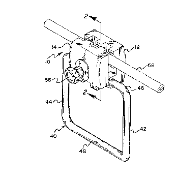
Figure 1 is a perspective view of the present
invention;
Figure 2 is a side cross-sectional view taken
along the lines 2-2 of Figure l;
Figure 3 is a view similar to Figure 2 showing
the jaw members pivoted away from one another;
Figure 4 is a partial side perspective view with
the first jaw member cut away;
Figure 5 is a partial side perspective view with
the second jaw member cut away, and
Figure 6 is a cross-sectional view taken along
lines 6-6 of Figure 5.
Detailed Description of the Preferred Embodiment
Referring now to the drawings in detail wherein
like reference numerals have been used throughout the
various figures to designate like elements, there is shown
in the figures a hinged electrical connector constructed in
accordance with the principles of the present invention and
designated generally as 10.
The electrical connector 10 includes first and
second jaw members 12 and 14, respectively. The jaw members
are preferably comprised of stainless steel. However, they
can be comprised of a variety of other conductive metals
and metal alloys. First jaw member 12 includes a first end
16 and a second end 18 (Figure 5) and second jaw member 14
similarly includes a first end 20 and a second end 22
(Figure 4). Spaced apart curved portions 24 extend inwardly

2~89578
from the inside surface of the first jaw member 12 adjacent
the first end 16 thereof (Figure 5J. Similarly, spaced
apart curved portions 26 extend inwardly from the inside
surface of the second jaw member 14 adjacent the first end
20 thereof (Figure 4).
Extending inwardly from the second end 18 of the
first jaw member 12 are a plurality of spaced apart pairs
of fingers 28, 30 and 32. In the preferred embodiment, a
stop member 34 projects inwardly from the center of finger
pair 30 as illustrated in Figure 6. Similarly, spaced apart
finger pairs 36 and 38 extend inwardly from the second end
22 of the second jaw member 14.
Referring to Figure 1, a stirrup 40 in the form
of a substantially closed loop is shown. The stirrup 40
includes a pair of opposing sides 42 and 44 and a pair of
opposing ends 46 and 48. The stirrup is secured between the
jaw members 12 and 14 in the following manner. The stop
member 34 of finger pair 30 is positioned through a gap 50
formed in end 46 of the stirrup 40 (Figure 6). Finger pair
36 of the second jaw member 14 is then positioned between
finger pairs 28 and 30 of the first jaw member 12.
Similarly, finger pair 38 is positioned between finger
pairs 30 and 32. Accordingly, the end 46 of the stirrup is
correspondingly nested in the finger pairs 28, 30 and 32 so
that the sides 42 and 44 of the stirrup extend outwardly
from the connector 10. In the preferred embodiment, each of
the spaced apart finger pairs 28, 30 and 32 extends more
than 180~ around the end 46 of the stirrup 40.
The free ends of the finger pairs 28, 30, 32, 36
and 38 are then swaged together thereby causing the hinged
securement of the jaw members 12 and 14 with the stirrup
serving as a pintle. The stop member 34 secures the stirrup
40 in place so that axial movement is prevented.
In the preferred embodiment, a threaded hole 52
is formed through the center of the first jaw member 12
(Figures 5 and 6). An elongated bolt hole 54 is formed
through the center of the second jaw member 14 (Figure 4).

21~9~78
The elongated bolt hole 54 is preferably flared outward
from the inside surface of the second jaw member 14 to the
outside surface thereof. A shear head bolt 56 is adapted to
be positioned through the elongated bolt hole 54 and
threadably engaged in the threaded hole 52. The elongated
hole 54, formed in the second jaw member 14, is
significantly larger than the diameter of the bolt 56.
In order to facilitate an understanding of the
principles associated with the foregoing apparatus, its
operation will now be briefly described. The first ends 16
and 20 of the jaw members 12 and 14 are separated from one
another a sufficient distance to allow a conductor 58, such
as a high tension wire, to fit therebetween. Since the
elongated hole 54 formed in the second jaw member 14 is
significantly larger than the diameter of the bolt 56, the
first end of the jaw member 14 can be separated a
significant distance from the first end of the jaw member
12 while one end of the bolt 56 remains threaded through
the bolt hole 52 in the first jaw member 12. This permits
the electrical connector to be secured to a high tension
wire that has a relatively large diameter. Thereafter, the
hinged electrical connector 10 is positioned adjacent the
high tension wire (see Figure 1). The high tension wire 58
is then placed between spaced apart curved portions 24 and
26 on the first and second jaw members 12 and 14,
respectively. The high tension wire is firmly secured to
the hinged electrical connector 10 by threading the bolt 56
further into threaded hole 52 thereby causing the first
ends 16 and 20 of the first and second jaw members to
converge toward one another and be firmly clamped onto the
high tension wire.
The connector 10 is secured to the high tension
wire so that energy from the wire can be tapped from the
same and delivered to another an electrical device such as
a transformer. More specifically, the stirrup 40 serves as
a terminal through which electricity can be trapped. A lead
or tap line (not shown) can have one end clamped to the

2189578
stirrup and another end secured to the electrical device so
that electricity can be provided to the device.
The present invention may be embodied in other
specific forms without departing from the spirit or
essential attributes thereof and accordingly reference
should be made to the appended claims rather than to the
foregoing specification as indicating the scope of the
invention .

Dessin représentatif
Une figure unique qui représente un dessin illustrant l'invention.
États administratifs

2024-08-01 : Dans le cadre de la transition vers les Brevets de nouvelle génération (BNG), la base de données sur les brevets canadiens (BDBC) contient désormais un Historique d'événement plus détaillé, qui reproduit le Journal des événements de notre nouvelle solution interne.

Veuillez noter que les événements débutant par « Inactive : » se réfèrent à des événements qui ne sont plus utilisés dans notre nouvelle solution interne.

Pour une meilleure compréhension de l'état de la demande ou brevet qui figure sur cette page, la rubrique Mise en garde , et les descriptions de Brevet , Historique d'événement , Taxes périodiques et Historique des paiements devraient être consultées.

Historique d'événement

Description Date
Le délai pour l'annulation est expiré 2016-11-04
Lettre envoyée 2015-11-04
Inactive : CIB de MCD 2006-03-12
Accordé par délivrance 2000-07-18
Inactive : Page couverture publiée 2000-07-17
Déclaration du statut de petite entité jugée conforme 2000-04-12
Préoctroi 2000-04-12
Inactive : Taxe finale reçue 2000-04-12
Lettre envoyée 1999-10-20
Un avis d'acceptation est envoyé 1999-10-20
Inactive : Approuvée aux fins d'acceptation (AFA) 1999-09-29
Inactive : Renseign. sur l'état - Complets dès date d'ent. journ. 1998-04-21
Inactive : Dem. traitée sur TS dès date d'ent. journal 1998-04-21
Demande publiée (accessible au public) 1997-05-21
Toutes les exigences pour l'examen - jugée conforme 1996-11-04
Exigences pour une requête d'examen - jugée conforme 1996-11-04

Historique d'abandonnement

Il n'y a pas d'historique d'abandonnement

Taxes périodiques

Le dernier paiement a été reçu le 1999-10-07

Avis : Si le paiement en totalité n'a pas été reçu au plus tard à la date indiquée, une taxe supplémentaire peut être imposée, soit une des taxes suivantes :

  • taxe de rétablissement ;
  • taxe pour paiement en souffrance ; ou
  • taxe additionnelle pour le renversement d'une péremption réputée.

Les taxes sur les brevets sont ajustées au 1er janvier de chaque année. Les montants ci-dessus sont les montants actuels s'ils sont reçus au plus tard le 31 décembre de l'année en cours.
Veuillez vous référer à la page web des taxes sur les brevets de l'OPIC pour voir tous les montants actuels des taxes.

Historique des taxes

Type de taxes Anniversaire Échéance Date payée
Requête d'examen - petite 1996-11-04
TM (demande, 2e anniv.) - petite 02 1998-11-04 1998-10-14
TM (demande, 3e anniv.) - petite 03 1999-11-04 1999-10-07
Taxe finale - petite 2000-04-12
TM (brevet, 4e anniv.) - petite 2000-11-06 2000-11-02
TM (brevet, 5e anniv.) - petite 2001-11-05 2001-10-09
TM (brevet, 6e anniv.) - petite 2002-11-04 2002-10-10
TM (brevet, 7e anniv.) - petite 2003-11-04 2003-10-07
TM (brevet, 8e anniv.) - petite 2004-11-04 2004-10-05
TM (brevet, 9e anniv.) - petite 2005-11-04 2005-10-31
TM (brevet, 10e anniv.) - petite 2006-11-06 2006-10-13
TM (brevet, 11e anniv.) - petite 2007-11-05 2007-10-09
TM (brevet, 12e anniv.) - générale 2008-11-04 2008-10-22
TM (brevet, 13e anniv.) - générale 2009-11-04 2009-10-06
TM (brevet, 14e anniv.) - générale 2010-11-04 2010-10-26
TM (brevet, 15e anniv.) - générale 2011-11-04 2011-10-12
TM (brevet, 16e anniv.) - générale 2012-11-05 2012-10-10
TM (brevet, 17e anniv.) - générale 2013-11-04 2013-10-04
TM (brevet, 18e anniv.) - générale 2014-11-04 2014-10-03
Titulaires au dossier

Les titulaires actuels et antérieures au dossier sont affichés en ordre alphabétique.

Titulaires actuels au dossier
THOMAS P. POLIDORI
Titulaires antérieures au dossier
MARIO POLIDORI
Les propriétaires antérieurs qui ne figurent pas dans la liste des « Propriétaires au dossier » apparaîtront dans d'autres documents au dossier.
Documents

Pour visionner les fichiers sélectionnés, entrer le code reCAPTCHA :


Pour visualiser une image, cliquer sur un lien dans la colonne description du document (Temporairement non-disponible). Pour télécharger l'image (les images), cliquer l'une ou plusieurs cases à cocher dans la première colonne et ensuite cliquer sur le bouton "Télécharger sélection en format PDF (archive Zip)" ou le bouton "Télécharger sélection (en un fichier PDF fusionné)".

Liste des documents de brevet publiés et non publiés sur la BDBC .

Si vous avez des difficultés à accéder au contenu, veuillez communiquer avec le Centre de services à la clientèle au 1-866-997-1936, ou envoyer un courriel au Centre de service à la clientèle de l'OPIC.

({010=Tous les documents, 020=Au moment du dépôt, 030=Au moment de la mise à la disponibilité du public, 040=À la délivrance, 050=Examen, 060=Correspondance reçue, 070=Divers, 080=Correspondance envoyée, 090=Paiement})


Description du
Document 
Date
(aaaa-mm-jj) 
Nombre de pages   Taille de l'image (Ko) 
Abrégé 1997-03-24 1 24
Revendications 1997-03-24 3 112
Description 1997-03-24 6 246
Dessins 1997-03-24 2 63
Dessin représentatif 2000-07-05 1 10
Dessin représentatif 1997-08-20 1 14
Rappel de taxe de maintien due 1998-07-06 1 115
Avis du commissaire - Demande jugée acceptable 1999-10-19 1 164
Avis concernant la taxe de maintien 2015-12-15 1 171
Correspondance 2000-04-11 1 30