Sélection de la langue

Search

Sommaire du brevet 2189608 

Énoncé de désistement de responsabilité concernant l'information provenant de tiers

Une partie des informations de ce site Web a été fournie par des sources externes. Le gouvernement du Canada n'assume aucune responsabilité concernant la précision, l'actualité ou la fiabilité des informations fournies par les sources externes. Les utilisateurs qui désirent employer cette information devraient consulter directement la source des informations. Le contenu fourni par les sources externes n'est pas assujetti aux exigences sur les langues officielles, la protection des renseignements personnels et l'accessibilité.

Disponibilité de l'Abrégé et des Revendications

L'apparition de différences dans le texte et l'image des Revendications et de l'Abrégé dépend du moment auquel le document est publié. Les textes des Revendications et de l'Abrégé sont affichés :

  • lorsque la demande peut être examinée par le public;
  • lorsque le brevet est émis (délivrance).
(12) Brevet: (11) CA 2189608
(54) Titre français: MANOCONTACT A ZONE MORTE ACCRUE
(54) Titre anglais: PRESSURE SWITCH WITH INCREASED DEADBAND
Statut: Durée expirée - au-delà du délai suivant l'octroi
Données bibliographiques
Abrégés

Abrégé français

Manocontact doté d'un logement avec un alésage intérieur s'étendant d'une extrémité à l'autre. Une tige coulissante dans l'alésage et fonctionnant par pression extérieure de liquide s'étend entre un piston à une extrémité du logement et un commutateur électrique à fonctionnement mécanique à l'autre extrémité du logement. Un ressort est disposé autour de la tige entre une première butée sur la tige et une seconde butée sur le logement. Le ressort fournit une résistance contre le mouvement de la tige sous la pression extérieure. La résistance du ressort au mouvement est réglée par un manche engageant le ressort, le manche étant fileté dans l'alésage du logement pour un mouvement longitudinal dans le logement. Un anneau ouvert est coincé entre les deux autres anneaux résiste au mouvement de la tige vers le mouvement longitudinal.


Abrégé anglais

A pressure switch has a housing with an interior bore extending from one end to the other. A rod slidable within the bore and operated by external fluid pressure extends between a piston at one end of the housing and a mechanically operated electrical switch at the other end of the housing. A spring is disposed about the rod between a first stop on the rod and a second stop on the housing. The spring provides resistance against movement of the rod under external pressure. The resistance of the spring to movement is adjusted by a sleeve engaging the spring, with the sleeve threaded into the bore of the housing for movement longitudinally within the housing. A split ring wedged between two other rings resists movement of the rod to longitudinal movement.

Revendications

Note : Les revendications sont présentées dans la langue officielle dans laquelle elles ont été soumises.


7
THE EMBODIMENTS OF THE INVENTION IN WHICH AN EXCLUSIVE
PROPERTY OR PRIVILEGE IS CLAIMED ARE DEFINED AS
FOLLOWS:
1. A pressure switch comprising:
a housing with an interior bore;
a rod slidable over a limited range within
the bore under external fluid pressure;
a mechanically operated electrical switch
operatively connected to the rod;
a spring disposed within the housing and
oriented to resist movement of the rod within the
bore;
adjustment means encapsulated within the
housing to adjust resistance of the rod to movement
under the external fluid pressure; and
means to increase resistive forces tending
to oppose longitudinal movement of the rod within the
bore.
2. The pressure switch of claim 1 in which the
means to increase resistance includes:
a split ring disposed around the rod; and
means to force the split ring radially
inward upon movement of the rod under external
pressure acting on the pressure switch.
3. The pressure switch of claim 2 in which the
means to force the ring radially inward includes:
the split ring having a central portion and
at least a bevelled first edge, the bevelled first
edge tapering radially inward in a longitudinal
direction away from the central portion; and

8
a second ring disposed about the rod, the
second ring having an edge complementary to the
bevelled first edge, such that longitudinal forces on
the second ring are translated at least in part to
radially directed forces on the split ring.
4. The pressure switch of claim 3 in which the
split ring has a bevelled second edge on a side
opposed to the bevelled first edge, the bevelled
second edge tapering radially inward in a longitudinal
direction away from the central portion of the split
ring; and
the pressure switch further including a
third ring disposed about the rod on the side of the
split ring opposed to the second ring, the third ring
having an edge complementary to the bevelled second
edge, such that longitudinal forces on the third ring
are translated at least in part to radially directed
forces on the split ring.
5. The pressure switch of claim 1 in which the
means to increase resistive forces on the rod is
disposed between the spring and a shoulder on the
housing.
6. The pressure switch of claim 2 in which the
split ring and the means to force the split ring
radially inward are disposed between the spring and a
shoulder on the housing.
7. The pressure switch of claim 3 in which the
split ring and the second ring are disposed between
the spring and a shoulder on the housing.

9
8. The pressure switch of claim 4 in which the
split ring and the third ring are disposed between the
spring and a shoulder on the housing.

Description

Note : Les descriptions sont présentées dans la langue officielle dans laquelle elles ont été soumises.

2189E08
1
TITLE OF THE INVENTION:
Pressure Switch with Increased Deadband
NAME OF INVENTOR:
James Richard Ellett
FIELD OF THE INVENTION
This invention relates to pressure switches.
BACKGROUND AND SUMMARY OF THE INVENTION
In the design of pressure switches, a rod
slidable within a housing and movable by changes in
external fluid pressure operates a plunger of a
mechanically operated electrical switch. Resistance of
the rod to movement, and hence the pressure at which
the switch trips, is adjusted by a spring within the
pressure switch that is biased against movement of the
rod due to external fluid pressure. Adjustment of the
compression on the spring changes the tripping
pressure, which for example may be set at 500 psi. As
the pressure reduces, hysteresis in the system arising
for example from friction in the switch, hysteresis in
the spring and free travel of the mechanically
operated switch causes the switch to reset at a lower
pressure than the tripping pressure, for example at
450 psi. The difference between the tripping and reset
pressure is known as the deadband.
SUMMARY OF THE INVENTION
It is sometimes, however, desirable to have
a greater deadband. This invention provides a manner
of increasing the deadband of prior art switches. In
a switch of the type described in the background of
the invention, there is provided according to one

2
aspect of the invention means to increase resistive
forces tending to oppose longitudinal movement of the
rod within the bore. In a further aspect of the
invention, the means to increase resistive forces
includes a split ring disposed around the rod and
wedged between two whole rings, such that compression
of the whole rings causes the split ring to
frictionally engage the rod.
Selection of the angle of the wedge angle
between the rings allows selection of the deadband. A
smaller wedge angle means a greater deadband.
These and other aspects of the invention are
described in the detailed description and claims that
follow.
BRIEF DESCRIPTION OF THE DRAWINGS
There will now be described preferred
embodiments of the invention, with reference to the
drawings, by way of illustration, in which like
numerals denote like elements and in which:
Fig. 1 is a longitudinal section through a
prior art pressure switch;
Fig. 2 is a longitudinal section through a
pressure switch according to the invention; and
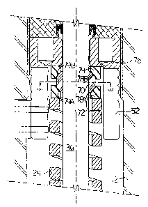
Fig. 3 is a cross-section along the line 3-3
of Fig. 2.
DETAILED DESCRIPTION OF PREFERRED EMBODIMENTS
A pressure switch made by Argus Machine C0.
Ltd. of Edmonton, Alberta, Canada, is illustrated in
Fig. 1, which shows a longitudinal section of a
pressure switch 10. The pressure switch 10 is formed
of a housing 12 having a first end 14 and a second end
16 threaded together and sealed with seals 13. Set

2189bt~~
3
screw 17 locks the first end 14 and second end 16 of
the housing together. A bore 18 of variable inner
diameter passes through the housing 12 from the first
end 14 to the second end 16. In the bore 18 at the
first end 14 is a piston 22 that is free to move
longitudinally a limited amount within the bore 18.
The piston 22 is shown here as including a piston head
24 snugly fitted in piston guide 26 at the first end
14 of the housing 12. The piston guide 26 is formed in
two pieces (upper 26a and lower 26b) and is secured
within the housing by a locking nut 28 threaded in the
first end of the housing 12. Four laterally extending
slots 25 in the top end of upper piece 26a of the
piston guide 26 allow for draining of fluid. Two of
the slots 25 are shown. The other two are at right
angles to the section of Fig. 1. End 20 of the bore 18
is sealed by diaphragm 30 that is held firmly within
the end l4 by the piston guide 26 and housing 12 and
sealed with a gasket 32 or a suitable alternative such
as a seal ring. A support disc 92 is interposed
between the diaphragm 30 and piston 22 and assists in
supporting the diaphragm 30 against collapse from
external fluid pressure. Range of movement of the
piston is limited by shoulders on the piston guide 26
and by shoulders on the piston 22.
A mechanically operated electrical switch 34
(micro-switch) is disposed at the second end 16 of the
housing 12. A rod 36 is mounted slidably within the
housing 12 and extends between the piston 22 and the
mechanically operated electrical switch 34. By direct
contact with the piston 22 and plunger 38 of the
switch 34, the rod 36 is operatively connected to both
the piston 22 and the switch 34, but this operative
connection may be accomplished using intervening

4
devices, with added complexity. The diaphragm 30,
piston 22 and rod 36 function as a mechanism to
transfer external fluid pressure along rod 36 to the
mechanically operated electrical switch 34. The
mechanically operated electrical switch is operated by
a plunger 38, which abuts against hub 39 threaded onto
the end 37 of rod 36. Movement of the rod 36 and hub
39 in the direction from the first end of the housing
12 to the second end depresses the plunger 38 and
activates the switch 34. The end 37 of the rod 36 is
sealed within the bore 18 by elastomer seals 40.
A spring 42 is disposed about the rod 36
between a first stop 44 on the rod 36 and a second
stop 54 forming part of the adjustment sleeve 52. The
spring 42 provides resistance against movement of the
rod 36 from the first end 14 of the housing 12 to the
second end 16 of the housing 12. The degree of
resistance of the spring 42 to external fluid pressure
on piston 22, hence movement of rod 36, is adjustable
by an adjustment sleeve 52 surrounding and thus
engaging one end of the spring 42: The sleeve 52
includes a threaded portion 54 threaded into the bore
18 of the housing 12 at threads 19 for movement
longitudinally within the housing 12 by rotation of
the sleeve 52. Plural radially extending slots 56 are
disposed around the sleeve 52 and are shaped to
receive an implement, such as a screw driver, used to
rotate the sleeve 52. A port 58 or opening in the
housing 12 is provided and makes the adjustment sleeve
52 accessible, for example by a screwdriver or other
means for operating the adjustment sleeve 52. A cover
60 for the port 58 is provided by wring 62 disposed
around the housing 12 and threaded onto the housing 12
over the port 58.

2i896~8
The invention shown in Figs . 2 and 3 is used
on the switch shown in Fig. 1. Except as indicated
below, the parts of the pressure switch 10 used in
Figs. 2 and 3 may be the same as shown in Fig. 1 or
5 any other pressure switch having a spring biased rod
that actuates a mechanical switch. Spring 42 is
disposed within the housing 12 and oriented to resist
movement of the rod 36 within the bore 18. Sleeve 52
is encapsulated within the housing 12 and may be
rotated to adjust resistance of the rod 36 to movement
under external fluid pressure towards the mechanically
operated switch 34. To increase resistive forces on
the rod 36, which prevents tripping of the switch 34
until higher pressures but also increases the deadband
of the switch, a split ring 70 is disposed around the
rod 36 and sandwiched between two rings 72 and 74. The
ring set formed of rings 70, 72 and 74 is prevented
from longitudinal movement towards the switch 34 by a
shoulder 76 on the sleeve 52, and the spring 42 acts
against the ring set.
The ring set, under pressure of the spring
42, acts to increase resistive forces tending to
oppose movement of the rod 36 within the bore 18
towards and away from the mechanically operated switch
34. The split ring 70 has opposed bevelled edges 78A
and 78B that taper radially inwardly' away from the
center of the split ring. The rings 72 and 74 have
corresponding bevelled edges 79A and 79B that are
complementary to the edges 78A and 78B. Pressure from
the spring 42 urges the rings 72 and 74 together so
that they tend to ride up onto the split ring 70. As
the rings 72 and 74 are whole, they cannot diverge
radially outward, and thus the split ring 70 is forced
inward by the rings 72 and 74 to contract about the

21 X39608
6
rod 36. Hence longitudinal forces on the rings 72 and
74 are converted to radial forces on the split ring
70. The split ring 70 thus tends to grip the rod 36
and move with it. The split ring 70 is stopped from
longitudinal movement towards the switch 34 by the
shoulder 76 on adjustment sleeve 52, and away from the
switch by the spring 42. The drag on the rod 36 caused
by the split ring 70 gripping the rod 36 thus
increases resistance of the rod 36 to movement
longitudinally within the bore 18.
As a result, the use of the ring set
illustrated in Figs . 2 and 3 serves to increase the
deadband of the switch. Increasing the angle of the
bevelled edges ( in relation to an axis parallel to the
rod) tends to decrease the deadband. For example an
angle of 22° for the bevelled edges 78A, 78B, 79A, 79B
in an exemplary embodiment has produced a deadband of
200 psi, while an angle of 30° has produced a deadband
of 150 psi and an angle of 45° has produced a deadband
of 100 psi. Since the use of the rings 70-74 tends to
increase the tripping pressure, for a given tripping
pressure, the compression on the spring 42 should be
adjusted.
A person skilled in the art could make
immaterial modifications to the invention described
and claimed in this patent without departing from the
essence of the invention.

Dessin représentatif
Une figure unique qui représente un dessin illustrant l'invention.
États administratifs

2024-08-01 : Dans le cadre de la transition vers les Brevets de nouvelle génération (BNG), la base de données sur les brevets canadiens (BDBC) contient désormais un Historique d'événement plus détaillé, qui reproduit le Journal des événements de notre nouvelle solution interne.

Veuillez noter que les événements débutant par « Inactive : » se réfèrent à des événements qui ne sont plus utilisés dans notre nouvelle solution interne.

Pour une meilleure compréhension de l'état de la demande ou brevet qui figure sur cette page, la rubrique Mise en garde , et les descriptions de Brevet , Historique d'événement , Taxes périodiques et Historique des paiements devraient être consultées.

Historique d'événement

Description Date
Exigences relatives à la nomination d'un agent - jugée conforme 2020-04-22
Exigences relatives à la révocation de la nomination d'un agent - jugée conforme 2020-04-22
Inactive : Périmé (brevet - nouvelle loi) 2016-11-05
Inactive : Lettre officielle 2007-07-13
Demande visant la nomination d'un agent 2007-07-09
Demande visant la révocation de la nomination d'un agent 2007-07-09
Accordé par délivrance 2004-02-24
Inactive : Page couverture publiée 2004-02-23
Inactive : Taxe finale reçue 2003-12-10
Préoctroi 2003-12-10
Un avis d'acceptation est envoyé 2003-06-18
Lettre envoyée 2003-06-18
Un avis d'acceptation est envoyé 2003-06-18
Inactive : Approuvée aux fins d'acceptation (AFA) 2003-05-28
Inactive : Dem. traitée sur TS dès date d'ent. journal 1999-10-13
Lettre envoyée 1999-10-13
Inactive : Renseign. sur l'état - Complets dès date d'ent. journ. 1999-10-13
Toutes les exigences pour l'examen - jugée conforme 1999-09-23
Exigences pour une requête d'examen - jugée conforme 1999-09-23
Demande publiée (accessible au public) 1998-05-05

Historique d'abandonnement

Il n'y a pas d'historique d'abandonnement

Taxes périodiques

Le dernier paiement a été reçu le 2003-10-21

Avis : Si le paiement en totalité n'a pas été reçu au plus tard à la date indiquée, une taxe supplémentaire peut être imposée, soit une des taxes suivantes :

  • taxe de rétablissement ;
  • taxe pour paiement en souffrance ; ou
  • taxe additionnelle pour le renversement d'une péremption réputée.

Veuillez vous référer à la page web des taxes sur les brevets de l'OPIC pour voir tous les montants actuels des taxes.

Titulaires au dossier

Les titulaires actuels et antérieures au dossier sont affichés en ordre alphabétique.

Titulaires actuels au dossier
ARGUS MACHINE CO. LTD.
Titulaires antérieures au dossier
JAMES RICHARD ELLETT
Les propriétaires antérieurs qui ne figurent pas dans la liste des « Propriétaires au dossier » apparaîtront dans d'autres documents au dossier.
Documents

Pour visionner les fichiers sélectionnés, entrer le code reCAPTCHA :


Pour visualiser une image, cliquer sur un lien dans la colonne description du document. Pour télécharger l'image (les images), cliquer l'une ou plusieurs cases à cocher dans la première colonne et ensuite cliquer sur le bouton "Télécharger sélection en format PDF (archive Zip)" ou le bouton "Télécharger sélection (en un fichier PDF fusionné)".

Liste des documents de brevet publiés et non publiés sur la BDBC .

Si vous avez des difficultés à accéder au contenu, veuillez communiquer avec le Centre de services à la clientèle au 1-866-997-1936, ou envoyer un courriel au Centre de service à la clientèle de l'OPIC.


Description du
Document 
Date
(aaaa-mm-jj) 
Nombre de pages   Taille de l'image (Ko) 
Dessin représentatif 1998-05-19 1 14
Dessin représentatif 2003-05-13 1 12
Description 1997-04-03 6 247
Page couverture 1997-04-03 1 15
Abrégé 1997-04-03 1 22
Revendications 1997-04-03 3 74
Dessins 1997-04-03 2 66
Page couverture 1998-05-19 1 54
Page couverture 2004-01-20 2 46
Rappel de taxe de maintien due 1998-07-07 1 115
Accusé de réception de la requête d'examen 1999-10-13 1 178
Avis du commissaire - Demande jugée acceptable 2003-06-18 1 160
Correspondance 1996-12-04 1 28
Taxes 2003-10-21 1 26
Correspondance 2003-12-10 1 25
Taxes 1998-10-22 1 37
Taxes 2002-11-01 1 25
Taxes 2004-10-06 1 26
Taxes 2005-10-20 1 26
Taxes 2006-11-01 1 26
Correspondance 2007-07-09 2 59
Correspondance 2007-07-13 1 14
Correspondance 2007-07-13 1 17
Taxes 2007-08-02 1 26
Taxes 2008-10-29 1 30
Taxes 2009-10-09 1 28