Sélection de la langue

Search

Sommaire du brevet 2189684 

Énoncé de désistement de responsabilité concernant l'information provenant de tiers

Une partie des informations de ce site Web a été fournie par des sources externes. Le gouvernement du Canada n'assume aucune responsabilité concernant la précision, l'actualité ou la fiabilité des informations fournies par les sources externes. Les utilisateurs qui désirent employer cette information devraient consulter directement la source des informations. Le contenu fourni par les sources externes n'est pas assujetti aux exigences sur les langues officielles, la protection des renseignements personnels et l'accessibilité.

Disponibilité de l'Abrégé et des Revendications

L'apparition de différences dans le texte et l'image des Revendications et de l'Abrégé dépend du moment auquel le document est publié. Les textes des Revendications et de l'Abrégé sont affichés :

  • lorsque la demande peut être examinée par le public;
  • lorsque le brevet est émis (délivrance).
(12) Brevet: (11) CA 2189684
(54) Titre français: DISPOSITIF DE TRANSPORT DE RECIPIENTS DE BOISSON A COLLET PIVOTANT
(54) Titre anglais: BEVERAGE CONTAINER HOLDER WITH PIVOTING COLLAR
Statut: Périmé et au-delà du délai pour l’annulation
Données bibliographiques
(51) Classification internationale des brevets (CIB):
  • B60N 03/10 (2006.01)
  • B60R 07/04 (2006.01)
(72) Inventeurs :
  • COOLEY, ROBERT MERLE (Etats-Unis d'Amérique)
(73) Titulaires :
  • DEERE & COMPANY
(71) Demandeurs :
  • DEERE & COMPANY (Etats-Unis d'Amérique)
(74) Agent: BORDEN LADNER GERVAIS LLP
(74) Co-agent:
(45) Délivré: 1999-07-06
(22) Date de dépôt: 1996-11-05
(41) Mise à la disponibilité du public: 1997-05-30
Requête d'examen: 1996-11-05
Licence disponible: S.O.
Cédé au domaine public: S.O.
(25) Langue des documents déposés: Anglais

Traité de coopération en matière de brevets (PCT): Non

(30) Données de priorité de la demande:
Numéro de la demande Pays / territoire Date
08/564,528 (Etats-Unis d'Amérique) 1995-11-29

Abrégés

Abrégé anglais


A container holder assembly includes a housing which
forms a generally cylindrical recess and a shelf surface which
extends radially outwardly from an upper end of the recess. A
sector shaped collar member is pivotally coupled to the
housing and is pivotal from a first position wherein it is
oriented away from the shelf surface and to a second position
wherein it at least partially overlaps the shelf surface. The
collar member and the shelf surface form an opening
therebetween which is smaller than the upper end of the recess
when the collar member is in the first position. The collar
has a tab which is received in slots in outer wall which
extends around the open end of the recess.

Revendications

Note : Les revendications sont présentées dans la langue officielle dans laquelle elles ont été soumises.


The embodiments of the invention in which an exclusive
property or priviledge is claimed are defined as follows:
1. A container holder assembly comprising:
a housing comprising a generally cylindrical housing wall
enclosing a recess, the housing wall having a lower first end
joined to a bottom surface and an open upper second end, the
housing also forming a shelf surface extending radially
outwardly from the second end of the housing wall; and
a sector shaped collar member pivotally coupled to the
housing, the collar member being pivotal from a first position
wherein it is oriented away from the shelf surface and to a
second position wherein it at least partially overlaps the
shelf surface, the collar member and the shelf surface forming
an opening therebetween which is smaller than the open second
end of the recess when the collar member is in said first
position.
2. The container holder assembly of claim 1, wherein:
the housing forms a curved outer wall extending from a
lower end to an upper free end, the outer wall lower end being
joined to an outer edge of the shelf surface and to the housing
wall second end.
3. The container holder assembly of claim 2, wherein:
first and second slots are formed in the outer wall, the
first and second slots being oriented on opposite sides of the
assembly; and
the collar member has a tab which projects outwardly from
a central part thereof, the tab being received by the first
slot when the collar member is in the first position, and the
tab being received by the second slot when the collar member is
in the second position.
4. The container holder assembly of claim 1, wherein:
the housing wall forms a first side wall member having an
upper end and a lower end, a second side wall member having an
upper end and a lower end, the bottom surface being joined to

the lower ends of the first and second side wall members, the
first and second side wall members being joined together to
form the recess, and the first side wall member having a larger
radius of curvature than a radius of curvature of the second
side wall member.
5. The container holder assembly of claim 4, wherein:
the shelf surface is joined to an upper edge of the second
side wall member.
6. The container holder assembly of claim 4, wherein:
the shelf surface has an outer radius of curvature
substantially the same as a radius of curvature of the first
side wall member.
7. The container holder assembly of claim 4, wherein:
the collar member has an inner radius of curvature which
is less than the radius of curvature of the first wall member.
8. The container holder assembly of claim 4, wherein:
the collar member has an outer radius of curvature which
is substantially the same as the radius of curvature of the
first wall member.
9. A container holder assembly comprising:
a first side wall member having an upper end and a lower
end;
a second side wall member having an upper end and a lower
end;
a bottom wall joined to the lower ends of the first and
second side wall members, the first and second side wall
members and the bottom wall being joined together to form a
recess;
a sector shaped shelf member attached to and extending
radially outwardly from the upper end of the second side wall
member; and
a sector shaped collar member pivotally coupled to the
wall members, the collar member being pivotal from a first
position wherein it is oriented towards the first side wall

member and to a second position wherein it engages the shelf
member.
10. The container holder assembly of claim 9, comprising:
a further side wall member, the further wall member being
partially cylindrical and extending substantially axially from
a lower end to an upper free end, the further side wall member
lower end being joined to an outer edge of the shelf member and
to the upper end of the first side wall member;
first and second slots formed in the further wall member,
the first and second slots being oriented on opposite sides of
the assembly; and
the collar member has a tab which projects outwardly from
a central part thereof, the tab being received by the first
slot and engaging the first wall member when the collar member
is in the first position, and the tab being received by the
second slot when the collar member is in the second position.
11. The container holder assembly of claim 9, wherein:
the first side wall member has a larger radius of
curvature than a radius of curvature of the second side wall
member.
12. The container holder assembly of claim 9,
the first and second side wall members are joined together
along a first plane which is parallel to an axis of the recess.
13. The container holder assembly of claim 12, wherein:
the shelf member has an outer radius of curvature
substantially the same as a radius of curvature of the first
side wall member.
14. The container holder assembly of claim 9, further
comprising:
a third wall, the third wall extending from a lower end to
an upper free end, the third wall lower end being joined to an
outer edge of the shelf member and to the upper end of the
first side wall member.
15. The container holder assembly of claim 14, wherein

the third wall comprises:
a first wall part, the first wall part being partially
cylindrical and extending substantially axially from a lower
end to an upper free end, the first wall part lower end being
joined to an outer edge of the shelf member and to the upper
end of the first side wall member; and
a second wall part, the second wall part being partially
cylindrical and extending substantially axially from a lower
end to an upper free end, the second wall part lower end being
joined to an outer edge of the shelf member and to the upper
end of the first side wall member, the first and second wall
parts being spaced apart on opposite sides of the assembly, the
first wall member and the first and second wall parts forming a
first slot therebetween, the second wall member and the first
and second wall parts forming a second slot therebetween, the
first and second slots being oriented on opposite sides of the
assembly.
16. The container holder assembly of claim 15, wherein:
the collar member has a tab which projects outwardly from
a central part thereof, the tab being received by the first
slot and engaging the first wall member when the collar member
is in the first position and the tab being received by the
second slot and the second wall member when the collar member
is in the second position.
17. A holder assembly comprising:
a first side wall member having an upper end and a lower
end;
a second side wall member having an upper end and a lower
end, the first and second side wall members being joined
together along a first plane to form a generally cylindrical
recess with an axis parallel to the first plane, the first side
wall member having a radius of curvature which is larger than a
radius of curvature of the second side wall member;
a bottom wall joined to the lower ends of the first and

second side wall members;
a sector shaped shelf member attached to and extending
radially outwardly from the upper end of the second side wall
member, the shelf member having an outer radius of curvature
substantially the same as the radius of curvature of the first
side wall;
a third side wall member, the third wall member being
partially cylindrical and extending substantially axially from
a lower end to an upper free end, the third side wall member
lower end being joined to an outer edge of the shelf member and
to the upper end of the first side wall member;
a fourth side wall member, the fourth wall member being
partially cylindrical and extending substantially axially from
a lower end to an upper free end, the fourth side wall member
lower end being joined to an outer edge of the shelf member and
to the upper end of the first side wall member, the third and
fourth wall members being spaced apart on opposite sides of a
second plane which is perpendicular with respect to the first
plane, the first, third and fourth wall members forming a first
slot therebetween, the second, third and fourth wall members
forming a second slot therebetween, first and second slots
being oriented on opposite sides of the first plane; and
a sector shaped collar member pivotally coupled to the
wall members along a pivot axis which is parallel to the first
plane, the collar member having a tab which projects outwardly
from a central part thereof, the collar member being pivotal
from a first position wherein the tab is received by the first
slot and engages the first wall member to a second position
wherein the tab is received by the second slot and engages the
second wall member.

Description

Note : Les descriptions sont présentées dans la langue officielle dans laquelle elles ont été soumises.

2189684
BEVERAGE CONTAINER HOLDER WITH PIVOTING COLLAR
Backqround of the Invention
The invention relates to a vehicle accessory for
receiving and holding items such as beverage containers.
It is desirable to provide a holder for receiving
containers of different sizes, such as soft drink cans and
bottles and coffee mugs. Various designs have been proposed
in attempts to solve this problem. For example, U.S. Pat. No.
5,102,085 shows a container holder which has a hollow
cylindrical insert which slides within a cylindrical base.
However, when the insert is extended to receive a tall
container, the container must fit through a narrower opening
in the bottom of the insert. U.S. Pat. No. 5,326,064 and U.S.
Pat. No. 4,721,216 both show drink holders with a larger
diameter upper section and a smaller diameter lower section.
However, with such holders a tall narrow container may be
susceptible to tipping because it would be held only at its
bottom end. It would be desirable to have a container holder
which is simple in construction and which securely
accommodates a wide variety of containers.
Summary of the Invention
Accordingly, an object of this invention is to provide a
beverage container holder which can securely and conveniently
hold a range of container sizes and types.
These and other objects are achieved by the present
invention, wherein a container holder assembly includes a
housing which forms a generally cylindrical recess and a shelf
surface which extends radially outwardly from an upper end of
the recess. A sector shaped collar member is pivotally
coupled to the housing and is pivotal from a first position
wherein it is oriented away from the shelf surface and to a
second position wherein it at least partially overlaps the
shelf surface. The collar member and the shelf surface form
an opening therebetween which is smaller than the upper end of
the recess when the collar member is in the first position.
The collar has a tab which is received in slots in an outer
wall which extends around the open end of the recess.
~ I

~189684
-
Brief Description of the Drawings
Fig. 1 is a top view of a container holder assembly
according to the present invention;
Fig. 2 is a sectional view taken along lines 2-2 of FIG.
1; and
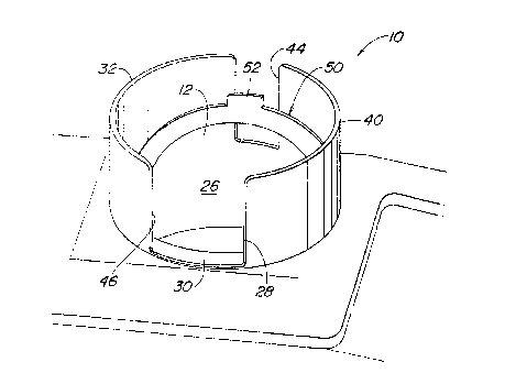
Fig. 3 is a perspective view of a container holder
assembly according to the present invention.
Detailed Description
Referring to the Figures, a holder assembly includes a
housing 10 which forms a first larger radius of curvature side
wall member 12 having an upper end 14 and a lower end 16, and
a second smaller radius of curvature side wall member 18
having an upper end 20 and a lower end 22. The first and
second side wall members 12 and 18 are joined together by
radially and axially extending walls 13 and 19 along a first
plane 24 to form a generally cylindrical recess 26 with an
axis parallel to the first plane 24. A bottom wall 28 is
joined to the lower ends of the first and second side wall
members 12 and 18.
The housing 10 also forms a sector shaped shelf member 30
which is extends radially outwardly and through an angle of
approximately 180 degrees from the upper end 20 of the second
side wall member 18. The shelf member 30 has an outer radius
of curvature which is substantially the same as the radius of
curvature of the first side wall 12 and an inner radius of
curvature which is substantially the same as the radius of
curvature of the second side wall 18.
The housing 10 also forms a partially cylindrical third
side wall member 32 which extends substantially axially from a
lower end 34 to an upper free end 36. The lower end 34 is
joined to an outer edge of the shelf member 30 and to the
upper end 14 of the first side wall member 12.
The housing 10 also forms a partially cylindrical fourth
side wall member 40 which also extends substantially axially
from a lower end to an upper free end. The lower end of the
fourth wall member 40 is also joined to an outer edge of the

218968~
shelf member 30 and to the upper end 14 of the first side wall
member 12.
The third and fourth wall members 32, 40 together form a
notched curved wall which substantially surrounds the upper
end of the recess 26 and in effect, axially extends the recess
26. The third and fourth wall members 32, 40 are spaced apart
on opposite sides of a second plane 42 which is perpendicular
with respect to the first plane 24. The first, third and
fourth wall members form a first slot 44 therebetween, and the
shelf member 30 and the third and fourth wall members form a
second slot 46 therebetween. The slots 44 and 46 are oriented
on opposite sides of the first plane 24. Pivot pin holes 47
and 49 are formed in the housing near the plane of the upper
surface of the shelf member 30 and in alignment with the first
plane 24. Slot 46 is preferably larger than slot 44 and is
oriented so as to conveniently receive a finger ring (not
shown) of a beverage mug (not shown).
The holder assembly also includes a sector shaped collar
member 50 which is pivotally coupled to the lower ends of the
third and fourth wall members 32, 40, or to the upper ends of
walls 12 and 18, along a pivot axis which is defined by the
holes 47 and 49. The collar member 50 has sector shaped body
51, a tab 52 which projects outwardly from a central part of
the body 51 and a pair of pivot pins 54, 56 which project
radially outwardly from opposite ends of the body 51 and which
are received by the corresponding holes 47 and 49. The collar
member body 51 has an inner radius of curvature which is less
than the radius of curvature of the first wall member 12 and
which is substantially equal to the radius of curvature of the
second wall member 18. The collar member body 51 has an outer
radius of curvature which is substantially the same as the
radius of curvature of the first wall member 12.
The collar member 50 is pivotal to a first position
(shown by solid lines in FIG. 2), wherein the tab 52 is
received by the first slot 44 and engages the upper end 14 of
first wall member 12, and to a second position (shown by

- 2~8g68~
dashed lines in FIG. 2), wherein the tab 52 is received by the
second slot 46 and engages the upper end shelf member 30.
When the collar member 50 is in its first position the
collar member 50 and the shelf member 30 together form a
nearly complete annular shelf surface which supports a
properly sized mug (not shown) near the top of the holder
assembly for easy access thereto by the person using the mug.
Also when the collar member 50 is in its first position, the
collar member 50 and the shelf member 30 together enclose an
opening therebetween which is smaller than the upper end of
the recess 26 so as to fit closely around a taller narrower
container such as a soft drink bottle (not shown).
Preferably, a finger ring (not shown) of a mug can be
positioned within the larger slot 46.
When the collar member 50 is in its second position the
collar member 50 substantially overlaps the shelf 30 and
increased access to the lower part of recess 26 is provided so
that a taller beverage container, such as a can or bottle (not
shown) may be received by recess 26 and supported by bottom
wall 28.
While the present invention has been described in
conjunction with a specific embodiment, it is understood that
many alternatives, modifications and variations will be
apparent to those skilled in the art in light of the foregoing
description. Accordingly, this invention is intended to
embrace all such alternatives, modifications and variations
which fall within the spirit and scope of the appended claims.

Dessin représentatif
Une figure unique qui représente un dessin illustrant l'invention.
États administratifs

2024-08-01 : Dans le cadre de la transition vers les Brevets de nouvelle génération (BNG), la base de données sur les brevets canadiens (BDBC) contient désormais un Historique d'événement plus détaillé, qui reproduit le Journal des événements de notre nouvelle solution interne.

Veuillez noter que les événements débutant par « Inactive : » se réfèrent à des événements qui ne sont plus utilisés dans notre nouvelle solution interne.

Pour une meilleure compréhension de l'état de la demande ou brevet qui figure sur cette page, la rubrique Mise en garde , et les descriptions de Brevet , Historique d'événement , Taxes périodiques et Historique des paiements devraient être consultées.

Historique d'événement

Description Date
Le délai pour l'annulation est expiré 2002-11-05
Lettre envoyée 2001-11-05
Accordé par délivrance 1999-07-06
Inactive : Page couverture publiée 1999-07-05
Inactive : Taxe finale reçue 1999-03-23
Préoctroi 1999-03-23
Un avis d'acceptation est envoyé 1998-10-28
Lettre envoyée 1998-10-28
Inactive : Approuvée aux fins d'acceptation (AFA) 1998-10-07
Modification reçue - modification volontaire 1998-06-05
Inactive : Renseign. sur l'état - Complets dès date d'ent. journ. 1998-03-27
Inactive : Dem. traitée sur TS dès date d'ent. journal 1998-03-27
Demande publiée (accessible au public) 1997-05-30
Toutes les exigences pour l'examen - jugée conforme 1996-11-05
Exigences pour une requête d'examen - jugée conforme 1996-11-05

Historique d'abandonnement

Il n'y a pas d'historique d'abandonnement

Taxes périodiques

Le dernier paiement a été reçu le 1998-11-04

Avis : Si le paiement en totalité n'a pas été reçu au plus tard à la date indiquée, une taxe supplémentaire peut être imposée, soit une des taxes suivantes :

  • taxe de rétablissement ;
  • taxe pour paiement en souffrance ; ou
  • taxe additionnelle pour le renversement d'une péremption réputée.

Les taxes sur les brevets sont ajustées au 1er janvier de chaque année. Les montants ci-dessus sont les montants actuels s'ils sont reçus au plus tard le 31 décembre de l'année en cours.
Veuillez vous référer à la page web des taxes sur les brevets de l'OPIC pour voir tous les montants actuels des taxes.

Historique des taxes

Type de taxes Anniversaire Échéance Date payée
Requête d'examen - générale 1996-11-05
TM (demande, 2e anniv.) - générale 02 1998-11-05 1998-11-04
Taxe finale - générale 1999-03-23
TM (brevet, 3e anniv.) - générale 1999-11-05 1999-11-04
TM (brevet, 4e anniv.) - générale 2000-11-06 2000-11-03
Titulaires au dossier

Les titulaires actuels et antérieures au dossier sont affichés en ordre alphabétique.

Titulaires actuels au dossier
DEERE & COMPANY
Titulaires antérieures au dossier
ROBERT MERLE COOLEY
Les propriétaires antérieurs qui ne figurent pas dans la liste des « Propriétaires au dossier » apparaîtront dans d'autres documents au dossier.
Documents

Pour visionner les fichiers sélectionnés, entrer le code reCAPTCHA :


Pour visualiser une image, cliquer sur un lien dans la colonne description du document. Pour télécharger l'image (les images), cliquer l'une ou plusieurs cases à cocher dans la première colonne et ensuite cliquer sur le bouton "Télécharger sélection en format PDF (archive Zip)" ou le bouton "Télécharger sélection (en un fichier PDF fusionné)".

Liste des documents de brevet publiés et non publiés sur la BDBC .

Si vous avez des difficultés à accéder au contenu, veuillez communiquer avec le Centre de services à la clientèle au 1-866-997-1936, ou envoyer un courriel au Centre de service à la clientèle de l'OPIC.


Description du
Document 
Date
(aaaa-mm-jj) 
Nombre de pages   Taille de l'image (Ko) 
Revendications 1998-06-04 5 213
Abrégé 1997-04-02 1 21
Revendications 1997-04-02 5 207
Description 1997-04-02 4 189
Dessins 1997-04-02 1 30
Dessin représentatif 1999-06-28 1 10
Dessin représentatif 1998-05-21 1 11
Rappel de taxe de maintien due 1998-07-06 1 115
Avis du commissaire - Demande jugée acceptable 1998-10-27 1 163
Avis concernant la taxe de maintien 2001-12-02 1 178
Correspondance 1999-03-22 1 32