Note : Les descriptions sont présentées dans la langue officielle dans laquelle elles ont été soumises.
2 1 90443
SEGMENTED SMELT SPOUT
BACKGROUND OF THE INVENIION
This invention relates generally to chemical recovery units, and
more specifically, to a smelt spout that is particularly suited for use in a
5 chemical recovery unit for the purpose of effecting thelcwilh the discharge
from the chemical recovery unit of smelt, which is comprised of non-burnable
chemicals and which is produced during the course of the operation of the
chemical recovery units.
Chemical recovery units are steam generators, the furnace of each
10 of which is lined with steam generating tubes. Such chemical recovery units
are employed in the pulp and paper industry wherein the so-called black liquor
produced from the Kraft pulping process is introduced into the furnace of the
chemical recovery unit whereby the combustible, i.e., burnable, materials,
which the black liquor embodies, are burned in the furnace of the chemical
15 recovery unit and whereby the non-burnable chemicals, which the black liquor
embodies, are smelted and as such can be recovered.
In accordance with the mode of operation of such chemical
recovery units the black liquor is sprayed into the furnace of the chemical
recovery unit at a location spaced well above the bottom of the furnace. This
20 black liquor has a substantial moisture content and most of this moisture is
driven from the black liquor spray upon the introduction of the black liquor into
C960990
2 ! 90~43
- 2 -
the furnace of the chemical recovery unit because of the high temperature in thefurnace and the hot gases passing upwardly through the furnace and the spray.
The solids in the black liquor that remain after thus removing the moisture fromthe black liquor fall onto the bottom, i.e., hearth, of the furnace of the chemical
5 recovery unit and form thereat a roughly truncated pile. During the descent tothe hearth of the furnace some of the lighter volatiles are driven from these
solids from which the aforementioned roughly truncated pile is formed, and the
remaining volatiles from these solids are liberated and the combustible
materials in these solids are burned in the aforementioned roughly truncated
1 O pile with this combustion being supported by the introduction of primary air at
locations spaced somewhat above the bottom, i.e., hearth, of the furnace of the
chemical recovery unit. This air is introduced through ports such that this air is
directed generally over and upon the aforementioned roughly truncated pile of
solids. Some burnables, i.e., combustible materials, in these solids are carried1 5 up through the furnace of the chemical recovery unit and are consumed above
the location at which the black liquor is introduced into the furnace ofthe
chemical recovery unit with secondary air being introduced into the filrnace of
the chemical recovery unit for this purpose, i.e., to effect therewith the
consumption, i.e., combustion, of these solids. The non-burnable chemicals,
20 which the black liquor embodies, are on the other hand smelted and
periodically withdrawn from the furnace of the chemical recovery unit by
means of a smelt spout. It is to such a smelt spout that the subject matter of the
instant application is directed.
It has long been known in the prior art to provide smelt spouts
25 that are suitable for use in a chemical recovery unit for the purpose of effecting
therewith the discharge of smelt from the furnace of the chemical recovery unit.By way of exemplification and not limitation, one example of a prior art form
of smelt spout that has heretodate been intended for lltili7~tion in a chemical
C960990
21 ~044~
recovery unit for the purpose of effecting therewith the discharge of smelt fromthe furnace of the chemical recovery unit is that which forms the subject matterof C~n~ n Patent No. 1,235,863 entitled "Steam Cooled Spout," which issued
on May 3, 1988. In accordance with one aspect of the teachings of C~n~ n
5 Patent No. 1,235,863, there is provided a substantially energy saving steam
cooled spout that offers reduced explosion hazards. This substantially energy
saving steam cooled spout includes a substantially heat resistant heat
exch~nging metallic wall, defining a spout for receiving and conveying a smelt
and contacting the smelt against one surface of the heat exchanging metallic
10 wall. A second heat resistant wall joins the heat exchanging metallic wall onthe opposite surface of the heat exchanging metallic wall. The second heat
resistant wall with the opposite surface of the heat exchanging metal wall
defines a passage for a flow of steam along the heat exchanging metallic wall.
A plurality of baffle means are mounted within the aforedescribed passage.
1 5 The plurality of baffle means join the heat exch~nging metallic wall to the
second heat resistant wall so as to thus define a tortuous path in order to thereby
increase the path of the steam over the heat exchanging metallic wall for the
purpose of raising the temperature of the steam. To this end, the tortuous path
is designed to be operative to boost the temperature of the steam in order for the
20 steam to be in a superheated condition, while at the same time cooling the heat
exchanging metallic wall and thereby the smelt, and reducing the stress caused
on the heat exchanging metallic wall by the molten smelt. The aforedescribed
passage at the outlet end thereof is provided with means for directing the flow
of steam in its superheated condition into the flow of molten smelt. The steam
25 being in a superheated condition has minimum explosive expansion
characteristics when in contact with the molten smelt.
Another example, by way of exemplification and not limitation,
of a prior art form of smelt spout that has heretodate been intended for
C960990
21 90443
- 4 -
tili7~tion in a chemical recovery unit for the purpose of effecting therewith the
discharge of smelt from the furnace of the chemical recovery unit is that which
forms the subject matter of Japanese Patent Document No. 03287890, which
was published on December 18, 1991. In accordance with the teachings of
Japanese Patent Document No. 03287890, there is provided a smelt spout that
includes a first portion, which is designed to be contacted by the smelt, and a
second portion within which the aforementioned first portion is designed to be
supported. The first portion comprises a heat resistant and anticorrosive Cr-Ni
based alloy. The second portion comprises either one or both of the following:
a heat insulating and fire resisting layer, and an alumina based ceramic layer.
In the case where both of the aforedescribed layers are employed, the alumina
based ceramic layer is preferably interposed between the Cr-Ni based alloy and
the heat insulating and fire resisting layer.
Still another example, by way of exemplification and not
limitation, of a prior art form of smelt spout that has heretodate been intendedfor ~ltili7~tion in a chemical recovery unit for the purpose of effecting therewith
the discharge of smelt from the furnace of the chemical recovery unit is that
which forms the subject matter of U.S. Patent No. 4,011,047 entitled "Smelt
Spout For Recovery Boiler," which issued on March 8, 1977. In accordance
with the teachings of U.S. Patent No. 4,011,047, there is provided a non-water
cooled smelt spout for a pulp mill chemical recovery furnace. The aforesaid
smelt spout includes a metal trough having bottom and side walls. A lining is
provided in the metal trough for purposes of isolating the smelt from the troughThe metal trough includes an end wall formed at the free, i.e., front, end
thereof. Immediately adjacent the bottom wall of the metal trough there is
provided a stream jet means. The stream jet means is operative for directing
steam away from the spout to intersect the trajectory of the smelt pouring from
the smelt spout for purposes of causing the smelt to disintegrate.
C960990
21 90~43
Still a further example, by way of exemplification and not
limitation, of a prior art form of smelt spout that has heretodate been intendedfor ~ltili7~tion in a chemical recovery unit for the purpose of effecting therewith
the discharge of smelt from the furnace of the chemical recovery unit is that
5 which forms the subject matter of Japanese Patent Document No. 04343786,
which was published on November 30, 1992. In accordance with the teachings
of Japanese Patent Document No. 04343786, there is provided for use in a
chemical recovery boiler a smelt spout, which embodies a chute that is lined
with blocks of ceramic. Preferably, the chute is made of an alloy containing
1 O more than 40% of Cr by weight, and the blocks of ceramic are made of
alumina.
Yet another example, by way of exemplification and not
limitation, of a prior art form of smelt spout that has heretodate been intendedfor lltili7~tion in a chemical recovery unit for the purpose of effecting therewith
1 5 the discharge of smelt from the furnace of the chemical recovery unit is that
which forms the subject matte~ of U.S. Patent No. 5,437,768 entitled "Non-
Baffled Low Pressure Drop Vacuum Cooled Inserted Smelt Spout," which
issued on August 1, 1995. In accordance with the teachings of U.S. Patent No.
5,437,768, there is provided a low pressure drop insertable smelt spout for
20 channeling smelt from the opening of the walls of the boiler. The subject smelt
spout encompasses a jacket having an inner wall and an outer wall. The outer
wall of the jacket is spaced a distance away from the inner wall of the jacket.
The jacket, which has one end insertable into the opening of the wall of a
boiler, defines a trough for carrying smelt from the boiler. Continuing, the
25 subject smelt spout utilizes an inlet, which communicates with the jacket fordelivering a water flow to the jacket between the inner wall thereof and the
outer wall thereof. An O-shaped tube communicates with the jacket at the
inserted end of the jacket in order to receive the water flow from between the
C960990
2 1 93443
- 6 -
inner wall of the jacket and the outer wall of the jacket. An outlet
communicates with the O-shaped tube near the inserted end of the jacket for
channeling the water flow from the O-shaped tube. Optionally, a vacuum
system may be used in conjunction with the spout for allowing the water to
5 flow through the jacket from the inlet between the walls of the jacket, and
eventually to the O-shaped tube at the inserted end of the jacket.
Yet still another example, by way of exemplification and not
limitation, of a prior art form of smelt spout that has heretodate been intendedfor ~ltili7~tion in a chemical recovery unit for the purpose of effecting therewith
10 the discharge of smelt from the furnace of the chemical recovery unit is thatwhich forms the subject matter of pending U.S. Patent Application Serial No.
08/410,221 entitled "Smelt Spout For A Recovery Furnace," which was filed
on March 24, 1995. In accordance with one aspect of the invention as taught in
U.S. Patent Application Serial No. 08/410,221, there is provided a smelt spout
15 for delivering smelt from a chemical recovery furnace. The subject smelt spout
includes a trough embodying ~ U-shaped profile, and is fabricated as a casting
of a nickel-chromium alloy. The U-shaped profile that the smelt spout
embodies is defined by a curved lower portion that is relatively thick in the
central region thereof, and which tapers in thickness towards the upstanding
20 limbs that serve to define the upstanding leg portions of the U-shaped profile.
The maximum thickness of the U-shaped profile is designed to be located in the
area of the trough, which is most subject to wear.
Although smelt spouts intended for utili7~tion in a chemical
recovery unit for the purpose of effecting therewith the discharge of smelt from25 the furnace ofthe chemical recovery unit, such as those smelt spouts that areconstructed in accordance with the teachings of those patent documents to
which hereinabove reference has been had, have been available heretodate for
tili7~tion in chemical recovery units, a need has nevertheless still been
C960990
~1 q~443
- 7 -
evidenced in the prior art for a new and improved smelt spout that would be
particularly suited for employment in a chemical recovery unit. More
specifically, there has been evidenced in the prior art a need for a new and
improved smelt spout that would be particularly characterized in a number of
5 respects. To this end, one such characteristic which such a new and improved
smelt spout would desirably possess is that the smelt spout would be non-
cooled so as to thereby obviate any potential safety hazard that might be
occasioned by virtue of the smelt coming into contact with a cooling medium,
such as water that might be being used to effect therewith the cooling of the
10 smelt spout. Another characteristic which such à new and improved smelt
spout would desirably possess is that the nature of the construction of the smelt
spout would provide for flexibility insofar as the selection of the spout exit
angle is concerned. A third characteristic which such a new and improved
smelt spout would desirably possess is that the nature of the construction of the
1 5 smelt spout would provide for flexibility insofar as the selection of the length of
the smelt spout is concerned. ~ fourth characteristic which such a new and
improved smelt spout would desirably possess is that the nature of the
construction of the smelt spout would provide for the smelt spout to be
composed of relatively small pieces in order to thereby facilitate the handling
20 thereof during installation of the smelt spout in a chemical recovery unit. Afifth characteristic which such a new and improved smelt spout would desirably
possess is that the nature of the construction of the smelt spout would provide
for selective replacement of portions of the smelt spout, such as those, for
example, which are subjected to the highest wear, without necessitating that the25 entire smelt spout be replaced in order to effect the replacement of such
portions of the smelt spout. A sixth characteristic which such a new and
improved smelt spout would desirably possess is that the nature of the
construction of the smelt spout would provide for the smelt spout to be
C960990
2 1 904 43
- 8 -
composed of a plurality of segments, each being relatively short in length, for
the purpose of being able to better handle the thermal gradients, which are
experienced particularly between the inner and outer surfaces of the thickest
portions of the smelt spout that are in contact with the smelt flow. A seventh
characteristic which such a new and improved smelt spout would desirably
possess is that the nature of the construction of the smelt spout would be such
that the smelt spout would be suitable for incorporation as part of a new
chemical recovery unit. An eighth characteristic which such a new and
improved smelt spout would desirably possess is that the nature of the
construction of the smelt spout would be such that the smelt spout would be
suitable for retrofitting into existing chemical recovery units while at the same
time still being suitable for incorporation as part of a new chemical recovery
unit. A ninth characteristic which such a new and improved smelt spout would
desirably possess is that the nature of the construction of the smelt spout would
be such that the smelt spout would be easy to employ, would be reliable in
operation, but which yet would be relatively inexpensive to provide.
It is, therefore, an object of the present invention to provide a new
and improved smelt spout suitable for use to effect therewith the delivery of
smelt from a chemical recovery unit.
It is another object of the present invention to provide such a new
and improved smelt spout that is characterized in that the smelt spout is non-
cooled so as to thereby obviate any potential safety hazard that might be
occasioned by virtue of the smelt coming into contact with a cooling medium,
such as water that might be being used to effect therewith the cooling of the
smelt spout.
It is a further object of the present invention to provide such a
new and improved smelt spout that is characterized in that the nature of the
C960990
2 1 904 4 3
construction, which the smelt spout possesses, provides for flexibility insofar as
the selection of the spout exit angle is concerned.
Another object of the present invention is to provide such a new
and improved smelt spout that is characterized in that the nature of the
construction, which the smelt spout possesses, provides for flexibility insofar as
the selection of the length of the smelt spout is concerned.
A still another object of the present invention is to provide such a
new and improved smelt spout that is characterized in that the nature of the
construction, which the smelt spout possesses, provides for the smelt spout to
be composed of relatively small pieces in order to thereby facilitate the
handling thereof during installation of the smelt spout in a chemical recovery
unit.
A further object of the present invention is to provide such a new
and improved smelt spout that is characterized in that the nature of the
1 5 construction, which the smelt spout possesses, provides for selective
replacement of portions of the smelt spout, such as those, for example, which
are subjected to the highest wear, without necessitating that the entire smelt
spout be replaced in order to effect the replacement of such portions of the
smelt spout.
A still further object of the present invention is to provide such a
- new and improved smelt spout that is characterized in that the nature of the
construction, which the smelt spout possesses, provides for the smelt spout to
be composed of a plurality of segments, each being relatively short in length,
for the purpose of being able to better handle the thermal gradients, which are
experienced particularly between the inner and outer surfaces of the thickest
portions of the smelt spout that are in contact with the smelt flow.
Yet an object of the present invention is to provide such a new
and improved smelt spout that is characterized in that the nature of the
C960990
2 1 qO4 $~
- 10-
construction, which the smelt spout possessès, is such that the smelt spout is
suitable for incorporation as part of a new chemical recovery unit.
Yet a further objeGt of the present invention is to provide such a
new and improved smelt spout that is characterized in that the nature of the
5 construction, which the smelt spout possesses, is such that the smelt spout issuitable for retrofitting into existing chemical recovery units while at the same
time still being suitable for incorporation as part of a new chemical recovery
unit.
Yet another object of the present invention is to provide such a
1 O new and improved smelt spout that is characterized in that the nature of theconstruction, which the smelt spout possesses, is such that the smelt spout is
easy to employ, is reliable in operation, but which yet is relatively inexpensive
to provide.
15 SUMMARY OF THE PRESENT INVENTION
In accordance with the present invention there is provided a smelt
spout that is particularly suited for use in a chemical recovery unit for the
purpose of effecting therewith the discharge from the chemical recovery unit of
smelt, which is composed of non-burnable materials and which is produced
20 during the course of the operation of a chemical recovery unit. The subject
smelt spout embodies a segmented construction. To this end, the subject
segmented smelt spout comprises an assembly of segments of different shapes.
Included in this assembly of segments of different shapes is a base segment.
This base segment is designed so as to be suitable for effecting the installation
25 of the subject segmented smelt spout in a chemical recovery unit. Also
included in this assembly of segments of different shapes is a combination of
straight and curved segments. This combination of straight and curved
segments is designed to be supported off the base segment. Moreover, this
C960990
21 90443
1 1 -
combination of straight and curved segments is so designed so as to be capable
of being employed in different combinations such that through the use of
selected ones of this combination of straight and curved segments it is possibleto obtain therewith varying smelt spout exit angles and varying smelt spout
5 lengths. In addition, each individual segment of this combination of straight
and curved segments is suitably dimensioned so as to be small enough to
facilitate the handling thereof during installation of the segmented smelt spoutin a chemical recovery unit and so as to as well be short enough in length in
order to be able to thereby handle the thermal gradients, which are experienced
10 particularly between the inner and the outer surfaces of the thickest portions of
the segmented smelt spout that are in contact with the smelt flow. A further
beneficial attribute of this combination of straight and curved segments is thatthe use thereof permits selective replacement of individual ones of this
combination of straight and curved segments without necessitating the
1 5 replacement of the entire segmented smelt spout in order to effect the
replacement of individual ones of this combination of straight and curved
segments. The subject segmented smelt spout constructed in accordance with
the present invention additionally includes tensioning means operable for the
purpose of holding this combination of straight and curved segments together
20 when being employed in a given segmented smelt spout such that the mating
surfaces thereof are m~int~ined in contact with one another while at the same
time permitting individual ones of this combination of straight and curved
segments to expand and contract thermally. This tensioning means is also
operable for holding together this combination of straight and curved segments
25 and the base segment from which this combination of straight and curved
segments is supported.
C960990
2 ! ~04~
- 12 -
BRIEF DESCRIPTION OF THE DRAWINGS
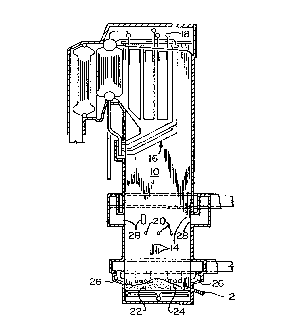
Figure l is a sectional side view of a chemical recovery unit
depicted embodying a segmented smelt spout constructed in accordance with
the present invention;
Figure 2 is a side elevational view of a first embodiment of a
segmented smelt spout illustrated therein as consisting of a base segment and a
plurality of straight segments, constructed in accordance with the present
nvention;
Figure 3 is a side elevational view of the base segment of the first
embodiment of a segmented smelt spout illustrated in Figure 2, constructed in
accordance with the present invention;
Figure 4 is a plan view of the base segment of the first
embodiment of a segmented smelt spout illustrated in Figure 2, constructed in
accordance with the present invention;
1 5 Figure S is a partial sectional view of the base segment of the first
embodiment of a segrnented s~nelt spout illustrated in Figure 2, constructed in
accordance with the present invention, taken substantially along the line 5-5 inFigure 4;
Figure 6 is a side elevational view of one of the plurality of
straight segments of the first embodiment of a segmented smelt spout illustratedin Figure 2, constructed in accordance with the present invention;
Figure 7 is a plan view of one of the plurality of straight segments
of the first embodiment of a segmented smelt spout illustrated in Figure 2,
constructed in accordance with the present invention;
Figure 8 is a partial sectional view of one of the plurality of
straight segments of the first embodiment of a segmented smelt spout illustratedin Figure 2, constructed in accordance with the present invention, taken
substantially along the line 8-8 in Figure 7;
C960990
2 1 p34 4 3
Figure 9 is a side elevational view of a second embodiment of a
segmented smelt spout illustrated therein as consisting of a base segment and a
curved segment and a plurality o~ straight segments, constructed in accordance
with the present invention;
Figure 10 is a side elevational view of the curved segment of the
second embodiment of a segmented smelt spout illustrated in Figure 9,
constructed in accordance with the present invention;
Figure 11 is a plan view of the curved segment of the second
embodiment of a segmented smelt spout illustrated in Figure 9, constructed in
accordance with the present invention; and
Figure 12 is a partial sectional view ofthe curved segment ofthe
second embodiment of a segmented smelt spout illustrated in Figure 9,
constructed in accordance with the present invention, taken substantially along
the line 12-12 in Figure 11.
DESCRIPTION OF THE PREFERRED EMBODIMENT
Referring now to the drawing, and more particularly to Figure 1
thereof, there is depicted therein a chemical recovery unit, generally designated
by reference numeral 10. Inasmuch as the nature of the construction and the
mode of operation of chemical recovery units per se are well-known to those
skilled in the art, it is not deemed necessary, therefore, to set forth herein adetailed description ofthe chemical recovery unit 10 illustrated in Figure 1.
Rather, for purposes of obtaining an understanding of a chemical recovery unit
10, which is suitable for having installed therein a segmented smelt spout
constructed in accordance with the present invention, be it the first embodimentthereofthat is designated by the reference numeral 12 in Figure 2 ofthe
drawing or the second embodiment thereof that is designated by the reference
numeral 12' in Figure 9 of the drawing, and when so installed in the chemical
C960990
21 90443
- 14-
-
recovery unit 10 is operative for the purpose of effecting therewith the
discharge from the chemical recovery unit 10 of smelt, which is composed of
non-burnable materials and which is produced during the course of the
operation of the chemical recovery unit 10, it is deemed to be sufficient that
5 there be presented herein merely a description of the nature of the componentsofthe chemical recovery unit 10 with which the aforereferenced segmented
smelt spout, be it the segmented smelt spout 12 or the segmented smelt spout
12', cooperates. For purposes of the description that follows herein of the
chemical recovery unit 10, it should be noted that the chemical recovery unit 101 O as illustrated in Figure 1 of the drawing is depicted with the segmented smelt
spout 12 installed therein. One may have reference to the prior art, e.g., U.S.
Patent No. 3,304,920, which issued February 21, 1967 to E. C. Chapman, for a
more detailed description of the nature of the construction and the mode of
operation of the components of the chemical recovery unit 10, which are not
1 5 described herein.
Referring furthe~ to Figure 1 of the drawmg, the chemical
recovery unit 10 as illustrated therein includes walls that are lined with steamgenerating tubes, the latter being denoted by the reference numeral 14 in Figure1, which may be in generally tangent relation or may be in closely spaced
20 relation with the space intermediate the tubes 14 being bridged by a fin. Thetubes 14 form part ofthe heat exchange surface ofthe chemical recovery unit
10 with there being additional heat exchange surface identified generally as 16
in the upper region of the chemical recovery unit 10. The tubes 14 carry a
mixture of steam and water at saturation temperature for the particular pressure25 at which the chemical recovery unit 10 is operated with this mixture passing
upwardly through these tubes 12. The chemical recovery unit 10, which is
illustrated in Figure 1 of the drawing, is designed to be operative to produce
- steam at 950 pounds per square inch pressure with this steam being conveyed
C960990
2 1 ~0443
from the header, denoted by the reference numeral 18 in Figure 1, to a desired
point of use and with this steam being superheated to a desired value such as
900 degrees F.
Continuing with the description of the chemical recovery unit 10,
5 which is illustrated in Figure 1 of the drawing, residual liquor obtained from the
Kraft pulping process is introduced into the chemical recovery unit 10 through
the nozzles, denoted by the reference numeral 20 in Figure 1. The residual
liquor thus sprayed into the chemical recovery unit 10 descends downwardly
toward the bottom, denoted by the reference numeral 22 in Figure 1, of the
1 O chemical recovery unit 10 and in doing so passes through an upwardly rising
stream of combustion gases such that a majority of the moisture in the residual
liquor is immediately evaporated with the solid particles falling downwardly
through this rising combustion gas stream and forming a pile, denoted by the
reference numeral 24 in Figure 1, on the hearth or bottom 22 of the chemical
1 5 recovery unit 10. A portion of the burnables, which the aforementioned
residual liquor embodies, are consumed during this descent through the
chemical recovery unit 10 with additional burnables, which the aforementioned
residual liquor embodies, being consumed on the pile 24 and with the non-
burnable materials, which the aforementioned residual liquor embodies, being
20 smelted and periodically withdrawn from the chemical recovery unit 10 through the segmented smelt spout 12 constructed in accordance with the present
invention and to which further reference will be had hereinafter.
Completing for purposes of the instant application the description
of the chemical recovery unit 10, which is illustrated in Figure 1 of the drawing,
25 combustion supporting air is introduced into the chemical recovery unit 10 attwo locations. The primary air is introduced through nozzles, denoted by the
reference numeral 26 in Figure 1, that are spaced relatively close to the bottom22 as, for example, three feet above the bottom 22 of the chemical recovery unit
C960990
21 90443
- 16-
10, while the secondary air is introduced through the nozzles or ports, denoted
by the reference numeral 28 in Figure 1, that are located above the nozzles 20
through which the residual liquor is introduced into the chemical recovery unit
10.
With the preceding by way of background, reference will now be
had for purposes ofthe first embodiment of segmented smelt spout 12
particularly to Figures 2 through 8 of the drawing and for purposes of the
second embodiment of segmented smelt spout 12' particularly to Figures 9
through 12 and 3 through 8, for purposes of describing the segmented smelt
spouts 12 and 12' constructed in accordance with the present invention, which
are designed so as to be installable in a chemical recovery unit 10, which is
illustrated in Figure 1 of the drawing and to which reference has been had
hereinabove. More specifically, the segmented smelt spouts 12 and 12' are
designed so as to be installable in a chemical recovery unit such as the chemical
recovery unit 10 of Figure 1 ofthe drawing so that when so installed therein thesegmented smelt spouts 12 and 12' are operative for the purpose of effecting
therewith the discharge from the chemical recovery unit 10 o'f smelt, which is
composed of non-burnable materials and which is produced during the course
ofthe operation ofthe chemical recovery unit 10.
As best understood with reference to Figures 2 through 8 of the
drawing, the first embodiment of segmented smelt spout 12 comprises an
assembly of segments of different shapes. To this end, the first embodiment of
segmented smelt spout 12 comprises an assembly of segments that includes a
base segment, denoted generally in Figure 2 of the drawing by the reference
numeral 30, that will be described hereinafter with reference to Figures 3, 4 and
5 of the drawing in greater detail, and a plurality of straight segments, each
denoted generally for ease of reference in Figure 2 of the drawing by the same
reference numeral 32, that will be described hereinafter with reference to
C960990
219~7~', 3
Figures 6, 7 and 8 of the drawing in greater detail. In addition to the base
segment 30 and the plurality of straight segments 32 to which reference has
been had above, the first embodiment of segmented smelt spout 12 also
includes a tensioning means, denoted generally in Figure 2 of the drawing by
5 the reference numeral 34, to which further reference will be had hereinafter.
However, suffice it to say for now that the tensioning means 34 is operative forthe purpose of holding the plurality of straight segrnents 32 and the base
segment 30 together while at the same time perrnitting the plurality of straightsegments 32 and the base segrnent 30 to expand and contract thermally.
Continuing with the description of the first embodiment of
segmented smelt spout 12 that is depicted in Figure 2 of the drawing, a
description will next be had herein of the base segment 30 thereof. For
- purposes of this description of the base segment 30 reference will be had in
particular to Figures 3 through 5 of the drawing. As best understood with
15 reference to Figure 5 ofthe drawing, the base segment 30 embodies a
substantially U-shaped configuration. To this end, the base segrnent 30
embodies a pair of upstanding leg portions, each such upstanding leg portion
being denoted for ease of reference by the same reference numeral 36 in the
drawing, and a trough-like portion, denoted in the drawing by the reference
20 numeral 3 8, of varying thickness. In accord with the best mode embodiment ofthe invention, the base segment 30 is formed as an integral member, i.e., the
upstanding leg portions are formed integral with the trough-like portion 38. Fora purpose that will be described herein subsequently, each of the upstanding legportions 36, as can be seen with reference in particular to Figure 4 of the
25 drawing, terrnin~tes at one longitlldin~lly extending end thereof in a lug, each
such lug being denoted for ease of reference by the reference numeral 40 in the
drawing. Each of the upstanding leg portions 36 at the longit~ in~lly extending
end thereof is further provided in adjoining relation to the respective one of the
C960990
21 90443
- 18-
lugs 40, which is located thereat, with a mating, i.e., complementary, surface,
each such mating surface being denoted for ease of reference by the same
reference numeral 42 in the drawing, for a purpose that will be described hereinsubsequently. More specifically, in accord with the best mode embodiment of
5 the invention each such mating surface, as will be best understood with
reference to Figures 3 and 4 of the drawing, preferably comprises a notch,
which is suitably dimensioned so as to be operative as a mating surface, that isforrned in each of the upstanding leg portions 36 at the same longitl1flin~11y
extending end thereof as that whereat a lug 40 is provided.
Completing herein the description of thé base segment 30, the
base segrnent 30 is operative for purposes of effecting therewith the mounting
of a segmented smelt spout, constructed in accordance with the present
invention, in installed relation relative thereto in one of the walls of a chemical
recovery unit, such as the chemical recovery unit 10 illustrated in Figure 1
15 wherein the segmented smelt spout 12 is depicted mounted in installed relation
relative thereto in the chemical recovery unit 10. For purposes of effecting
such mounting of a segmented smelt spout, constructed in accordance with the
present invention, in accordance with the best mode embodiment of the
invention a mounting means, such as that illustrated schematically in Figures 2
20 and 3 of the drawing, wherein the mounting means is denoted generally by the
reference numeral 44, is preferably cooperatively associated with the base
segment 30. The mounting means 44 may take the form of any conventional
type of mounting means that is suitable for use for the purpose of effecting
therewith the mounting of the base segment 30 and thereby concomitantly
25 therewith a segmented smelt spout, constructed in accordance with the presentinvention, in installed relation relative thereto in a chemical recovery unit.
With further reference to the segmented smelt spout 12, next
there will be set forth herein a description of the plurality of straight segrnents
C960990
2 1 90443
- 19-
32 thereof. Since each of the plurality of straight segments 32 is identical both
insofar as the nature of the construction and the mode of operation thereof is
concerned, it is deemed to be sufficient to set forth hereinafter a description of
only one such straight segment 32. Reference will be had in particular to
5 Figures 6, 7 and 8 of the drawing in connection with the description hereinafter
of one such straight segment 32.
To this end, as best understood with reference to Figure 8 of the
drawing, each of the plurality of straight segrnents 32 embodies a pair of
longitudin~lly extending upstanding leg portions, each such longit~ldinAlly
1 O extending upstanding leg portion being denoted for ease of reference by the
same reference numeral 46 in the drawing, and a longitlldin~lly extending
trough-like portion, denoted in the drawing by the reference numeral 48, of
varying thickness. In accord with the best mode embodiment of the invention,
each of the plurality of straight segments 32 is formed as an integral member,
1 5 i.e., the longitl1~1in:~l1y extending upstanding leg portions 46 of each of the
plurality of straight segments 32 are formed integral with the longit--(lin;lllyextending trough-like portion 48 thereo~ For a purpose that will be described
herein subsequently, each of the longit~l-lin~lly extending upstanding leg
portions 46 of each of the plurality of straight segments 32, as will be best
20 understood with reference to Figure 7 of the drawing, is provided with a
protuberance, each such protuberance being denoted for ease of reference by
the same reference numeral 50 in the drawing, formed integrally therewith so as
to project outwardly therefrom and so as to extend for the full length thereof.
Each of the longitlldin~lly extending upstanding leg portions 46 of each of the
25 plurality of straight segments 32 is further provided at each end thereof in
adjoining relation to the protuberance 50 thereof that extends longit l(lin~lly the
full length of each of the longit~ldin~lly extending upstanding leg portion 46 of
each of the plurality of straight segments 42 with a mating surface. More
C960990
2 1 93443
- 20 -
specifically, in accord with the best mode embodiment of the invention one
such mating surface at one end of each of the longit~l~in~lly extending
upstanding leg portions 46 of each of the plurality of straight segments 32, as
will be best understood with reference to Figures 6 and 7 of the drawing,
5 preferably comprises a notch, each such notch for ease of reference being
denoted by the same reference numeral 52 in the drawing, which is suitably
dimensioned so as to be operative as a mating surface in the manner described
hereinafter. Whereas the other such mating surface at the other end of each of
the longitll(lin~l Iy extending upstanding leg portions 46 of each of the plurality
1 O of straight segments 32, in accord with the best mode embodiment of the
invention and as will be best understood with reference to Figures 6 and 7 of
the drawing, preferably comprises a projection, each such projection for ease ofreference being denoted by the same reference numeral 54 in the drawing,
which is suitably dimensioned so as to be operative as a mating surface in the
1 5 manner described hereina~er. Namely, the notches 52 and the projections 54 of
each of the plurality of straight segments 32 are suitably dimensioned so that
when a pair of straight segments 32 are positioned in abutting engagement one
with another so that the pair of straight segments 32 bear an assembled relationone to the other, the projections 54 of one of the pair of straight segments 32
20 are received in the notches 52 of the other of the pair of straight segments 32 in
order to thereby effect therewiLh an interconnection between the pair of straight
segments 32. Similarly, the projections 54 of each of the plurality of straight
segments 32 are suitably dimensioned so that when a straight segment 32 is
positioned in abutting engagement with the base segment 30 so that the straight
25 segment 32 and the base segment 30 bear an assembled relation one to the
other, the projections 54 of the straight segment 32 are received in the notches42 of the base segment 30 in order to thereby effect therewith an
interconnection between the straight segment 32 and the base segment 30. To
C960990
- - -
21 90443
- 21 -
thus summarize, the notches 42 of the base segment 30 as well as the notches
52 and the projections 54 of the straight segment 32 are each suitably
dimensioned so that the projections 54 of each of the straight segments 32 are
complementary to the notches 42 of the base segment 30 as well as to the
5 notches of any other straight segment 32.
Continuing with the description of the segmented smelt spout 12,
constructed in accordance with the present invention and as illustrated in Figure
2 of the drawing, there will now be set forth herein a description of the
tensioning means 34 thereof. For this purpose, reference will be had in
1 O particular to Figure 2 of the drawing. Thus, as best understood with reference
to Figure 2 of the drawing, the tensioning means 34, in accord with the best
mode embodiment of the invention, preferably comprises a pair of tension
cables, only one of which is visible in Figure 2 of the drawing wherein the
tension cable that is visible in Figure 2 is denoted therein by the reference
1 5 numeral 56. Each of the tension cables 56 is designed so as to be both
expandable and contractible for a purpose that will be discussed more fully
hereinafter, and as such are each formed of a conventional type of material thatis suitable for use for the purpose of enabling the tension cable 56 to function in
the aforedescribed manner, i.e., to expand and contract. Although not depicted
20 in the drawing in the interest of m~int~ining clarity of illustration therein, it is
to be understood that each of the tension cables 56 at one end thereof is
preferably provided with a protruding portion, i.e., head, (not shown). This
protruding portion, i.e., head, (not shown) of each of the tension cables 56 is
suitably dimensioned so as to be capable of being received with a sliding fit in a
25 countersunk hole, denoted in Figures 2 and 3 ofthe drawing by the reference
numeral 58, which is provided in each of the lugs 40 of the base segment 30 for
this purpose, i.e., to receive therewithin the protruding portion, i.e., head, (not
shown) of a tension cable 56. The other end of each of the tension cables 56 is
C960990
2 1 90~43
- 22 -
suitably designed so as to be capable of having positioned thereon in secured
relation thereto a suitable fastening member, such as the fastening member
denoted by the reference numeral 60 in Figure 2. Any conventional type of
fastening member suitable for use for the purpose of effecting therewith the
5 securing in place of a tension cable 56 relative to the base segment 30 and the
plurality of straight segments 32 may be utilized as the fastening member 60 forthe tension cable 56.
The function of the tensioning means 34, as has been previously
alluded to herein, is to hold the base segment 30 and the plurality of straight
1 O segrnents 32 of the segmented smelt spout 12 together in assembled relation
such that as best understood with reference to Figure 2 of the drawing the
mating surfaces thereof are maintained in contact with one another while at the
same time permitting the base segment 30 and the individual ones of the
plurality of straight segments 32 ofthe segmented smelt spout 12 to expand and
1 5 contract thermally relative to each other. Namely, as best understood with
reference to Figure 2 ofthe drawing, when the segmented smelt spout 12 is in
its assembled condition, the base segment 30 and the plurality of straight
segments 32 thereof are secured in abutting engagement with one another by
means of the tensioning means 34. To this end, each of the tension cables 56 of
20 the tensioning means 34 is positioned in a longitll(lin~lly extending openingsuitably provided for this purpose in each of the lugs 40 of the base segment 30as well as in a longitlldin~1ly extending opening that is suitably provided for
this purpose in each ofthe longit~l(lin~lly extending upstanding leg portions 46of each of the plurality of straight segments 32 such that the protruding portion,
25 i.e., head, (not shown) provided at one end of each of the tension cables 56 is
received in a respective one of the countersunk holes 58 with which each of the
lugs 40 of the base segment 30 is suitably provided, and with the fastening
member 60 being positioned on the other end of each of the tension cables 56
C960990
21 ~0443
so as to be operative to effect herewith the securing of each of the tension cables
56 in place and thereby concomitantly maintaining in assembled relation one to
another the base segment 30 and the plurality of straight segments 32, which
collectively comprise the segmented smelt spout 12.
Depending upon the relative coefficients of thermal expansion of the
tension cables 58 and the spout segments 30, 32, it is conceivable that differential
expansion between the tension cables and the spout segments could result in
excessive tensile forces arising in the cables. For example since they are directly
contacted by the smelt, the segments of the spout could become much hotter than
10 the tension cables, and unless compensated for, excessive forces could arise
which, since they are in addition to the pre-tension load of the cables 56 could
exceed the working limit of the cables. To avoid this, the cables 56 incorporate a
compensating device (not shown) in the form of a spring arrangement which is
designed to yield resiliently so as to absorb overload tensile forces induced by
differential thermal expansion forces, and thus protect the tensile cables 56 and
their mountings from damage. Various spring devices can be used for this
purpose, for example one or more belleville spring washers (not shown) positioned
between the head at the outer end of the tension cable and the end of the
outermost segment of the spout. Whatever spring device is used for this purpose,
20 it will be designed to accommodate a sufficient compression movement as to
absorb forces resulting from differential expansion of the components, while
maintaining the preset minimum tensile force required to hold the spout segments
together under all operating conditions.
There will now be set forth herein a description of the second
- 23 -
752 1 6-7
2 1 904~3
embodiment of segmented smelt spout 12' illustrated in Figure 9 of the drawing.
As best understood with reference to Figure 9 of the drawing, the segmented
smelt spout 12' like the segmented smelt spout 12, which is illustrated in Figure 2
of the drawing, comprises an assembly of segments of different shapes. More
specifically, like the segmented smelt spout 12, the segmented smelt spout 12'
also includes a base segment 30, a plurality of straight segments 32, a tensioning
means 34 and has a mounting means 44 cooperatively associated therewith.
However, unlike the segmented smelt spout 12, the segmented smelt spout 12' in
addition includes also a curved segment, which is denoted in Figure 9 of the
10 drawing by the reference numeral 61.
Inasmuch as the base segment 30, the plurality of straight segments
32, the tensioning means 34 and the mounting means 44 of the segmented smelt
spout 12' are identical to the base segment 30, the plurality of straight segments
32, the tensioning means 34 and the mounting means 44, respectively, of the
segmented smelt spout 12 insofar as the nature of the construction thereof and
the mode of operation thereof are concerned, it is not deemed necessary in
connection with setting forth herein a description of the segmented smelt spout
12', constructed in accordance with the present invention, to again set forth herein
either a description of the base segment 30 or a description of the plurality of
20 straight segments 32 or a description of the function that the tensioning means 34
performs relative to the base segment 30 and the plurality of straight segments 32
or a description of the mounting means
- 23a -
75216-7
2 1 934 43
- 24 -
44. As such, for purposes of obtaining an understanding of the nature of the
construction and the mode of operation of the segmented smelt spout 12', it is
deemed to be only necessary to set forth hereinafter a description of the natureof the construction and the mode of operation of the curved segment 61, and a
5 description of the function that the tensioning means 34 performs relative to the
curved segment 61.
There will now be set forth herein a description of the curved
segment 61. For this purpose, reference will be had in particular to Figures 10,11 and 12 of the drawing. Thus, as best understood with reference to Figures
1 O 10 and 12 of the drawing~ the curved segrnent embodiés a pair of curved,
longihltlin~lly extending upstanding leg portions, each such curved,
longitllclin~lly extending upstanding leg portion being denoted for ease of
reference by the same reference numeral 62 in the drawing, and a longit~lllin~lly
extending trough-like portion, denoted in the drawing by the reference numeral
1 5 64, of varying thickness. In accord with the best mode embodiment of the
invention, the curved segment.61 is formed as an integral member, i.e., the
curved, longit~1-1in~11y extending upstanding leg portions 62 of the curved
segment 6 l are formed integral with the longihl-lin~lly extending trough-like
portion 64 thereof. For a purpose that will be described herein subsequently,
20 each of the curved, longitu-lin~lly extending upstanding leg portions 62 of the
curved segment 61, as will be best understood with reference to Figure l l of
the drawing, is provided with a protuberance, each such protuberance being
denoted for ease of reference by the same reference numeral 70 in the drawing,
formed integrally therewith so as to project outwardly therefrom and so as to
25 extend for the full length thereof. Each of the curved, longit~l(lin~lly extending
upstanding leg portions 62 of the curved segment 6 l is further provided with a
mating surface at each end thereof in adjoining relation to the protuberance 70
C960990
21 90443
thereof that extends longitll~lin~lly the full length of each of the curved,
longitll(lin~lly extending upstanding leg portions 62 of the curved segment 61.
Continuing, in accord with the best mode embodiment of the
invention one such mating surface at one end of each of the curved,
5 longitll-lin~lly extending leg portions 62 of the curved segment 61, as will be
best understood with reference to Figures 10 and 11 of the drawing, preferably
comprises a notch, each such notch for ease of reference being denoted by the
same reference numeral 72 in the drawing, which is suitably dimensioned so as
to be operative as a mating surface in the manner described hereinafter.
1 O Whereas the other such mating surface at the other end of each of the curved,
longitl1tlin~lly extending upstanding leg portions 62 ofthe curved segment 61,
in accord with the best mode embodiment of the invention and as will be best
understood with reference to Figures 10 and 11 of the drawing, preferably
comprises a projection, each such projection for ease of reference being
1 5 denoted by the same reference numeral 74 in the drawing, which is suitably
dimensioned so as to be operative as a mating surface in the manner described
hereinafter. Namely, the notches 72 and the projections 74 of the curved
segment 61 are suitably dimensioned so that when the curved segment 61 and a
straight segrnent 32 are positioned in abutting engagement one with another so
20 that the curved segment 61 and the straight segment 32 bear an assembled
relation one to another, the projections 54 of the straight segment 32 are
received in the notches 72 of the curved segment 61 in order to effect therewithan interconnection between the curved segment 61 and the straight segment 32.
Similarly, the projections 74 ofthe curved segment 61 are suitably dimensioned
25 so that when the curved segment 61 is positioned in abutting engagement with
the base segment 30 so that the curved segment 61 and the base segment 30
bear an assembled relation one to the other, the projections 74 of the curved
segment 61 are received in the notches 42 of the base segment 30 in order to
C960990
21 90443
- 26 -
thereby effect therewith an interconnection between the curved segment 61 and
the base segment 30. To thus summarize, the notches 42 of the base segment
30 and the notches 52 and the projections 54 of the straight segments 32 as wellas the notches 72 and the projections 74 of the curved segment 61 are each
5 suitably dimensioned so that the projections 54 of the straight segments 32 aswell as the projections 74 of the curved segment 61 are complementary to the
notches 42 of the base segment 30, the notches 52 of a straight segment 32 as
well as the notches 72 of the curved segment 61.
For purposes of completing the description of the segmented
1 O smelt spout 12', which is illustrated in Figure 9 of the drawing, reference will
once again be had herein to the tensioning means 34. The tensioning means 34,
as has been set forth herein previously includes a pair of tension cables 56, only
one of which is visible in Figure 9 of the drawing. Each of the tension cables
56 also as has been set forth herein previously is provided with a protruding
1 5 portion, i.e., head (not shown). This protruding portion, i.e., head, (not shown)
of each of the tension cables 5~ is suitably dimensioned so as to be capable of
being received with a sliding fit in the countersunk hole 58, which is provided
in each ofthe lugs 40 ofthe base segment 30 for this purpose. The other end of
each of the tension cables 56 is suitably designed so as to be capable of having20 positioned thereon in secured relation thereto a suitable fastening member 60.
As has been alluded to herein previously, the function of the
tensioning means 34 is to hold the base segment 30, the curved segment 61 and
the plurality of straight segments 32 of the segmented smelt spout 12' together
in assembled relation such that as best understood with reference to Figure 9 of25 the drawing the mating surfaces thereof are m~int~ined in contact with one
another while at the same time permitting the base segment 30, the curved
segment 61 and individual ones of the plurality of straight segments 32 of the
segmented smelt spout 12' to expand and contract thermally relative to each
C960990
2 1 904 43
- 27 -
other. To this end, each of the tension cables 56 of the tensioning means 34 is
positioned in a longit~lclin~lly extending opening suitably provided for this
purpose in each ofthe lugs 40 ofthe base segment 30 and in a longitll(lin~lly
extending opening that is suitably provided for this purpose in each of the
5 curved, longitl~tlin~lly extending upstanding leg portions 70 of the curved
segment 61 and in a longihl~lin~lly extending opening that is suitably provided
for this purpose in each of the longitudinally extending upstanding leg portions46 of each of the plurality of straight segments 32. With the tension cables 56
so positioned relative to the base segment 30, the curved segment 61 and the
10 plurality of straight segments 32, the protruding portion, i.e., head, (not shown)
provided at one end of each of the tension cables 56 is received in a respectiveone ofthe countersunk holes 58 with which each ofthe lugs 40 ofthe base
segment 30 is suitably provided and the fastening member 60 is positioned on
the other end of each of the tension cables 56 so as to be operative to effect
1 5 therewith the securing of each of the tension cables 56 in place and thereby concomitantly maintaining in assembled relation one to another the base
segment 30, the curved segment 61 and the plurality of straight segments 32,
which collectively comprise the segmented smelt spout 12'.
In accord with the best mode embodiment of the segmented smelt
20 spout, constructed in accordance with the present invention, the base segment30, the curved segment 61 and the individual ones of the plurality of straight
segments 32 preferably each comprise castings each consisting of a
nickel/chrome alloy that is suitable for use for such a purpose, whereby the
respective upstanding leg portions and the respective trough-like portion
25 thereof are formed integrally with each other. Moreover, in accord with the
best mode embodiment of the segmented smelt spout, constructed in
accordance with the present invention, although the base segment 30 is
described hereinabove and is illustrated in the drawing as being provided with
C960990
2'1. 9D~443
- 2~ -
mating surfaces that consist of a pair of notches 42, it is to be understood that
the base segment 30 without departing from the essence of the present
invention could be provided with mating surfaces that consist of only one notch
42 and with the other notch 42 thereof being replaced with a projection similar
in configuration and in dimensions to the projections 54 of the straight
segments 32 and the projections 74 of the curved segment 61. Furthermore, if
the base segment 30 were to be provided with mating surfaces consisting of one
notch 42 and one projection, then each of the plurality of straight segments 32
without departing from the essence of the present invention could be provided
1 O with mating surfaces wherein rather than having both notches 52 thereof being
provided at the same end thereof and both projections 54 thereof being
provided at the same end thereof would be provided at each end thereof with
one notch 52 and one projection 54. Likewise, if the base segment 30 were to
be provided with mating surfaces consisting of one notch 42 and one
1 5 projection, then the curved segment 61 without departing from the essence of
the present invention could be.provided with mating surfaces wherein rather
than having both notches 72 thereof being provided at the same end thereof and
both projections 74 thereof being provided at the same end thereof would be
provided at each end thereof with one notch 72 and one projection 74.
From the preceding description thereof and the illustration thereof
in the drawing, it should now be readily apparent that the segmented smelt
spout, constructed in accordance with the present invention, comprises an
assembly of cast segments of different shapes, which can be used in different
combinations to obtain varying smelt spout angles and varying smelt spout
lengths. In this regard, by way of example and not limitation, the segmented
smelt spout constructed in accordance with the present invention, for example,
may be comprised of a base segment 30 and four individual straight segments
32 so as to extend at a f1rst preestablished angle relative to the horizontal and
C960990
2 1 ~ 3
- 29 -
for a first preestablished length, as does the segmented smelt spout 12, which is
illustrated in Figure 2 of the drawing of the instant application. On the other
hand, the segmented smelt spout constructed in accordance with the present
invention, for example, may be comprised of a base segment 30, a curved
5 segment 61 and three individual straight segments 32 so as to extend at a
second preestablished angle relative to the horizontal and for a second
preestablished length, as does the segmented smelt spout 12', which is
illustrated in Figure 9 of the drawing of the instant application. Therefore, insummary, it should thus be apparent that the length of the segmented smelt
10 spout constructed in accordance with the present invention, generally speaking,
is established by the number of individual straight segments 32 that a particular
segmented smelt spout, constructed in accordance with the present invention,
embodies. Whereas, the angle at which the segmented smelt spout, constructed
in accordance with the present invention, extends relative to the horizontal,
1 5 generally speaking, is established by the number of curved segments 61 that a
particular segmented smelt spo,ut, constructed in accordance with the present
invention, embodies.
Thus, in accordance with the present invention there has been
provided a new and improved smelt spout suitable for use to effect therewith
20 the delivery of smelt from a chemical recovery unit. Moreover, there has beenprovided in accord with the present invention such a new and improved smelt
spout that is characterized in that the smelt spout is non-cooled so as to thereby
obviate any potential safety hazard that might be occasioned by virtue of the
smelt coming into contact with a cooling medium, such as water that might be
25 being used to effect therewith the cooling of the smelt spout. Besides, in
accordance with the present invention there has been provided such a new and
improved smelt spout that is characterized in that the nature of the construction,
which the smelt spout possesses, provides for flexibility insofar as the selection
C960990
21Q0~43
- 30 -
of the spout angle is concerned. As well, there has been provided in accord
with the present invention such a new and improved smelt spout that is
characterized in that the nature of the construction, which the smelt spout
possesses, provides for flexibility insofar as the selection of the length of the
5 smelt spout is concerned. Further, in accordance with the present invention
there has been provided such a new and improved smelt spout that is
characterized in that the nature of the construction, which the smelt spout
possesses, provides for the smelt spout to be composed of relatively small
pieces in order to thereby facilitate the handling thereof during installation of
10 the smelt spout in a chemical recovery unit. Furthermore, there has been
provided in accord with the present invention such a new and improved smelt
spout that is characterized in that the nature of the construction, which the smelt
spout possesses, provides for selective replacement of portions of the smelt
spout, such as those, for example which are subjected to the highest wear,
15 without necessitating that the entire smelt spout be replaced in order to effect
the replacement of such portions of the smelt spout. Also, in accordance with
the present invention there has been provided such a new and improved smelt
spout that is characterized in that the nature of the construction, which the smelt
spout possesses, provides for the smelt spout to be composed of a plurality of
20 segments, each being relatively short in length for the purpose of being able to
better handle the thermal gradients, which are experienced particularly between
the inner and outer surfaces of the thickest portions of the smelt spout that are
in contact with the smelt flow. Additionally, there has been provided in accord
with the present invention such a new and improved smelt spout that is
25 characterized in that the nature ofthe construction, which the smelt spout
possesses, is such that the smelt spout is suitable for incorporation as part of a
new chemical recovery unit. Penultimately, in accordance with the present
invention there has been provided such a new and improved smelt spout that is
C960990
21 90~3
characterized in that the nature of the construction, which the smelt spout
possesses, is such that the smelt spout is suitable for retrofitting into existing
chemical recovery units while at the same time still being suitable for
incorporation as part of a new chemical recovery unit. Finally, there has been
5 provided in accord with the present invention such a new and improved smelt
spout that is characterized in that the nature of the construction, which the smelt
spout possesses, is such that the smelt spout is easy to employ, is reliable in
operation, but which is relatively inexpensive to provide.
While several embodiments of our invention have been shown, it
10 will be appreciated that modifications thereof, some of which have been alluded
to hereinabove, may still be readily made thereto by those skilled in the art.
We, therefore, intend by the appended claims to cover the modifications
alluded to herein as well as all the other modifications which fall within the true
spirit and scope of our invention.
C960990