Note : Les descriptions sont présentées dans la langue officielle dans laquelle elles ont été soumises.
wog~2149 2 1 ~ 0 PCI`/CA95100291
PROC~SS FOR BU~JING OF SULE~R
FIELD OF TI~E INVENTION
This invention relates to the burning o~ elemental
5 sulfur in air to form sulfur dioxide as a stage in the
production of sulfuric acid and other sulfur oxide acids
(referred to hereinafter for convenience merely as sul~uric
acid) .
REVIEW OF THE ART
The conv~nt;on~l proce6s for manufacturing sulfuric
acid comprises burning F-] Lal sul~ur in air to produce
sulfur dioxide, catalytically oxygenating the sulfur
dioxide to produce sulfur trioxide, and absorbing the
sulfur trioxide in water to form sulfuric acid. The
present invention is c r~~ ~A solely with the initial
stage of burning ~l~ Lal sulfur.
The state of the art in conv~nticn~l sulfur combustion
t~--hn;qn~ is described at pages 6 to 17 of a ~Lu~l
"Sulphur Tlsln~l in~r sulphur Combustiorl, Sulphuric Acid'l
describing ;nter alia the terhnolo~y offered by Lurgi for
the burning of liguid sulfur. The sul1'ur is liquified, and
supplied at a ~airly closely controlled te~L ~ LUL ~ in the
range of about 130 - 145C to a rotary atomizer of a form
illu L .1~ ed in the ~LU~lIUL_. The sulfur may either be
burned with some excess of air, or alternatively, as
indicated in the 1,- u~].~u~ with less than a stoirh; ~ LL ic
amount of air, prior to the gases being passed through a
waste heat boiler. If less than a st~irhi~ L ic amount of
air has been uti 1 i 7~1, an after burner will be provided
f ollowing the waste heat boiler in order to complete the
combuStion proces5.A~ nn5 ~f~ g ~,iro~
~ hh~ls~s~ d~clDs~ ;r~ Gi8-R-~5~93q ,,~ (JS~ 3q3~,27s,
Regardless of wh~ther an excess or a deficit of air is
ut; l; ~e~, the combustion process prior to the waste heat
boiler tends in practi.ce to be ; n l~te, with the result
AMENI:~ED SHEET
., . _ : . _ _ _
Wo 95132149 2 1 9 ~ ~ 4 0 PCT/CA95/00291
that liquid sulfLr is deposited on the waste heat boiler
~LLU~LUL~ and the base of the combustion chamber, where it
burns with detrimental effects particularly upon boiler
structures. As will be appreciated, the amount of liguid
5 sulfur passed thro~gh. a burner in such a plant may be very
large, for examplet(60 gallons) per minute, and in practice
atomization of the sulfur typically can result in an
average particle size in excess of 500 microns. This of
course implies the presence of c~nqi~lPrably larger
lO particles within the combustion chamber volume, and in
these cil.;u~-Lanc~s~ it is impossible to ensure sufficient
rapid vaporizatiol1 of the liquid sulfur particles to ensure
complete combustion; some deposition of unburned sulfur
outside the intended combustion zone is inevitable.
A further ~ ~nRi~oration in sulfur burning is to
prevent production of nitrogen oxides due to reaction of
nitrogen and oxygen in the combustion air. The ~LeSe.. e Or
such oxides can ~; qcolour the resulting sulfuric acid, and
20 render it unsuitable for applications outside the
fertilizer industry. The ~Lt:Se~ of excess air in the
combustion chamber, ` ln~od with high combustion
..LuL~, ten~s to promote the formation of nitrogen
oxides; thus it may be adva~La~t.".s as ~L~.~osed in the
25 ~L O~ UL e to utilize _ L less air than is required to
produce lete combustion in the combustion chamber,
since theoretical].y nitrogen oxides will not be formed when
less than a stoi Ch; ~ ' iC amount of air is present.
Combustion can t~1en be completed at lower t, c~LuL._.s
30 ~r.,,~LL~alu of the boiler. In practice, such an approach is
not wholly effective when the admixture of the air and
sulfur fails to provide completely uniform combustion
conditions, while the incomplete combustion of the sulrur
tends to ayyL~Yi~t.e the problem of damage to the plant
35 resulting from the deposition of unburned sulfur and its
subse~uent combustion on surfaces oE the plant structure.
C ~5~,` AMEND~ S~-Er
21 9Q~640
Wo 95/3214g PCT/CA9~100291
6tudies of tlle combustion of sulfur were carried out
in Poland some twenty years ago: reference may be made to
"Studies On Atomizing Liquid Sulfur Using Atomizers Of
Different Construction", Banczyk and Jarzynowski,
International Chemical Engineering, January 1976, pages 74-
78; "M~ ~rni ~tion Of The Installation For The Combustion
Of Liquid Sulfur In Sulfuric Acid Plants", Chwalibog &
Plaskura, Inz. Apar, Chem. 1974, 13t5), pages ~-10; and
"Utilization Of The Studies On Gas Turbulence For The
Construction Of N~w Furnaces For The Combustion Of Liquid
5ulfur", Banczyk & Jurzynowski, Inz. Apar. Chem., 1974,
13 (5), pages 11-14.
SUNNARY OF THE INVENTION
It is an obj,ect of the present invention to address
the above problems, which are o~ very long standing, and to
provide for more satisfactory and complete combustion of
liquid sulfur when burning sulfur in a sulfuric acid plant.
In order to uv~:~ ~ the problems ~icol-ccid above, I
atomize the sulfur through a nozzle providing atomization
to an average particle size of the order of 10 microns,
into a vortex formed in a combustor by a substantially
stoichiometric quantity of combustion air, the vortex being
directed toward6 a reaction chamber. To ensure complete
combustion and ~ cate for any marginally imperfect
proportioning of air and sulfur, a very slight excess of
air may be present, but this should be as small as possible
30 as to reduce nitrogen oxide formation to a minimum. The
very fine atomization of the sulfur `-in~d with the
discharge of the atomized sulfur into an air vortex ensures
extended retention of the sulfur in ~he combustor and very
complete vaporization and combustion of the sulfur in the
~UL or its immediate vicinity. Such complete
combustion in a restricted zone eliminates the undesired
deposition of unbllrned sulfur, and the exposure of the
combustion chamber structure to flame t~ ~ ctu~eS~ thus
... , .,, , ,, ., . ., _ . . , _, _, , ... . . , , . ,, . . , .. ,, , ,, . _ _ _ _ _ _ _ _
WO g~,32l49 2 ~ 9 ~ ~ 4 ~ PCT/CAg~l002gl
prolonging the life both of the waste heat boiler utilized
to cool the gases, and of the reaction chamber itself.
SHORT L~r;::is~l~LlON OF THE DRAWINGS
5 In the drawings:
Figure 1 is an i ~ LL ic partially broken away view of
a burner l~t; l i 7-~1 in; l Ling the invention in a plant
as 8hown in Figure 1;
Figure 2 i5 an end view of the burner;
Figure 3 is a longitudinal elevation of a burner gun
as l~ti l; 7e-l in t3le burner, partially broken away to show
internal a LL Ul_ LUL e:; and
Figure 4 is a section through a nozzle of the burner
gun, on an enlarged scale.
IJES~ .l OF THE ~:;r r;~L~ 3~ 1 M ~ ~ L
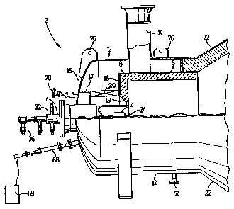
Figure 1 shows diz~L tically a burner 2 attached to
the ~ nn or reaction chamber 22 of a sulfur burning
plant. The burne.r 2, through which enter liquid sulfur and
air, i8 located at one end of the generally cylindrical
refractory lined reaction chamber 22 from the opposite end
of which hot gases exit through z water tube waste heat
boiler for further proc~ ;n~. These gases essentially
Consist of sulfur dioxide and nitrogen. To give ,an idea of
nnc:~ a plant with the capac~ hor burningl~5g tons)
of 8ulfur per day (yielding aboutL~!205 tons)5per d~ of
8ulfuric acidl might have a reaction chamberL~8 feet) in
~ an3i~2 ~eet) long, a bu~,nesr ,,"~ o feet) in
~1;; with a _ Lv~ 6 about~0~inrpe~ in external
rl;~ and an ,~ ;7;n~ gun somel(6 inc` es~ in diameter,
apart from its mounting flange.
The burner 2 i8 a dev~ of the burner described
in Briti8h Patenl: specification No. 1,341,861, which was
originaily developed f or the high rate combustion of
1IYdLV~;aLLV~I fuel8, and is marketed by Conamara Limited
AMEND~ t,
3 ~ IPEAJcP _
2 1 9~6~3
Wo 95/32149 PCT/CA95/00291
under the trade mark AF('f)~F:'r'RTC. The atomizing gun 4,
which is utilized and illustrated in more detail in Figures
3 and 4, is a development of the design disclosed in U. S .
Patent No. 4,72~3,036 (Bennett et al.). Although this
5 patent discloses a nozzle assembly designed for the
h:~n~ll in~ of coal slurries, it has been found that it is
capable of provi ding very f ine atomization in burners
h;-nr~l in~ very large quantities of liquid fuel. A
difficulty which tends to arise in high volume atomizers is
10 that the very high velocities attained at the nozzle give
rise to sonic effects which reduce t~ruuu,ll,uuL and interfere
with the atomization process. This gun has been found
capable both of h;~n~l inq high rates of liquid flow and
producing exceptionally fine atomization without its
15 performance being compromised by sonic effects, and without
requiring very high liquid ~Le~uLes.
The burner :2 shown in Figures 1 and 2 replaces a
burner similar to that shown in the article discussed above
20 in a sulfuric acid plant. The present burner consists of
a combustor formed by a combustor housing 6 lined with
refractory material 8 and concentrically mounted within a
cylindrical windbox 12 ~uLLuullding and ~Yt~ntlinq behind the
combustor so that combustion air entering the windbox 12
25 through a duct 14 passes between a rear wall 16 closing the
rear end of the windbox 12 and a ~LLUULUL~ 17 projecting
from rear wall 16 ) and a plate 18 closing the rear end of
the combustor housing 6, and t_rough a cu.lc~l-LLic
frustor~nic~l opening 19 through ~he rear wall of the
30 combustor housing 6 and the refractory material 8, thus
causing air from the windbox to ,UllV~Lyt: in a vortical flow
on a nozzle 24 at the outcr end of ~he gun 4. A vortical
motion is imparted to this air by a ring of volute blades
20 extending between the structure 17 and plate 18. The
35 presence of these blades results in the air passing through
the gap and the :Erustoc~ni f~ 1 opening being accelerated
into an intense vortex which entrains the atomized sulfur
_ _ _ _ , _ , . . . _ . . . _ . . . _ . _ . . . _ _ _ . _ .
WO95/32149 2 ~ 9~0 PCI/CA95/00291
, --
from the atomizer 4 and vaporizes and burns it during its
retention in a vortical combustion zone within and
extending f orwardly of the combustor such that combustion
will be essentially complete within a distance usually no
more than one combustor diameter in front of the burner
assembly. The :7LLU~_LULe producing the vortical air flow
should be cu~ LLu-:Led so as to avoid ~c ~ and standing
wave ef f ects in the air f low under normal operating
conditions. The rate of flow of combustion air throu~h the
duct 14 is adjutited relative to the sulrur flow rate
through the gun s~lch as to provide enough oxygen to ensure
:~uL_L~ Lially stoichi~ ic combustion of the sulfur,
Lu~Liate ~ n~e being made for at~ i7in~ air utilized
in the gun itself. This at~-i7ing air will typically
amount to about 2% - 4~6 of the total air flow through the
burner. In order to r';nt:'l;n optimum atomization, the
,ILuL-~ o~ the lic~uid 5ulfur s~lrPl;Pcl to the gun 4 is
maintained in the range Or about 130 - 145 C., in which
temperature range the viscosity of sul~ur is sirilar or
lower than that of a number 2 fuel oil; the viscosity of
liquid sulfur ri ses , ~-LL~ ~y rapidly at I _ r~LuL~s
approaching 160C, and 1Q~S rapidly at t - C-LUL~8 below
130C. It is important therefore ~hat the t~ ,ILuL~ of
the sulfur does not rise to approaching 160C prior to
atomization. Typically sulfur and at~ ;7;n~ air ,t)Ll~:S'^UL~_.
of aboutl~OOP~sslc~ will provide at~ 7~t;nn to an average
particle size of 10 micron5 or less for a li~uid of the
viscosity of li~uid sulfur in the above t~ CILUL~: range.
For a plant of the capacity o~ltl; nr~ above, the lic~uid
sulfur flow might typically be~62660 p90und~ per hour aJt~ld~5~4
psig) and 140C, in which ca7e1t,theb air~5low rec~uired for
stoich;c ic burning would be/Q~8990 cublc feet~per minute
atl~t~lnches water ~LeS~UL'3~ at the burner. About.~L5
lbs.J/minute of atomizing air at~l(100 psi~would be required.
Conveniently the atomizing air is preheated to the same
t rl~ULt: as t:he sul~ur, and/or the sulfur and air
p~e~ ec o~ atomizer gun are jacketed with steam or other
AM--N~
C A~
_ _ _ _ _ . _ . _ _ , . _ . , ... . _ . . _ _ _ . _ _ _ _ _ _ _ _ _ _ _ _ _ _ _ _ _ _ _
WO9S/32149 2 1 9~640 YCr/cAg5l00291
7
heated ~luid so as to maintain the desired sul~ur
t~ atuL~ through the gun.
For a ~ A; ~ description of a gun of the type
5 pref erably utilized, ref erence may be made to U . S . Patent
No. 4,728,036. In brief, and referring to Figures 3 and 4,
the gun comprises a cylindrical casing 26, within which are
~U~ LLiC tubes 28 and 30 for conveying air and sulfur
respectively to the nozzle 24 which is secured to the
lO casing 26 and tubes 28 and 30. A space between the casing
26 and the tube 28 is supplied with steam at about 140C
through inlet and out~et connections 32 and 34. Liquid
sulfur is 5~rrlied atl~O p.s.i.~ to the tube 30 through
connectir,n 36, and at ; 7in~ air at the same ~ S ~ur
15 trough cu....ecLion 38 to the tube 28.
The sulfur passes through a central a~_L UL 40 in a
nozzle ba~e 42, amd the d~ in~ air through a ring of
~eL LUL e.B 44 in the base. An atomizer cone member 4 6 is
20 screwed into a th~readed bore in the base 42, and the
sulfur passes from the aP_L Lu,~a 40 through bores 50 and 52
in the cone member 4 6 to an annular chamber def ined
between a cylindri~:al wall 54 projec~ing forwardly from the
base and a~n outside surface of the cone member.
25 Air from the ~ IP~:L ~ 44 passes between the outside of
cylindrical ~ _ 54 and the inside surface of a cap 56
screwed onto an nxtD--n ~1 thread on the base 42 . The cap
defines a LLuD~ J~;r~l internal surface 58 spaced from a
L Us~o~ r~ n:~l surface of the cone member 46 to
30 form a narrow annular divergent frustocnnir~l passage 62.
An outer end of th~ cylindrical wall 54 is also spaced from
the cone member 46 to form a continuation of the passage
62, and from the cap 56 to form a tapering annular passage
64 which enters the passage 62 through an annular external
35 opening and thus causes air to be directed in a ~ u~ yt llL
annular flow onto a~ layer of sulfur flowed over the surface
of the cone member in the passage 62. THe width of the
O
_ . . .. _ _ .. _ _ _ _ _ _ _ _ _ _ _ _ _ _ _ _ _ _ _ _ _ _ _
WO95132149 2 1 9 0 6 4 0 PCT1CA95100291
. --
pAcRaq~-c can be a~justed by means of shims between the cone
member and the base and the cap and the base. Typically
the passage 62 ]laS a width of about~ Z0 . 05ti~ inches, the
passage 64 has a minimum width of aboutf(0.04a) inches, the
5 entrance from the chamber 53 to the passage 62 has a width
of aboutL~0 . 015) inches , and the diameter of the annular
opening ~rom the passage 64 into the passage 62 is aboutl9 ^~
L3 5 incheE~. The outer end of the nozzle 24 is chamfered at
66 50 that the exit from the passage 62 is substantially
l0 perpendicular to the nozzle surfacs.
In order to start up the burner, an A-1~; 1; ArY
removable or retractable gas f ired burner gun 68 is
provided ( see Figures l and 2 ), equipped with an electrical
5 igniter 69. The gun is used to warm up the reaction
chamber prior to use and then to ignite the sulfur, and to
reignite the sulfur in the event th~t combustion is
extinguished for any reason. ConvPnti t~nAl sight ports 70
and an ii-~LL1 ~atiOn port 72 are also provided. A drain
20 74 is provided for any water c~nA~nein~ from combustion air
admitted to the burner, and lirting eyes 76 facilitate
removal and installation of the burner.
In use, the gun 68 is utilized to preheat the
25 combustor and the reaction chamber, following which the
flow of air through the duct 14 and of at~ ; ~; n7 air and
sulfur through th,e gun 4 is started. The burner has a good
LULI~ ~A ratio, i.e. it can operate sat;~fact~rily at much
lower rates of delivery of combustion air and sulfur than
30 its maximum ratin1g, so it can be brought smoothly up to its
rated capacity. The total air supplied is typically 100%
to 102~ of that required to provide the oxygen for
stoich;~ t ic reaction. The slight excess is primarily
;nt--nA~ to allo~ for difficulties in r-;nt~in;n~ precise
35 flow rates, just sufficient to ensure that enough air is
present to provide suf f icient oxyg~n to wholly oxidize the
sulfur to sulfur dioxide. The excess of air should be kept
2 1 9~0
Wo 95132149 PCrtCA95100291
to a minimum so as to avoid generation of nitrogen oxides.
While the atomizing gun described is capable of
providing average sulfur particle sizes of 10 microns or
5 less, the actual average particle size is not believed
particularly critical provided that the average particle is
very much smaller than the average particle size of 500
microns which may occur in existing plants. Accllm; n~ the
avA;l;~h;l;ty of suitable atomizing guns capable of h~nrll;n~
10 the quantity of liquid sulfur required in such a plant, any
average particle size within the same decimal order of
magnitude, logarithm;c~l ly centred on 10 microns, is
believed to be suitable to enable combustion of the sulfur
to be completed during retention in the vortex. The nozzle
15 ~LLu~LuLe of the atomizing gun described is believed
particularly adva--Lc.uuu,ls because of its ability to provide
very fine atomization of large quantities of liquid, whilst
retention in the vortical combustion zone ensures an
adequate ~c,LLullity for vaporization and combustion of the
20 liquid sulfur particles before they can leave this zone.