Note : Les descriptions sont présentées dans la langue officielle dans laquelle elles ont été soumises.
2? ~0~68
SEI-N 96-24
TITLE OF THE INVENTION
OPTICAL CONNECTOR
BACKGROUND OF THE INVENTION
Field of the Invention
The present invention relates to a configuration
of an optical connector for connecting an optical
filter having a waveguide structure to optical elements
such as an optical fiber, a semiconductor device, or
the like.
Related Backctround Art
In an inspection system for an optical line using
an inspection apparatus such as an apparatus with
Optical Time Domain Reflectometry method (OTDR
apparatus), an optical filter for reflecting inspection
light with a predetermined wavelength is generally
disposed in the optical line. This optical filter has
a light-blocking function for cutting off the
inspection light so as to prevent it from being
transmitted to a subscriber's house and a light-
reflecting function for reflecting the inspection light
propagated through the optical line so as to send it
back to the inspection apparatus, thereby inspecting
whether there are fault points in the optical line or
not and detecting light transmission characteristics of
~ the optical line.
As the optical filter applied to the inspection
1
2190r ~8
SEI-N 96-24
system for optical lines, particularly preferable is an
optical filter with a waveguide structure in which a
region having an optical filter function (referred to
as "filter region" hereinafter) is disposed at a core
of an optical waveguide (including optical fiber, thin-
film waveguide, and the like). For example, when a
filter region is formed at a_predetermined portion of a
communication optical fiber used as an optical line, an
optical fiber type optical filter is obtained. Such an
optical filter itself can be used as an optical line.
Accordingly, when a plug is attached to an end of an
optical fiber type optical filter to constitute an
optical connector, its handling is facilitated.
Therefore, when an optical fiber type optical filter is
used to constitute an inspection system for optical
lines, unlike the case where a dielectric multilayer
film filter is used, it is unnecessary for filter parts
to be inserted into the optical line, whereby loss in
signal light can be minimized. Also, an optical filter
formed when a filter region is disposed in a thin-film
waveguide is convenient for various reasons, e.g., it
not only reflects the inspection light but also can
output a branch of the signal light transmitted through
the filter region.
As the filter region of such an optical filter
having a waveguide structure, grating has
2
2? 9068
SEI-N 96-24
conventionally been adopted. Here, "grating " refers to
a region in an optical waveguide where effective
refractive index periodically changes between its
minimum value and maximum value along the optical axis
(longitudinal direction corresponding to a traveling
direction of a signal light in the waveguide). As
disclosed in Japanese Patent.Application Laid-Open No.
62-500052, a grating is formed when silica glass doped
with germanium is irradiated with an interference
pattern of ultraviolet rays. This is based on the fact
that the refractive index of the glass increases
according to a light intensity distribution of the
interference pattern. The grating formed at the core
of the optical waveguide reflects, of the light
advancing through the optical waveguide, a light
component having a narrow wavelength width (referred to
as "reflection wavelength of the grating" hereinafter)
centered at a predetermined wavelength (Bragg
wavelength). This reflection wavelength of the grating
has been known to be determined according to the period
of the grating (grating pitch).
SUMMARY OF THE INVENTION
The inventors have studied the conventional
optical connector including the optical filter from the
viewpoints of performance of the optical filter,
manufacture of the optical filter, and the like. As a
3
-- 21 ~ ~6 ~8
SEI-N 96-24
result, the inventors have concluded that, when an
optical filter having a waveguide structure is utilized
in an inspection system for an optical line, it is
preferable for the grating provided in at least the
core of the optical filter to be accommodated in an
optical connector for optically connecting the
inspection system and the subscriber's terminal to each
other.
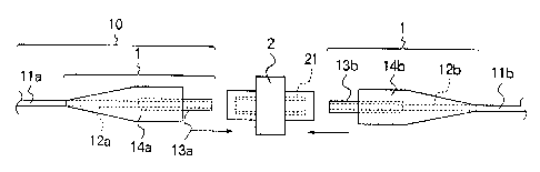
In general, as shown in Fig. 1, for connecting
transmission lines together, an optical connector is
constituted, at least, by plugs 1 attached to tips of
optical fiber cables (optical cords) lla and llb to be
connected together and an alignment sleeve 21 for
optically connecting these plugs 1 together. On the
other hand, as shown in Fig. 3, for connecting a
transmission line and a semiconductor device (e. g.,
light-receiving element) together, an optical connector
constitutes a part of an optical module 20 which
comprises, at least, a ferrule 24 (included in the plug
1) attached to a tip of an optical fiber cable 22, a
sleeve 20a accommodating the ferrule 24, and a holder
20b in which an optical element 20d is mounted on a
main surface of a stem 20c.
Also, the above-mentioned plug is also known as
"cord-attached optical connector" since there are cases
where the plug itself is sold as being attached to a
4
~' ~ ~ ~~~668
SEI-N 96-24
tip of an optical fiber cable, for example.
Accordingly, in this specification, a member
constituted by an optical fiber cord and a plug or
ferrule attached to a tip of the optical fiber cord is
S also simply referred to as "optical connector." Here,
in this specification, "optical fiber cable (optical
cord)" encompasses not only a cord in which the outer
periphery of a single optical fiber is plastic-coated
but also a ribbon type cord in which a plurality of
optical fibers are unitedly plastic-coated (see Fig.
2).
As explained in the foregoing, the optical
connector according to the present invention comprises,
as at least a part of a transmission line, an optical
filter which has a waveguide structure comprised of a
core having a predetermined refractive index and a
cladding having a refractive index lower than that of
the core and covering the outer periphery of the core
and in which a grating for reflecting light of a
predetermined wavelength is disposed at a predetermined
part of the optical filter including the core; a plug
which has a space for accommodating a part of the
optical filter and, while in a state where it
accommodates in the space a tip portion of the optical
~ filter including one end face the optical filter, is
attached to the tip portion. Further, in the optical
5
a ~qc~c~c~g
SEI-N 96-24
connector according to the present invention, in order
to improve the performance of the optical filter or
facilitate the manufacture of the optical connector,
the grating provided in the tip portion of the optical
filter is accommodated in the space of the plug.
As described above, however, in the optical
connector accommodating the .region of the optical
filter where the grating is provided (filter region),
there exists light which, while having a predetermined
wavelength (corresponding to the reflection wavelength
of the grating) to be reflected by the grating, is
radiated from the grating to the cladding region and
passes through the filter region including the grating.
Accordingly, as viewed from the light-emitting end of
the optical filter, it cannot sufficiently exhibit the
filter function for blocking the light to be reflected
by the grating.
Therefore, the optical connector according to the
present invention has a light-blocking structure for
preventing, of the light to be reflected by the
grating, an undesirable light component radiated from
the grating to the cladding and is propagated through
the cladding toward the above-mentioned one end face of
the optical filter from the filter region of the
optical filter, in which the grating is disposed, from
advancing.
6
~~ ~~66~
SEI-N 96-24
In particular, the optical connector according to
the present invention includes the following two
embodiments in terms of position of the grating
accommodated therein.
Namely, in the first embodiment, the plug is
constituted by a ferrule which has a through-hole for
accommodating a part of the optical filter (e. g.,
optical fiber having a grating disposed at a
predetermined position thereof) and, in a state where
lfl at least a part of a tip portion of the optical filter
is accommodated in the through-hole, is attached to
this tip portion; and a flange to which an end of the
ferrule is attached and which has a hollow portion for
accommodating at least a remaining part of the tip
portion of the optical filter which is not accommodated
in the through-hole of the ferrule. In this first
embodiment, the filter region of the optical filter
having the grating is positioned at, of the tip portion
of the optical filter, the remaining part which is not
accommodated in the through-hole of the ferrule but
accommodated in the hollow portion of the flange (see
Fig. 6). In the second embodiment, by contrast, the
filter region of the optical filter having the grating
is positioned at, of the tip portion of the optical
filter, the part accommodated in the through-hole of
the ferrule (see Fig. 18, or the like).
7
2?9066
SEI-N 96-24
In the optical connector according to the present
invention, when a filter region having a grating is
placed so as to extend over the accommodating space of
a ferrule and that of a flange, a sufficient filter
function cannot be obtained. Accordingly, the whole
filter region of the optical filter is accommodated
either in the through-hole of the ferrule or in the
accommodating space of the flange outside of the
ferrule.
As shown in Fig. 6, in the first embodiment, as a
first light-blocking structure, a desired adhesive 243
fills a space defined, in the plug 1, by the outer
peripheral surface of the filter region 122 positioned
at a tip portion 121 {where the coating has been
removed) of the optical filter 12 and the inner wall of
a hollow portion 242 of the flange 24. This adhesive
243 has a refractive index which is substantially the
same as or higher than that of a cladding 124 of the
optical filter 12.
Also, as shown in Fig. 12, in the first
embodiment, in the space defined, in the plug 1, by the
outer peripheral surface of the filter region 122 of
the optical filter 12 and the inner wall of the hollow
portion 242 of the flange 24, a tubular member 250
surrounding the filter region 122 in a state where the
optical filter 12 penetrates therethrough is
8
~'9066~
SEI-N 96-24
accommodated as a second light-blocking structure.
This tubular member 250 has a refractive index which is
substantially the same as or higher than that of the
cladding 124 of the optical filter 12. Preferably, in
this second light-blocking structure, at least a space
defined by the outer peripheral surface of the filter
region 122 of the optical filter 12 and the inner wall
of the tubular member 250 is filled with a desired
adhesive 251. This adhesive 251 has a refractive index
which is substantially the same as or higher than that
of the cladding 124 of the optical filter 12.
Further, as shown in Fig. 14, in the first
embodiment, in the hollow portion-of the plug 1, a
coating 115 surrounding a grating 126 covers at least
the outer peripheral surface of the filter region 122
positioned at the tip of the optical filter 12 as a
third light-blocking structure. In this third light-
blocking structure, the coating 115 has a refractive
index which is substantially the same as or higher than
that of the cladding 124 of the optical filter 12.
Next, in the second embodiment of the present
invention, the light-blocking structure (fourth light-
blocking structure) mentioned above can be realized
when a ferrule 13A is constituted by a light-
~ transmitting material which transmits therethrough
light having a wavelength coinciding with the
9
~ ? 9~~68
SEI-N 96-24
reflection wavelength of the grating i26. This light-
transmitting material has a refractive index which is
substantially the same as or higher than that of the
cladding 124 of the optical filter 12. Fig. i8 shows a
cross-sectional configuration of the optical connector
having the fourth light-blocking structure.
Also, in the second embodiment, the ferrule 13B
may comprise a light-absorbing structure for absorbing
light having a wavelength coinciding with the
reflection wavelength of the grating 126 at a region
where, of the light to be reflected by the grating 126,
a light component radiated from the grating 126 to the
cladding 124_reaches (fifth light-blocking structure).
This fifth light-blocking structure has a configuration
similar to that of Fig. 18, for example, and can be
realized when the ferrule 13B is constituted by a
light-absorbing material which absorbs light having a
wavelength coinciding with the reflection wavelength of
the grating 126. Also, as shown in Fig. 22, the fifth
light-blocking structure can be realized when a light-
absorbing layer 135 made of a material which absorbs
light having a wavelength coinciding with the
reflection wavelength of the grating 126 is formed on
the inner surface of a though-hole 130 of the ferrule
~ i3C.
Further, as a sixth light-blocking structure in
SEI-N 96-24
the second embodiment, as shown in Fig. 24, the outer
diameter of a predetermined portion of a part, in the
tip portion 121 of the optical filter 12c, accommodated
in the through-hole of the ferrule 13 where the light
to be reflected by the grating 126 reaches may be made
smaller than the outer diameter of the rest of the
optical filter 12c. In this.case, a space defined by
the outer peripheral surface of a predetermined portion
of the optical filter 12c and the inner wall of the
through-hole i30 of the ferrule 13 is filled with a
light-absorbing material 136 which absorbs the light
having a wavelength coinciding with the reflection
wavelength of the grating 126. This light-absorbing
material 136 has a refractive index which is
substantially the same as or higher than that of the
cladding 124 of the optical filter 12c.
As shown in Figs. 29 to 34, as a seventh light-
blocking structure in the second embodiment, the plug 1
may have a structure which restricts the light-emitting
opening at one end face 125 of the optical filter 12 to
a size smaller than the size of the cross section of
the optical filter 12 perpendicular to the optical axis
thereof .
Specifically, the seventh light-blocking structure
can be realized when the opening of the through-hole
130 of the ferrule 13 positioned on the above-mentioned
11
'- ~ ? ~~~~8
SEI-N 96-24
one end face side with respect to the filter region 122
having the grating 126 in the tip portion 121 of the
optical filter 12 accommodated in the through-hole 130
of the ferrule 13 is covered with a first light-
s blocking member 140 having an opening with a size
smaller than that of the one end face 125 of the
optical filter 12 (see Fig. 29).
Also, as the seventh light-blocking structure, the
size of a first opening of the through-hole 130 of the
ferrule 13D positioned on the above-mentioned one end
face side with respect to the filter region 122 having
the grating 126 may be made smaller than the size of a
second opening of the through-hole 130 of the ferrule
13D positioned on the side opposite to the first
opening with respect to the filter region 122 by means
of a protrusion 141 disposed at the second opening (see
Fig. 31).
Further, the seventh light-blocking structure may
also be realized when a second light-blocking member
142 having an opening with a size smaller than the
cross-sectional size of the optical filter 12 is
attached to the one end face 125 of the optical filter
12 accommodated in the through-hole 130 of the ferrule
13 (see Fig. 33). This second light-blocking member
142 is accommodated in the through-hole 130 of the
ferrule 13.
12
~ ~~~6~
SEI-N 96-24
Here, each of the above-mentioned configurations
of the seventh light-blocking structure restricts the
diameter of the above-mentioned end face 125 so as to
make it greater than 1.14 times that of the mode field
diameter in the optical filter 12 but smaller than the
outer diameter of the cladding 124 of the optical
filter 12.
As shown in Figs. 35 to 47, as an eighth light-
blocking structure in the second embodiment, the
ferrule 13E or 13F may have a structure for exposing a
region, in the outer peripheral surface of the tip
portion 121 of the optical filter 12 accommodated in
the through-hole 130 of the ferrule 13E or 13F, where,
of the light to be reflected by the grating 126, a
light component radiated from the grating 126 to the
cladding 124 reaches.
Specifically, this eighth light-blocking structure
can be realized when a cutout portion 190 extending
from the outer peripheral surface of the ferrule 13E to
the through-hole 130 accommodating the optical filter
12 or a through-hole (window) 191 which connects. the
outer side face of the ferrule 13F to the inner wall of
the through-hole 130 accommodating the tip portion 121
of the optical filter 12 is provided. Preferably, in
this structure, of the tip portion 121 of the optical
filter 12 accommodated in the through-hole 130 of the
13
SEI-N 96-24
ferrule 13E or 13F, the exposed region is covered with
a refractive-index matching material 700 having a
refractive index which is substantially the same as or
higher than that of the.cladding 124 of the optical
filter 12.
Also, as shown in Fig. 48, as a ninth light-
blocking structure in the second embodiment, the filter
region 122 of the optical filter 12 having the grating
126 positioned in the through-hole 130 of the ferrule
13 may be spaced from the end face 125 of the tip
portion 121 of the optical filter 12 by 3 mm or more.
Next, as shown in Figs. 54 to 57, as a tenth
light-blocking structure in the second embodiment, an
enlarged portion 134a having a cross section greater
than that near an end face 131 of the ferrule 13G may
be disposed on the inner wall of the through-hole 130
of the ferrule 13G. In this configuration, the
enlarged portion 134a is positioned at a region where,
of the light to be reflected by the grating 126, a
light component radiated from the grating 126 to the
cladding 124 reaches. When the tip portion 121 of the
optical filter i2 is accommodated in the through-hole
130 of the ferrule 13G, a gap 135a is formed by the
enlarged portion 134a and the outer peripheral surface
of the optical filter 12.
Also, as shown in Figs. 58 to 70, as an eleventh
14
2?9~6~8
SEI-N 96-24
light-blocking structure in the second embodiment, a
groove may be disposed in a region where, of the light
to be reflected by the grating 126, a light component
radiated from the grating 126 to the cladding 124
reaches, thereby forming a space between the outer
peripheral surface of the optical filter 12 and the
through-hole 130 of the ferrule 13H, 13I or 13J.
In this eleventh light-blocking structure, as in
the case of a groove 135b in Fig. 58, the groove
disposed in the inner wall of the through-hole 130 of
the ferrule 13H may extend along the center axis of the
through-hole 130 from a first end portion of the
ferrule 13H toward a second end portion (including the
end face 131) opposite to the first end portion. Also,
i5 as in the case of a groove 135c in Fig. 62, the groove
disposed in the inner wall of the through-hole 130 of
the ferrule 13I may be formed along the circumferential
direction of a cross section of the through-hole 130
which is perpendicular to the center axis thereof.
Further, as in the case of a groove 135d in Fig. 67,
the groove disposed in the inner wall of the through-
hole 130 of the ferrule 13J may extend spirally with
respect to the center axis of the through-hole 130 from
the first end portion of the ferrule 13J toward the
~ second end portion (including the end face i31)
opposite to the first end portion.
2~ ~i~E~8
SEI-N 96-24
More preferably, in this eleventh light-blocking
structure, a space defined by the outer peripheral
surface of the tip portion 121 of the optical filter 12
and the groove 135b to 135d disposed in the inner wall
of the through-hole 130 is filled with a refractive-
index matching material 800 having a refractive index
which is substantially the same as or higher than that
of the cladding 124 of the optical filter 12. Here, in
the eleventh light-blocking structure, the grooves 135b
to 135d are provided in at least a region of the inner
wall of the through-hole 130 of the ferrule 13H, 13I or
13J which is positioned on the end face side of the tip
portion 121 of the optical filter 12 with respect to
the filter region 122 of the optical filter 12 having
the grating 126, excluding the end portion (including
the end face 131j of the ferrule 13H, 13I or 13J.
The present invention will be more fully
understood from the detailed description given
hereinbelow and the accompanying drawings, which are
given by way of illustration only and are not to be
considered as limiting the present invention.
Further scope of applicability of the present
invention will become apparent from the detailed
description given hereinafter. However, it should be
~ understood that the detailed description and specific
examples, while indicating preferred embodiments of the
16
2~ 90668
SEI-N 96-24
invention, are given by way of illustration only, since
various changes and modifications within the spirit and
scope of the invention will be apparent to those
skilled in the art form this detailed description.
BRIEF DESCRIPTION OF THE DRAWINGS
Fig. 1 is a view showing a first basic
configuration of the optical.connector according to the
present invention for optically connecting optical
fiber cables each including a single optical fiber;
Fig. 2 is a view showing a second basic
configuration of the optical connector according to the
present invention for optically connecting ribbon type
fiber-cables each including a plurality of optical
fibers;
Fig. 3 is a view showing a second basic
configuration of the optical connector according to the
present invention (for optically connecting a
transmission line to an optical element);
Fig. 4 is a view showing a basic assembling step
of the optical connector according to the present
invention;
Fig. 5 is a front view showing a basic
configuration of the optical connector according to the
present invention as a whole;
- Fig. 6 is a view showing a cross-sectional
configuration of the first embodiment r(first light-
17
-- 2 ~ °668
SEI-N 96-24
blocking structure) of the optical connector according
to the present invention, corresponding to the cross
section taken along line A-A of the optical connector
shown in Fig. 5;
Fig. 7 is a view showing an overall cross-
sectional configuration of the optical connector shown
in Fig. 6 at a part indicated by arrow B1,
corresponding to the cross section taken along line B-B
of the optical connector shown in Fig. 5;
Fig. 8 is a view showing a configuration of an
apparatus for an experiment conducted by the inventors;
Figs. 9 and 10 are graphs showing results of the
experiment conducted by use of the apparatus shown in
Fig. 8, representing the relationship between
transmitted light quantity (dBm) and wavelength (nm)
when d is 21 mm and 500 mm, respectively;
Fig. 11 is a view for explaining how, of light to
be reflected by a grating, a light component propagated
through a cladding region behaves;
Fig. 12 is a view showing a cross-sectional
configuration of the first embodiment (second light-
blocking structure) of the optical connector according
to the present invention, corresponding to the cross
section taken along line A-A of the optical connector
~ shown in Fig. 5;
Fig. 13 is a view showing an overall cross-
18
219i~~~~8
SEI-N 96-24
sectional configuration of the optical connector shown
in Fig. 12 at a part indicated by arrow B2,
corresponding to the cross section taken along line B-B
of the optical connector shown in Fig. 5;
Fig. 14 is a view showing a cross-sectional
configuration of the first embodiment (third light-
blocking structure) of the optical connector according
to the present invention, corresponding to the cross
section taken along line A-A of the optical connector
shown in Fig. 5;
Fig. 15 is a view showing an overall cross-
sectional configuration of the optical connector shown
in Fig. 14 at a part indicated by arrow B3,
corresponding to the cross section taken along line B-B
of the optical connector shown in Fig. 5;
Fig. 16 is a view showing a part of an assembling
step for the second embodiment of the optical connector
according to the present invention (fourth light-
blocking structure and first applied example of fifth
light-blocking structure), corresponding to the cross
section taken along line A-A of the optical connector
shown in Fig. 5;
Fig. 17 is a view showing an overall cross
sectional configuration of the optical connector shown
in Fig. 16 at a part indicated by arrow C1,
corresponding to the cross section taken along line C-C
19
2 ~ '~Ob~~
SEI-N 96-24
of the optical connector shown in Fig. 5;
Fig. 18 is a view showing a cross-sectional
configuration of the second embodiment of the optical
connector according to the present invention (fourth
light-blocking structure and first applied example of
fifth light-blocking structure), corresponding to the
cross section taken along line A-A of the optical
connector shown in Fig. 5;
Fig. 19 is a view showing an overall cross-
sectional configuration of the optical connector shown
in Fig. 18 at a part indicated by arrow C2,
corresponding to the cross section taken along line C-C
of the optical connector shown in Fig. S;
Fig. 20 is a view showing a part of an assembling
step for the second embodiment of the optical connector
according to the present invention (second applied
example of fifth light-blocking structure),
corresponding to the cross section taken along line A-A
of the optical connector shown in Fig. 5;
Fig. 21 is a view showing an overall cross-
sectional configuration of the optical connector shown
in Fig. 20 at a part indicated by arrow C3,
corresponding to the cross section taken along line C-C
of the optical connector shown in Fig. 5;
- Fig. 22 is a view showing a cross-sectional
configuration of the second embodiment of the optical
2?9~6~8
SEI-N 96-24
connector according to the present invention (second
applied example of fifth light-blocking structure),
corresponding to the cross section taken along line A-A
of the optical connector shown in Fig. 5;
Fig. 23 is a view showing an overall cross-
sectional configuration of the optical connector shown
in Fig. 22 at a part indicated by arrow C4,
corresponding to the cross section taken along line C-C
of the optical connector shown in Fig. 5;
Fig. 24 is a perspective view showing the form of
a tip portion of an optical filter in the second
embodiment of the optical connector according to the
present invention;
Fig. 25 is a view showing a part of an assembling
step for the second embodiment of the optical connector
according to the present invention (sixth light-
blocking structure), corresponding to the cross section
taken along line A-A of the optical connector shown in
Fig. 5;
Fig. 26 is a view showing a cross-sectional
configuration of the second embodiment of the optical
connector according to the present invention (sixth
light-blocking structure), corresponding to the cross
section taken along line A-A of the optical connector
shown in Fig. 5;
Fig. 27 is a view showing an overall cross-
21
~'~~66~
SEI-N 96-24
sectional configuration of the optical connector shown
in Fig. 26 at a part indicated by arrow C5,
corresponding to the cross section taken along line C-C
of the optical connector shown in Fig. S;
Fig. 28 is a view showing a cross-sectional
configuration of the second embodiment of the optical
connector according to the present invention (an
applied example of sixth light-blocking structure),
corresponding to the cross section taken along line A-A
i0 of the optical connector shown in Fig. 5;
Fig. 29 is a view showing a cross-sectional
configuration of the second embodiment of the optical
connector according to the present invention (first
applied example of seventh light-blocking structure),
corresponding to the cross section taken along line A-A
of the optical connector shown in Fig. 5;
Fig. 30 is a view showing the front face of the
optical connector shown in Fig. 29 as viewed from a
direction indicated by arrow E1, corresponding to the
front face of the optical connector viewed from a
direction indicated by arrow E shown in Fig. 5;
Fig. 3i is a view showing a cross-sectional
configuration of the second embodiment of the optical
connector according to the present invention (second
applied example of seventh light-blocking structure),
corresponding to the cross section taken along line A-A
22
2~ ~06d~
SEI-N 96-24
of the optical connector shown in Fig. 5;
Fig. 32 is a view showing the front face of the
optical connector shown in Fig. 31 as viewed from a
direction indicated by arrow E2, corresponding to the
S front face of the optical connector viewed from a
direction indicated by arrow E shown in Fig. 5;
Fig. 33 is a view showing a cross-sectional
configuration of the second embodiment of the optical
connector according to the present invention (third
i0 applied example of seventh light-blocking structure),
corresponding to the cross section taken along line A-A
of the optical connector shown in Fig. 5;
Fig. 34 is a view showing the front face of the
optical connector shown in Fig. 33 as viewed from a
15 direction indicated by arrow E3, corresponding to the
front face of the optical connector viewed from a
direction indicated by arrow E shown in Fig. 5;
Fig. 35 is a view showing an overall configuration
of a plug (first applied example of eighth light-
20 blocking structure) in the second embodiment of the
optical connector according to the present invention;
Fig. 36 is a view showing a part of an assembling
step for the second embodiment of the optical connector
according to the present invention (first applied
25 example of eighth light-blocking structure),
corresponding to the cross section taken along line F1-
23
2~~~~~8
SEI-N 96-24
F1 of the plug shown in Fig. 35;
Fig. 37 is a view showing a cross-section of a
ferrule shown in Fig. 35 taken along line H1-H1;
Fig. 38 is a view showing a cross-section of the
ferrule shown in Fig. 35 taken along line G1-G1;
Fig. 39 is a view for explaining how light
advances in an optical fiber.;
Fig. 40 is a view showing an overall configuration
(first applied example of eighth light-blocking
structure) in the second embodiment of the optical
connector according to the present invention;
Fig. 41 is a view showing a cross section of the
optical connector shown in Fig. 40 taken along line H2-
H2;
Fig. 42 is a view showing an overall configuration
of the plug (second applied example of eighth example)
in the second embodiment of the optical connector
according to the present invention;
Fig. 43 is a view showing a part of an assembling
step for the second embodiment of the optical connector
according to the present invention (second applied
example of eighth light-blocking structure),
corresponding to the cross section taken along line F2-
F2 of the plug shown in Fig. 42;
Fig. 44 is a view showing a cross-section of the
ferrule shown in Fig. 42 taken along line H3-H3;
24
SEI-N 96-24
Fig. 45 is a view showing a cross-section of the
ferrule shown in Fig. 42 taken along line G2-G2;
Fig. 46 is a view showing an overall configuration
(second applied example of eighth light-blocking
structure) in the second embodiment of the optical
connector according to the present invention;
Fig. 47 is a view showing a cross section of the
optical connector shown in Fig. 46 taken along line H4-
H4;
Fig. 48 is a view showing a cross-sectional
configuration of the second embodiment of the optical
connector according to the present invention (ninth
light-blocking structure), corresponding to the cross
section taken along line A-A of the optical connector
shown in Fig. 5;
Fig. 49 is a view showing the front face of the
optical connector shown in Fig. 48 as viewed from a
direction indicated by arrow E4, corresponding to the
front face of the optical connector viewed from a
direction indicated by arrow E shown in Fig. 5;
Fig. 50 is a view showing a configuration of an
apparatus for measuring the wavelength dependency in
transmissivity of an optical filter to which no
connector is attached (having a grating not covered
~ with a plug);
Fig. 51 is a graph showing a result of measurement
~~~~~~8
SEI-N 96-24
of an optical filter to which no connector is attached,
as measured by means of the apparatus shown in Fig. 50;
Fig. 52 is a view showing a configuration of an
apparatus for measuring the wavelength dependency in
transmissivity of an optical filter to which a
connector is attached (having a grating covered with a
plug);
Fig. 53 is a graph showing a result of measurement
of an optical filter to which a connector is attached,
as measured by means of the apparatus shown in Fig. 52;
Fig. 54 is a view showing a part of an assembling
step for the second embodiment of the optical connector
according to the present invention (tenth light-
blocking structure), corresponding to the cross section
taken along line A-A of optical connector shown in Fig.
5;
Fig. 55 is a view showing an overall cross-
sectional configuration of the optical connector shown
in Fig. 54 at a part indicated by arrow C6,
corresponding to the cross section taken along line C-C
of the optical connector shown in Fig. 5;
Fig. 56 is a view showing a cross-sectional
configuration of the second embodiment of the optical
connector according to the present invention (tenth
' light-blocking structure), corresponding to the cross
section taken along line A-A of the optical connector
26
~~9~~~8
SEI-N 96-24
shown in Fig. 5;
Fig. 57 is a view showing an overall cross-
sectional configuration of the optical connector shown
in Fig. 56 at a part indicated by arrow C7,
corresponding to the cross section taken along line C-C
of the optical connector shown in Fig. 5;
Fig. 58 is a view showing a part of an assembling
step for the second embodiment of the optical connector
according to the present invention (first applied
example of eleventh light-blocking structure),
corresponding to the cross section taken along line A-A
of the optical connector shown in Fig. 5;
Fig. 59 is a view showing an overall cross-
sectional configuration of the optical connector shown
in Fig. 58 at a part indicated by arrow C8,
corresponding to the cross section taken along line C-C
of the optical connector shown in Fig. 5;
Fig. 60 is a view showing a cross-sectional
configuration of the second embodiment of the optical
connector according to the present invention (first
applied example of eleventh light-blocking structure),
corresponding to the cross section taken along line A-A
of the optical connector shown in Fig. 5;
Fig. 61 is a view showing an overall cross-
- sectional configuration of the optical connector shown
in Fig. 60 at a part indicated by arrow C9,
27
Z ~ ~~668
SEI-N 96-24
corresponding to the cross section taken along line C-C
of the optical connector shown in Fig. 5;
Fig. 62 is a view showing a part of an assembling
step for the second embodiment of the optical connector
according to the present invention (second applied
example of eleventh light-blocking structure),
corresponding to the cross section taken along line A-A
of the optical connector shown in Fig. 5;
Fig. 63 is a view showing an overall cross-
sectional configuration of the optical connector shown
in Fig. 62 at a part indicated by arrow C10,
corresponding to the cross section taken along line C-C
of the optical-connector shown in Fig. 5;
Fig. 64 is a view showing a cross-sectional
configuration of the second embodiment of the optical
connector according to the present invention (second
applied example of eleventh light-blocking structure),
corresponding to the cross section taken along line A-A
of the optical connector shown in Fig. 5;
Fig. 65 is a view showing an overall cross-
sectional configuration of the optical connector shown
in Fig. 64 at a part indicated by arrow C11,
corresponding to the cross section taken along line C-C
of the optical connector shown in Fig. 5;
~ Fig. 66 is a view showing a cross-sectional
configuration of the second embodiment of the optical
28
2?9~~68
SEI-N 96-24
connector according to the present invention (second
applied example of eleventh light-blocking structure in
which the groove-forming position is altered),
corresponding to the cross section taken along line A-A
of the optical connector shown in Fig. 5;
Fig. 67 is a view showing a part of an assembling
step for the second embodiment of the optical connector
according to the present invention (third applied
example of eleventh light-blocking structure),
corresponding to the cross section taken along line A-A
of the optical connector shown in Fig. 5;
Fig. 68 is a view showing, with a magnification, a
main part of the ferrule shown in Fig. 67;
Fig. 69 is a view showing a cross-sectional
configuration of the second embodiment of the optical
connector according to the present invention (third
applied example of eleventh light-blocking structure in
which the groove-forming position is altered),
corresponding to the cross section taken along line A-A
of the optical connector shown in Fig. 5; and
Fig. 70 is a view showing a cross-sectional
configuration of the second embodiment of the optical
connector according to the present invention (third
applied example of eleventh light-blocking structure in
which the groove-forming position is altered),
corresponding to the cross section taken along line A-A
29
SEI-N 96-24
of the optical connector shown in Fig. 5.
DESCRIPTION OF THE PREFERRED EMBODIMENTS
In the following, the optical connector according
to the present invention will be explained with
reference to Figs. 1 to 70.
The optical connector according to the present
invention has, at least, a basic configuration shown in
any of Figs. 1 to 3. For example, Fig. 1 shows an
optical connector for optically connecting together
optical fiber cables (optical cords) lla and llb in
which respective single optical fibers 12a and 12b are
coated with plastic. In the optical connector of Fig.
1, a plug 1 is attached to a tip portion (where the
optical fiber i2a is exposed) of one optical fiber
cable 11a. The plug 1 comprises a ferrule 13a attached
to the tip portion of the fiber cable 11a, a flange
holding an end of the ferrule 13a (see Figs. 4 and 5),
and a cover 14a for protecting the ferrule 13a and the
flange. Also, another plug 1 is attached to a tip
portion (where the optical fiber 12b is exposed) of the
other optical fiber cable 11b. This another plug 1
also comprises a ferrule 13b, a flange (see Figs. 4 and
5), and a cover 14b. These optical fiber cables lla
and llb are optically connected to each other by way of
~ an adapter 2 accommodating an alignment sleeve 21. At
this time, a part of each of the ferrules 13a and 13b
SEI-N 96-24
is accommodated in the alignment sleeve 21 in the
adapter 2.
In this specification, "optical fiber cable
(optical cord)" encompasses not only a cord in which a
single optical fiber is plastic-coated but also ribbon
type optical cords 15a and 15b in which a plurality of
optical fibers 16a and 16b are unitedly plastic-coated,
respectively (see Fig. 2). Fig. 2 shows an optical
connector for optically connecting together the optical
fiber cables (optical cords) 15a and 15b which
respectively include a plurality of optical fibers 16a
and 16b. A plug 1 is attached to a tip portion (where
the optical fiber 16a is exposed) of one optical fiber
cable 15a. This plug 1 has a ferrule 17a in which a
guide pin hole 18a is formed along the optical fiber
16a while a guide pin 19a is attached to an end face.
Also, a ferrule 17b (included in a plug) is attached to
a tip portion (where the optical fiber 16b is exposed)
of the other optical fiber cable 15b. In this ferrule
17b, a guide hole 18b is formed along the optical fiber
16b while a guide pin 19b is attached to an end face
thereof. When one guide pin hole 18a and the other
guide pin 19b engage with each other while the other
guide pin hole 18b and one guide pin 19a engage with
each other, the ferrules lea and 17b optically connect
the optical fiber cables 15a and 15b together.
31
~?Q~~~~
SEI-N 96-24
The above-mentioned plug 1 is also referred to as
code-attached optical connector 10 since there are
cases where the plug itself is sold as being attached
to a tip of the optical fiber cable lla or llb (or 15a
or i5b), for example. Accordingly, the optical
connector according to the present invention
encompasses this cord-attached optical connector 10.
Such an optical connector 10 (including the cord-
attached optical connector) enables not only the
optical connection between light-transmitting lines as
shown in Figs. 1 and 2 but also optical connection
between a transmission line and an optical element.
Fig. 3 shows a configurational example in which the
optical connector (code-attached optical connector) is
connected to an optical module 20. Namely, a ferrule
24 (included in the plug 1) attached to a tip portion
(where an optical fiber 23 is exposed) of an optical
fiber cable 11 is accommodated in a sleeve 20a of the
optical module 20. This optical module 20 is
constituted by the sleeve 20a, a stem 20c in which an
optical element 20d such as a light-receiving element
(photo-sensitive device) is mounted on the main surface
thereof, and a holder 20b for holding the optical
element at a predetermined position.
Next, a basic assembling step for the optical
connector according to the present invention will be
32
2~~~~~8
SEI-N 96-24
explained with reference to Fig. 4.
First, prepared is the optical fiber cable 11
(including an optical filter) having a waveguide
structure formed by a core having a predetermined
refractive index and a cladding having a refractive
index lower than that of the core and covering the
core, in which a grating with a refractive index
periodically changing along the longitudinal direction
(along the traveling direction of the light propagating
therethrough) is formed at a predetermined position in
the core. This optical fiber cable is formed as a
coating is applied to the outer peripheral surface of
an optical fiber 12 (referred to as "optical filter"
hereinafter) in which the grating is provided. In
particular, in a typical configuration of the optical
filter 12 in the optical connector according to the
present invention, the coating has been removed from
its tip portion 121, and a region having the grating is
referred to as a filter region 122.
This optical filter 12 successively penetrates
thorough a cover 14 and a flange 24 having a hollow
portion 242 and a holding portion 241 for holding a
ferrule 13, such that the tip portion 121 from which
the coating has been removed is inserted into a
- through-hole 130 of the ferrule 13. Then, in a state
where the ferrule 13 is attached to the tip portion 121
33
~~~~8
SEI-N 96-24
of the optical filter 12, a first end face 131 of the
ferrule 13 is polished so as to coincide with an end
face 125 of the optical filter 12 (see Fig. 6).
Here, the through-hole 130 has an inner diameter
which is substantially the same as the diameter of the
optical filter 12. In this specification,
"substantially the same" refers to a state where the
diameter of the optical filter 12 and the inner
diameter of the through-hole 130 coincide with each
other to such an extent that the optical filter 12 can
be appropriately held.
Then, in a state where a second end face 132 of
the ferrule 13 attached to tie optical filter 12 is
accommodated in the holding portion 241 of the flange
24, the ferrule 13 is fixed to the flange 24.
Accordingly, an optical filter such as that shown in
Fig. 5 is obtained. Here, the overall basic
configuration of the optical connector shown in Fig. 5
is common to optical connectors which will be explained
hereinafter. Accordingly, Fig. 5 will be referred to
in the following explanation of the optical connectors
each time when necessary.
In the following, embodiments of the optical
connector according to the present invention will be
~ explained. Here, the optical connector according to
the present invention encompasses, according to the
34
2~~~~68
sEI-N 96-24
position of the grating accommodated therein, the
following two embodiments.
Namely, the plug attached to the tip portion 121
of the optical filter 12 is constituted by the ferrule
13 which has the through-hole 130 for accommodating a
part of the optical filter 12 (e. g., optical fiber
having a grating disposed at.a predetermined position
in the core) and, while in a state where at least a
part of the tip portion 121 of the optical filter 12 is
accommodated in the through-hole 130, is attached to
this tip portion 121; and the flange 24 having the
holding portion 241 to which an end (including the end
face 132) of the ferrule 13 is attached and which has
the hollow portion 242 for accommodating at least a
part of the tip portion 121 of the optical filter 12
which is not accommodated in the through-hole 130 of
the ferrule 13. In this first embodiment, the filter
region 122 of the optical filter 12 having the grating
126 is positioned at, of the tip portion 121 of the
optical filter 12, a part which is not accommodated in
the through-hole 130 of the ferrule 13 but accommodated
in the hollow portion 242 of the flange 24. In the
second embodiment, by contrast, the filter region 122
of the optical filter 12 having the grating 126 is
~ positioned at, of the tip portion 121 of the optical
filter 12, a part accommodated in the through-hole 130
~ '~Q~6~
SEI-N 96-24
of the ferrule 13.
In the optical connector according to the present
invention, when the filter region 122 having the
grating 126 is placed so as to extend over the
accommodating space of the ferrule 13 and that of the
flange 24, a sufficient filter function cannot be
obtained. In other words, a.stress added to a part of
the filter region 122 which is accommodated in the
ferrule 13 mainly depends on the coefficient of linear
expansion of the ferrule 13, and a stress added to a
remaining part of the filter region 122 which is a
accommodated in the accommodating space of the flange
24 depends on the coefficient of linear expansion of a
covering member such as a coating, a filler (adhesive),
i5 the flange 24 or the like. If the filter region 122 is
covered by members having coefficient of linear
expansions different from each other, the stress
distribution in a longitudinal direction in the filter
region 122 can not be in uniform state. Accordingly,
in order to uniform the stress distribution in the
longitudinal direction in the filter region 122, the
whole filter region 122 of the optical filter 12 is
accommodated either in the through-hole 130 of the
ferrule 13 or in the accommodating space of the flange
24 outside of the ferrule 13.
In particular, the optical connector according to
36
9 ~~b~~
SEI-N 96-24
the present invention has a light-blocking structure
for preventing, of the light to be reflected by the
grating, a light component which has been radiated from
the grating to the cladding so as to be propagated
through the cladding toward the above-mentioned one end
face of the optical filter from the filter region of
the optical. filter, in which. the grating is disposed,
from advancing. In the following, the respective
light-blocking structures will be explained
successively from the first to second embodiments with
reference to Figs. 6 to 70.
In this specification, "waveguide" refers to a
circuit or line for transmitting signal light having a
predetermined wavelength as being confined in a
predetermined region by utilizing a difference in
refractive index between a core and a cladding, which
encompasses optical fiber, thin-film waveguide, and the
like. Further, "tip portion" of the optical filter at
least includes a part of the optical filter which is
accommodated in the plug (constituted by a ferrule only
or a ferrule and a flange).
(First Embodiment)
In the following, a first light-blocking structure
of the optical connector in the first embodiment of
~ the present invention will be explained.
Fig. 6 is a lateral cross-sectional view
37
2 ~ 9J668
SEI-N 96-24
(corresponding to a cross-sectional view taken along
line A-A of Fig. 5) showing a configuration of the
optical connector according to the present invention
having the first light-blocking structure, whereas Fig.
7 is a cross-sectional view (corresponding to a cross-
sectional view taken along line B-B of Fig. 5) of the
optical connector at a portion indicated by arrow B1 of
Fig. 6. This optical connector is constituted by the
optical filter l2 which is obtained when the grating
126 is formed in a single-mode optical fiber having a
core and a cladding 124; the ferrule 13 for
accommodating a tip portion of the optical filter 12 in
the through-hole 130 thereof; and the flange 24 having
the holding portion 241 to which an end of the ferrule
13 is attached.
The optical filter 12 is supposed to be used in an
inspection system for an optical communication network
employing an OTDR apparatus. In an optical line
constituting the optical communication network, signal
light for optical communications is transmitted from a
station to a subscriber's terminal, while inspection
light from the OTDR apparatus is transmitted in order
to inspect the state of the optical line. As the
inspection light, light having a wavelength different
from that of the signal light is used. When this
inspection light enters the subscriber's terminal, it
38
~"~
SEI-N 96-24
unfavorably becomes a noise in the signal light.
Accordingly, it is necessary for an optical filter for
cutting off the inspection light to be disposed in the
optical line. The optical filter 12, which responds to
such necessity, blocks the inspection light as viewed
from the subscriber's terminal side by providing the
grating 126, which reflects light with a predetermined
wavelength, in the core 123 of the optical fiber
constituting a part of the optical line.
14 Though both the core 123 and cladding 124 of the
optical filter 12 are mainly composed of silica glass
{Si02); while the cladding 124 is made of substantially
pure silica glass, silica glass constituting the core
123 is doped with GeO~ which is a material for
15 increasing the refractive index. As a result, the core
123 has a refractive index higher than that of the
cladding 124, thereby forming a relative refractive
index difference of about 0.35 between the core 123
and the cladding 124.
2fl The grating 126 is a region in the core 123 where
its effective refractive index periodically changes
between the minimum refractive index and the maximum
refractive index along the optical axis {longitudinal
direction) of the optical filter 12. In other words,
25 ~ the grating 126 is a region having a refractive index
distribution in which the effective refractive index
39
2~9~~~~
SEI-N 96-24
repeatedly changes between the minimum refractive index
and the maximum refractive index along the optical
axis. This grating 126 reflects, over a relatively
narrow wavelength range centered at a reflection
S wavelength (Bragg wavelength) which is determined by
the period of change in refractive index, i.e., grating
period (also known as grating pitch), light having the
reflection wavelength of the grating 126. This
reflection wavelength of the grating 126 coincides with
the wavelength of the above-mentioned inspection light.
The grating 126 can be formed utilizing a
phenomenon that, when silica glass doped with germanium
is irradiated with ultraviolet rays, the refractive
index at the irradiated portion thereof increases by an
amount corresponding to the intensity of the
ultraviolet rays. Namely, when an interference fringe
of ultraviolet rays is irradiated from the surface of
the cladding 124 toward the core 123 doped with
germanium, a refractive index distribution
corresponding to the light intensity distribution of
the interference fringe is formed in the core at a
region irradiated with the interference fringe. The
region having thus formed refractive index distribution
is the grating 126. In this case, the minimum
~ refractive index at the portion where the grating 126
is formed substantially coincides with the original
2 a ~i~~6~6~
SEI-N 96-24
effective refractive index (effective refractive index
before the ultraviolet irradiation) of the core 123.
Numeral 115 in Fig. 6 refers to a UV-cutoff resin
coating which covers the surface of the cladding 124,
functioning to protect the core 123 and the cladding
124. The resin coating 115 is eliminated at a tip
portion of the optical filter 20 so that the core 123
can be irradiated with ultraviolet rays in order to
form the grating 126 therein as mentioned above.
The ferrule 13 is a tubular member made of
zirconia surrounding the tip portion 121 of the optical
filter 12 from which the resin coating 115 has been
removed. The through-hole 130 of the ferrule 13 has an
inner diameter of 0.126 mm, while its inner surface is
formed as a mirror surface.
The flange 24 is a tubular holding member in which
a rear end portion of the ferrule 13 is attached to the
holding portion 241 thereof. The hollow portion 242 of
the flange 24 has an inner diameter of 1 mm and
accommodates, of the optical filter 12, a part (filter
region 122) including the grating 126. In the hollow
portion 242 of the flange 24, the space between the
optical filter 12 and the flange 24 is filled with an
adhesive 243, by which the optical filter 12 is fixed
~ to the inside of the flange 24. Here, as the adhesive
243, a resin adhesive having a refractive index
41
2?~~~~8
SEI-N 96-24
substantially the same as that of the cladding 124 is
used.
The optical connector according to the present
invention is characterized in that the grating 126 is
positioned in the hollow portion 242 of the flange 24.
As a result, of the light with the reflection
wavelength of the grating 126, a light component
radiated from the grating 126 to the cladding 124 is
reduced, thereby increasing the light-blocking ratio.
First, in the following, explanation will be
provided for a fact that light is radiated toward the
cladding 124 from the grating 126 formed in a glass
region including at least the core 123, thereby
lowering the light-blocking ratio of the optical filter
i5 12. The inventors have confirmed the above-mentioned
fact by conducting an experiment using an apparatus
shown in Fig. 8. This experimental apparatus is used
for investigating a fact that light having the
reflection wavelength of a grating 116 formed in a core
of an optical fiber 100 is radiated from the grating
116 toward a cladding. Here, the optical fiber 100 in
which the grating 116 has been formed is equivalent to
an optical fiber type optical filter. As in the case
of the optical filter 12 in this embodiment, the
optical fiber 100 is a silica glass-based single-mode
fiber whose core is doped with germanium. The grating
42
2 o~6E8
SEI-N 96-24
116 has a length of 10 mm, a predetermined grating
pitch, and a reflection wavelength of about 1,554 nm.
The cladding of the optical fiber 100 is coated with a
resin material except for both end portions thereof.
One end thereof from which the resin coating has been
removed is connected to a super luminescent diode (SLD)
200 by way of a fiber adapter 210. The SLD 200 is a
semiconductor light-emitting device which outputs light
in a predetermined wavelength range including the
reflection wavelength of the grating 116. The other
end from which the resin coating has been removed is
connected to a spectrum analyzer 300 by way of a fiber
adapter 310. The grating 116 is spaced from the end-
face of the spectrum analyzer 300 by a distance d with
a portion of the optical fiber 100 from which the resin
coating has been removed.
The inventors caused the SLD 200 to emit light so
as to make inspection light incident on the optical
fiber 100 and detected, by the spectrum analyzer 300,
spectra of light transmitted through the portion having
the grating 116 for the cases where d was 21 mm (see
Fig. 9j and 500 mm (see Fig. 10), respectively. Figs.
9 and 10 show their corresponding results of detection.
While decrease peaks 400 and 410 in the transmitted
light quantity due to ref lection of light at the
grating 116 appear respectively in Figs. 9 and 10, the
43
2~906~8
sEZ-N 96-24
decrease peak 400 in the case where d = 21 mm is
remarkably smaller than the decrease peak 410 in the
case where d = 500 mm. Namely, the amount of
attenuation in transmission of the light having a
wavelength to be blocked by the grating 116 in the case
where d = 21 mm is smaller than that in the case where
d = 500 mm. Since the grating 116 disposed in the
optical fiber 100 has the same configuration regardless
of whether d = 21 mm or d = 500 mm, the difference in
amount of attenuation in transmission is not caused by
the reflectance of the grating 116 but the difference
in distance from the grating 116 to the spectrum
analyzer 300.
In view of this fact, the above-mentioned
difference in amount of attenuation in transmission is
considered as follows. Since the grating 116 includes
a portion whose refractive index has locally increased,
inconsistency in mode field is generated between the
portion where the grating is formed and the other
portion. When light having the reflection wavelength
of the grating reaches the grating, a part thereof
advances through the grating while being reflected
thereby. Here, due to the above-mentioned
inconsistency in mode .field, light radiated from each
portion of the grating to the cladding is generated.
Fig. 11 is a view for explaining how the light
44
SEI-N 96-24
radiated from the grating 116 to a cladding behaves.
In this drawing, numeral 112 refers to a core of the
optical fiber 100, whereas numeral 114 refers to the
cladding. Also, numeral 120 refers to light radiated
from the grating 116 to the cladding 114. As shown in
Fig. 11, such light advances through a region
comprising the cladding 114 and the core 112 so as to
reach a portion in front of the grating 116. Since the
light-confining effect of the glass region comprising
14 the cladding 114 and the core 112 is weaker than that
in the core 112 alone, the light radiated from the
grating 116 attenuates its power by a relatively large
amount as it advances. Accordingly, as in the case of
the above-mentioned results of the experiment, the
light having the above-mentioned reflection wavelength
detected by the spectrum analyzer 300 becomes less and
the decrease peak in the transmitted light quantity
becomes greater as the distance from the grating 116 to
the spectrum analyzer 300 is greater.
In general, a ferrule of an optical connector is
constituted by a material such as zirconia having a
high light reflectivity, while its inner surface is
formed as a mirror surface. Accordingly, when a tip
portion of the optical fiber 100, which is an optical
~ filter, including the grating 116 is accommodated in
the ferrule, the light radiated from the grating and
-- ~ ~ ~~i~~~8
SEI-N 96-24
then emitted out of the cladding 114 is reflected by
the inner surface of the ferrule so as to return to the
inside of the cladding 114 and advance to a portion in
front of the grating 116, whereby the light-blocking
effect by the optical filter having a waveguide
structure has not always been attained sufficiently.
In view of such a fact,. the optical connector
according to the present invention is provided.
Namely, in the optical connector of Fig. 6, of the
optical fiber type optical filter 12, a part (filter
region 122) including the grating 126 is accommodated
in the hollow portion 242 of the flange 24. Since the
adhesive 243 does not have a reflectivity as high as
that of the ferrule 13, of the light having a
wavelength corresponding to the reflection wavelength
of the grating 126 (light to be reflected by the
grating 126), a light component radiated from the
grating 126 to the cladding 124 advances while leaking
into the adhesive 243 placed around the cladding i24.
Thereafter, while the light radiated from the grating
126 reaches the part of the optical filter 12
accommodated in the through-hole 130 of the ferrule 13,
a component of the light radiated from the grating 126
which has leaked into the adhesive 243 is blocked by
~ the end face 132 of the ferrule 13 and cannot advance
further therefrom. Consequently, of the light having
46
SEI-N 96-24
the reflection wavelength of the grating 126, an
undesirable light component which is radiated to the
cladding 124 and then passes through the grating 126
has a reduced power, whereby the optical connector of
Fig. 6 (first light-blocking structure) can block, of
the light to be reflected by the grating 126, a light
component which has not been. reflected thereby
(referred to as "radiated light" hereinafter).
Further, in the optical connector of Fig. 6, since
the adhesive having a refractive index substantially
the same as that of the cladding 124 fills the space
between the optical filter 12 and the flange 24, the
light radiated from the grating 126 is hardly reflected
by the outer surface of the cladding 124. Accordingly,
the radiated light from the grating 126 extends to the
adhesive 243 quite easily, whereby the radiated light
can be blocked with a very high ratio.
In the following, a second light-blocking
structure of the optical connector in accordance with
the first embodiment will be explained.
Fig. 12 is a lateral cross-sectional view
(corresponding to a cross-sectional view taken along
line A-A of Fig. S) showing a configuration of the
optical connector according to the present invention
~ having the second light-blocking structure. Fig. 13 is
a cross-sectional view (corresponding to a cross-
47
~I ~~~~~
SEI-N 96-24
sectional view taken along line B-B of Fig. 5) of the
optical connector at a portion indicated by arrow B2 of
Fig. 12. In this optical connector, between the tip
portion 121 of the optical filter 12 from which the
coating 115 has been removed and the hollow portion 242
of the flange 24, a tubular member 250 surrounding the
outer peripheral surface of the cladding 124 of the
optical filter 12 is disposed. The tubular member 250
has an inner diameter of 0.14 mm, while the tip portion
121 of the optical filter 12 penetrates through the
tubular member 250. Also, the grating 126 is
positioned within the tubular member 250. Disposed
between the optical filter 12 and the tubular member
250 is an adhesive 251, by which the tubular member 250
is fixed to the outer peripheral surface of the optical
filter 12. The adhesive 251 also intervenes between
the tubular member 250 and the hollow portion 242 of
the flange 24, whereby the tubular member 250 is fixed
onto the inner surface of the hollow portion 242 of the
flange 24. The adhesive 251 has a refractive index
substantially the same as that of the cladding 124 of
the optical filter 12, whereas the tubular member 250
has a refractive index substantially the same as that
of the adhesive 251 and that of the cladding 124.
In the optical connector of Fig. 12, of the light
having the reflection wavelength of the grating 126, a
48
2 ~ 9~~68
SEI-N 96-24
leaking light component radiated from the grating 126
to the cladding 124 advances while leaking into the
adhesive 251 and the tubular member 250. In
particular, in the optical connector of Fig. 12, since
the adhesive 251 and the tubular member 250 have a
refractive index substantially the same as that of the
cladding 124, the light radiated from the grating 126
{leaking light component) extends to the adhesive 251
and the tubular member 250 quite easily. Thereafter,
while the light radiated from the grating 126 reaches
the part of the optical filter 12 accommodated in the
through-hole 130 of the ferrule 13, of the light
radiated from the grating 126, at least a leaking light
component which has been distributed into the adhesive
251 and the tubular member 250 is blocked by the
ferrule 13 and cannot advance further therefrom.
Consequently, of the light having the reflection
wavelength of the grating 126, a light component
radiated to the cladding 124 has a reduced power,
whereby the optical connector of Fig. 12 can block the
light radiated from the grating 126 with a very high
ratio.
Further, in this second light-blocking structure,
since the tubular member 250 is disposed within the
hollow portion 242 instead of filling the whole hollow
portion 242 in the flange 24 with the adhesive 243, the
49
2?9668
SEI-N 96-24
amount of the adhesive becomes smaller than that in the
first light-blocking structure. Accordingly, such a
phenomenon that the adhesive 243 contracts upon curing
so as to impart a stress to the grating 126 and thereby
fluctuate characteristics of the grating 126 is
prevented from occurring. Consequently, the optical
connector of Fig. 12 can securely exhibit a desired
filter function.
In the following, a third light-blocking structure
of the optical connector in accordance with the first
embodiment of the present invention will be explained.
Fig. 14 is a lateral cross-sectional view
(corresponding to a cross-sectional view taken along
line A-A of Fig. 5) showing a configuration of the
optical connector according to the present invention
having the third light-blocking structure. Fig. 15 is
a cross-sectional view (corresponding to a cross-
sectional view taken along line B-B of Fig. 5) of the
optical connector at a portion indicated by arrow B3 of
Fig. i4. The optical connector of Fig. 14 differs from
that of Fig. 6 in the configuration of the optical
filter cable 11 accommodated therein. Namely, in the
optical filter cable 11 in Fig. i2, the UV-cutoff resin
coating 115 is disposed around the filter region 122
- including the grating 126. This optical filter cable
11 is obtained by a method comprising the steps of
SEI-N 96-24
removing the coating 115 from a predetermined part of
an optical fiber; irradiating this part with a
ultraviolet interference fringe to form the grating
126; and then forming the coating 115 at this part
S again. Here, this coating 115 has a refractive index
substantially the same as that of the cladding 124 of
the optical filter 12.
The space between the optical filter 12 and the
hollow portion 242 of the flange 24 in Fig. 14 is
filled with the adhesive 243, by which the optical
filter 12 is fixed to the inside of the hollow portion
242. Here, the adhesive 243 has a refractive index
substantially the same as that of the cladding 124 and
that of the coating 115.
In the optical connector of Fig. 14, of the light
having the reflection wavelength of the grating 126,
the light component radiated from the grating 126 to
the cladding 124 advances while leaking into the
coating 115 and the adhesive 243. In particular, in
the third light-blocking structure, since the coating
115 and the adhesive 243 have a refractive index
substantially the same as that of the cladding 124, the
light radiated from the grating 126 extends to the
coating 115 and the adhesive 243 quite easily.
Thereafter, while the light radiated from the grating
126 reaches the part of the optical filter 12
51
2~9~66~
SEI-N 96-24
accommodated in the through-hole 130 of the ferrule 13,
a leaking light component of the light radiated from
the grating 126 which has been propagated through the
coating 115 and the adhesive 243 is blocked by the
ferrule 13 and cannot advance further therefrom.
Consequently, of the light having the reflection
wavelength of the grating 126, a light component which
is radiated to the cladding 124 has a\reduced power,
whereby the optical connector of Fig. 14 can block the
radiated light with a very high ratio.
Further, in this third light-blocking structure,
unlike the first light-blocking structure, since the
coating.115 is formed around the filter region 122,
influence of the stress imparted to the grating 126
i5 when the adhesive 243 contracts upon curing is reduced,
whereby fluctuation in characteristics of the grating
126 becomes less. Accordingly, the optical connector
of Fig. 14 having the third light-blocking structure
can securely exhibit a desired filter function.
As explained in detail in the foregoing, in the
optical connector in the first embodiment of the
present invention (first to third light-blocking
structures), the light radiated from the grating of the
optical filter advances while leaking into the gap
between the optical filter and the flange and then is
blocked by the end face of the ferrule. Consequently,
52
SEI-N 96-24
unnecessary radiated light from the grating is reduced,
whereby the optical connector in the first embodiment
of the present invention has a high light-blocking
ratio.
(Second Embodiment)
In the following, a fourth light-blocking
structure of the optical connector in the second
embodiment of the present invention will be explained.
Fig. 16 is a lateral cross-sectional view
(corresponding to a cross-sectional view taken along
line A-A of Fig. 5) of each member, showing a part of
an assembling step for the optical connector according
to the present invention having the fourth light-
blocking structure; whereas Fig. 17 is a cross-
sectional view (corresponding to a cross-sectional view
taken along line C-C of Fig. 5) of the optical
connector at a portion indicated by arrow C1 of Fig.
16. This optical connector is used for connecting the
optical fiber type optical filter 12 to another optical
element (e. g., optical fiber or semiconductor device)
and adapted to accommodate the optical filter i2
therein. Specifically, the optical connector is
constituted by the ferrule 13A having the though-hole
130 for accommodating the tip portion 121 of the
optical filter 12 therein and the flange 24 having the
holding portion 241 to which the rear end portion of
53
--
SEI-N 96-24
the ferrule 13A is attached.
Next, with reference to Figs. 16 and 17, the
fourth light-blocking structure of the optical
connector according to the present invention will be
explained. The ferrule 13A is a member for surrounding
and holding the tip portion 121 of the optical filter
12 from which the resin coating 115 has been removed.
In the center of the ferrule 13, the through-hole 130
extends along the center axis of the ferrule 13A. The
tip portion 121 of the optical filter 12 is inserted
into the though-hole 130. The flange 24 is a tubular
holding member in which the rear end portion of the
ferrule 13A is attached to the holding portion 241
thereof. In the hollow portion 242 of the flange 24,
the part of the optical filter 12 covered with the
resin coating 115 is accommodated.
As the fourth light-blocking structure in the
optical connector of Fig. 16, the ferrule 13A is
constituted by a light-transmitting material which
transmits therethrough the light having the reflection
wavelength of the grating 126. Accordingly, when the
optical filter 12 is accommodated in the optical
connector of Fig. 16, of the light having the
reflection wavelength of the grating 126, an
unnecessary radiated light component radiated from the
grating 126 to the cladding 124 is transmitted though
54
SEI-N 96-24
the ferrule 13A so as to be radiated to the outside.
As a result, the light-blocking ratio of the optical
filter 12 is increased. Here, as the above-mentioned
light-transmitting material, various kinds of materials
can be used, though those transmitting the light having
the reflection wavelength of the grating 126 with a
higher ratio is more preferable. As a specific example
of this light-transmitting material, optical glass such
as silica glass is suitable.
In the conventional optical connector, the ferrule
is constituted by a material with a high light
reflectivity such as zirconia, while the inner surface
thereof is formed as a mirror surface. Accordingly, as
can be seen from the experiment explained with
reference to Figs. 8 to 11, when the tip portion of the
optical fiber 100 including the grating 116 is
accommodated in the ferrule, the light radiated from
the grating 116 so as to be emitted out of the cladding
114 is reflected by the inner surface of the ferrule so
as to return to the inside of the cladding 114 and then
advances to a part in front of the grating 116, whereby
the light-blocking effect by the optical filter has not
always been attained sufficiently.
In view of such a fact, the fourth light-blocking
structure of the optical connector according to the
present invention is provided. Namely, when the
~~ ~~~ 68
SEI-N 96-24
optical filter 12 is accommodated in the optical
connector having the fourth light-blocking structure,
of the light having the reflection wavelength of the
grating 126, a light component which is radiated from
the grating 126 to the cladding 124 and then reaches
the outer surface of the cladding 124 so as to be
emitted out of the cladding 124 is transmitted though
the ferrule 13A so as to be radiated therefrom to the
outside. Accordingly, it is hard to generate such a
phenomenon that the leaking light component radiated
from the grating i26 to the cladding 124 is emitted out
of the cladding i24 and then is reflected by the inner
surface of the ferrule 13A so as to return to the
inside of the optical filter 12 and advance to a
portion in front of the grating 126. Consequently, of
the light having the reflection wavelength of the
grating 126, the leaking light component radiated to
the cladding 124 so as to pass through the filter
region 122 has a reduced power, whereby the optical
connector having the fourth light-blocking structure
increases the light-blocking ratio of the optical
filter 12.
Here, in the case where the light-transmitting
material constituting the ferrule 13A has a refractive
index which substantially coincides with that of the
surface layer portion of the cladding 124 of the
56
2 ~ ~~~6~
SEi-N 96-24
optical filter 12, when the optical filter 12 is
accommodated in the optical connector, the light
radiated from the grating 126 is hardly reflected by
the interface between the optical filter 12 and the
S ferrule 13A. Consequently, the light radiated from the
grating 126 is transmitted through the ferrule 13A
quite efficiently, whereby the light-blocking ratio of
the optical filter 12 can be increased very much.
Also, in the case where the he light-transmitting
material constituting the ferrule 13A has a refractive
index higher than that of the surface layer portion of
the cladding 124 of the optical filter 12, when the
optical connector 12 is accommodated in the optical
connector, the light radiated from the grating 126 is
hard to be totally reflected by the interface between
the optical filter 12 and the ferrule 13A.
Consequently, the light radiated from the grating 126
is transmitted through the ferrule 13A efficiently,
whereby the light-blocking ratio of the optical filter
12 can be increased greatly.
Fig. 18 is a lateral cross-sectional view
(corresponding to a cross-sectional view taken along
line A-A of Fig. S) showing the optical connector
obtained by way of the assembling step of Fig. 16.
Fig. 19 is a cross-sectional view (corresponding to a
cross-sectional view taken along line C-C of Fig. 5) of
57
SEI-N 96-24
the optical connector at a portion indicated by arrow
C2 of Fig. 18. The tip portion 121 of the optical
filter 12 from which the resin coating 115 has been
removed is inserted into the through-hole 130 of the
ferrule 13A, while the grating 126 is also accommodated
in the through-hole 130 of the ferrule 13A. In the
hollow portion 242 of the flange 24, the portion of the
optical filter 12 covered with the resin coating 115 is
accommodated. The space between the coating 115 of the
optical filter 12 and the hollow portion 242 of the
flange 24 is filled with an adhesive 255, by which the
optical filter 12 is fixed to the inside of the hollow
portion 242 of the flange 24.
In the optical connector of Fig. 18, of the light
radiated from the grating 126 to the cladding 124 so as
to reach the outer surface of the cladding 124, the
leaking light component radiated to the outside of the
cladding 124 is transmitted through the ferrule 13A so
as to be radiated to the outside. Consequently, of the
light having the reflection wavelength of the grating
126, the unnecessary radiated light component radiated
to the cladding 124 so as to pass through the filter
region 122 has a reduced power. Accordingly, the
optical connector having the fourth light-blocking
structure has a high light-blocking ratio and can also
be favorably used as a constituent for an inspection
58
2~ ~~ ~6~8
SEI-N 96-24
system for optical lines.
As explained in detail in the foregoing, in the
optical connector having the fourth light-blocking
structure, when an optical fiber type optical filter is
accommodated therein, the light radiated from the
grating of the optical filter is transmitted though the
ferrule so as to be radiated to the outside.
Accordingly, the light component passing though the
filter region so as to advance to a portion in front of
the grating is reduced, whereby the light-blocking
ratio of the optical filter can be increased.
In the following, a fifth light-blocking structure
of the optical connector in the second embodiment of
the present invention will be explained.
As the fifth light-blocking structure in the
optical connector according to the present invention,
the ferrule 13B is constituted by a light-absorbing
material which absorbs light having the reflection
wavelength of the grating 126 {first applied example).
Here, since the manufacture and configuration of the
optical connector in the first applied example of the
fifth light-blocking structure are the same as those
(Figs. 16 - 19) explained in the foregoing except for
the ferrule 13, they will not be explained in the
following. In the optical connector in which the first
applied example of the fifth light-blocking structure
59
2~ 9~6~8
SEI-N 96-24
is adopted, of the light having the reflection
wavelength of the grating 126, the unnecessary radiated
light component radiated from the grating 126 to the
cladding 124 is absorbed by the ferrule 13B, whereby
the light-blocking ratio of the optical filter 12 is
increased. Here, as the above-mentioned light-
absorbing material, while various kinds of materials
can be used according to the reflection wavelength of
the grating 126, those absorbing the light having the
reflection wavelength of the grating 126 with a higher
ratio are more preferable. For example, the ferrule
13B may be made of glass doped with praseodymium, which
is a rare earth element, when the reflection wavelength
is at 1.3-~m band; whereas it may be made of glass or
polyimide resin doped with erbium, which is a rare
earth element, when the reflection wavelength is at
1.55-I~m band.
In the conventional optical connector, the ferrule
is constituted by a material with a high light
reflectivity such as zirconia, while the inner surface
thereof is formed as a mirror surface. Accordingly, as
can be seen from the experiment explained with
reference to Figs. 8 to 11, when the tip portion of the
optical fiber 100, which is an optical filter,
including the grating 116 is accommodated in the
ferrule, the light radiated from the grating 116 so as
2?98668
SEI-N 96-24
to be emitted out of the cladding 114 is reflected by
the inner surface of the ferrule so as to return to the
inside of the cladding 114 and then advances to a part
in front of the grating 116, whereby the light-blocking
effect by the optical filter has not always been
attained sufficiently.
In view of such a fact, the optical connector
according to the present invention having the fifth
light-blocking structure (first applied example) is
provided. Namely, when the optical filter 12 is
accommodated in the optical connector having the fifth
light-blocking structure (first applied example), of
the light having the reflection wavelength of the
grating 126, a light component which is radiated from
the grating 126 to the cladding 124 and then reaches
the outer surface of the cladding 124 so as to be
emitted out of the cladding 124 is absorbed by the
ferrule 138. Accordingly, suppressed is such a
phenomenon that the light radiated from the grating 126
to the cladding 124 is emitted out of the cladding 124
and then is reflected by the inner surface of the
through-hole 130 of the ferrule 13B so as to return to
the inside of the optical filter 12 and advance to a
portion in front of the grating 126. Consequently, of
the light having the reflection wavelength of the
grating 126, the unnecessary radiated light component
61
2~ 9068
SEI-N 96-24
which is radiated to the cladding 124 so as to pass
through the filter region 122 has a reduced power,
whereby the optical connector having the fifth light-
blocking structure (first applied example) increases
the light-blocking ratio of the optical filter 12.
Here, in the case where the light-absorbing
material constituting the ferrule 13B has a refractive
index which substantially coincides with that of the
surface layer portion of the cladding 124 of the
optical filter 12 in the fifth light-blocking structure
(first applied example), the light radiated from the
grating 126 is hardly reflected by the interface
between the optical filter 12 and the ferrule 13B.
Consequently, the light radiated from the grating 126
is absorbed by the ferrule 13B quite efficiently,
whereby the light-blocking ratio of the optical filter
12 can be increased very much.
Also, in the case where the light-absorbing
material constituting the ferrule 13B has a refractive
index higher than that of the surface layer portion of
the cladding 124 of the optical filter 12 in the fifth
light-blocking structure (first applied example), the
light radiated from the grating 126 is hard to be
totally reflected by the interface between the optical
filter 12 and the ferrule 138. Consequently, the light
radiated from the grating 126 is absorbed by the
62
2 ~ 90568
SEI-N 96-24
ferrule 13B efficiently, whereby the light-blocking
ratio of the optical filter 12 can be increased
greatly.
The configuration of the optical connector having
the ferrule 13B made of the light-absorbing material as
the fifth light-blocking structure (first applied
example) is the same as that of the optical connector
having the fourth light-blocking structure shown in
Figs. 18 and 19. The tip portion 121 of the optical
filter 12 from which the resin coating 115 has been
removed is inserted into the through-hole 130 of the
ferrule 13B, while the grating 126 is also accommodated
in the through-hole 130 of the ferrule 138. In the
hollow portion 242 of the flange 24, the portion of the
optical filter 12 covered with the resin coating 115 is
accommodated. The space between the coating 115 of the
optical filter 12 and the hollow portion 242 of the
flange 24 is filled with the adhesive 255, by which the
optical filter 12 is fixed to the inside of the hollow
portion 242 of the flange 24.
In the optical connector having the fifth light-
blocking structure (first applied example), of the
light radiated from the grating 126 to the cladding 124
so as to reach the outer surface of the cladding 124,
the light component radiated to the outside of the
cladding 124 is absorbed by the ferrule 138.
63
2 ~ ~~~668
SEI-N 96-24
Consequently, of the light having the reflection
wavelength of the grating 126, the light component
radiated to the cladding 124 so as to pass through the
filter region 122 has a reduced power. Accordingly,
the optical connector having the fifth light-blocking
structure {first applied example) has a high light-
blocking ratio and can also be favorably used as a
constituent for an inspection system for optical lines.
In the following, the fifth light-blocking
structure (second applied example) of the optical
connector in the second embodiment of the present
invention will be explained.
Fig. 20 is a lateral cross-sectional view
(corresponding to a cross-sectional view taken along
line A-A of Fig. 5) of each member, showing a part of
an assembling step for the optical connector according
to the present invention having the fifth light-
blocking structure (second applied example); whereas
Fig. 21 is a cross-sectional view (corresponding to a
cross-sectional view taken along line C-C of Fig. 5) of
the optical connector at a portion indicated by arrow
C3 of Fig. 20. This optical connector is constituted
by the ferrule 13C having the though-hole 130 for
accommodating the tip portion 121 of the optical filter
12 therein, the flange 24 having the holding portion
241 to which the rear end portion of the ferrule 13C is
64
2~ 9~)<68
SEI-N 96-24
attached, and a light-absorbing layer 135 formed on the
inner surface of the through-hole 130 of the ferrule
13C.
While the form of the ferrule 13C is similar to
that of the above-mentioned optical connector of Figs.
16 to 19 (having the fourth light-blocking structure or
fifth light-blocking structure (first applied
example)), the material thereof is different from that
in the optical connector having the structure of the
first applied example. Namely, the material of the
ferrule 13C is conventionally-used zirconia, which is
inappropriate as a light-absorbing material
constituting the above-mentioned ferrule 13B since it
efficiently reflects light of 1.3-~m and 1.55-~m bands
Which are often used as the inspection light wavelength
for optical lines.
In the optical connector having this fifth light-
blocking structure (second applied example), however,
the light-absorbing layer 135 is formed on the inner
surface of the ferrule 13C, which acts like a ferrule
made of a light-absorbing material. This light-
absorbing layer 135 is constituted by a light-absorbing
material which reflects the light having the reflection
wavelength of the grating 126. As mentioned above,
various kinds of materials can be used as the light-
absorbing material according to the reflection
w 219~6E8
SEI-N 96-24
wavelength of the grating 126. Here, since the light-
absorbing layer 135 is formed on the inner wall of the
through-hole 130, it is shaped like a pipe. The tip
portion 121 of the optical filter 12 from which the
coating 115 has been removed is inserted into the
through-hole defined by the light-absorbing layer 135
as shown in Fig. 22.
When the optical filter 12 is accommodated in the
optical connector having the fifth light-blocking
structure (second applied example), of the light having
the reflection wavelength of the grating 126, a light
component which is radiated from the grating 126 to the
cladding 124 and then reaches the outer surface of the
cladding 124 so as to be emitted out of the cladding
124 is absorbed by the light-absorbing layer 135.
Accordingly, suppressed is such a phenomenon that the
light radiated from the grating 126 to the cladding 124
is emitted out of the cladding 124 and then returns to
the inside of the optical filter 12 so as to advance to
a portion in front of the grating 126. Consequently,
of the light having the reflection wavelength of the
grating 126, the unnecessary radiated light component
which is radiated to the cladding 124 so as to pass
through the filter region 122 has a reduced power,
whereby the optical connector of Fig. 22, as in the
case of the optical connector having the fifth light-
66
2?9Q668
SEI-N 96-24
blocking structure (first applied example), can
increase the light-blocking ratio of the optical filter
12.
Here, in the case where the light-absorbing
material constituting the light-absorbing layer 135 has
a refractive index which substantially coincides with
that of the surface layer portion of the cladding 124
of the optical filter 12, the light radiated from the
grating i26 is hardly reflected by the interface
between the optical filter 12 and the light-absorbing
layer 135. Consequently, the light radiated from the
grating 126 is absorbed by the light-absorbing layer
135 quite efficiently, Whereby the light-blocking ratio
of the optical filter 12 can be increased very much.
Also, in the case Where the light-absorbing layer
135 constituting the ferrule 13C has a refractive index
higher than that of the surface layer portion of the
cladding 124, the light radiated from the grating 126
is hard to be totally reflected by the interface
between the optical filter 12 and the ferrule 13.
Consequently, the light radiated from the grating 126
is absorbed by the ferrule 13C efficiently, whereby the
light-blocking ratio of the optical filter 12 can be
increased greatly.
Fig. 22 is a lateral cross-sectional view
(corresponding to a cross-sectional view taken along
67
2~ 90b68
sEI-rr 96-24
line A-A of Fig. 5) showing the optical connector
obtained by way of the assembling step of Fig. 20.
Fig. 23 is a cross-sectional view (corresponding to a
cross-sectional view taken along line C-C of Fig. 5) of
the optical connector at a portion indicated by arrow
C4 of Fig. 22. This optical connector comprises the
optical filter 12, the ferrule 13C for accommodating
the optical filter 12, and the flange 24 having the
holding portion 241 to which the ferrule 13C is
attached. The outer surface of the cladding 124 of the
optical filter 12 is covered with the light-absorbing
layer 135.
In the optical connector of Fig. 22, of the light
having the reflection wavelength of the grating 126,
the light component which is radiated from the grating
126 to the cladding 124 and then reaches the outer
surface of the cladding 124 so as to be emitted out of
the cladding i24 is absorbed by the light-absorbing
layer 135. Consequently, of the light having the
reflection wavelength of the grating 126, the
unnecessary radiated light component radiated to the
cladding 124 so as to pass through the filter region
122 has a reduced power. Accordingly, as in the case
of the above-mentioned optical connector having the
fifth light-blocking structure (first applied example),
the optical connector of Fig. 22 has a high light-
68
2~~~6~8
SEI-N 96-24
blocking ratio.
As explained in detail in the foregoing, in the
optical connector having the fifth light-blocking
structure (first applied example), since the light
radiated from the grating of the optical filter is
absorbed by the ferrule itself, the light component
passing though the filter region so as to advance to a
portion in front of the grating is reduced, whereby the
light-blocking ratio of the optical filter can be
increased.
Also, in the optical connector having the fifth
light-blocking structure (second applied example),
since the light radiated fr-om the grating of the
optical filter is absorbed by the light-absorbing
layer, the light component passing though the filter
region so as to advance to a portion in front of the
grating is reduced, whereby the light-blocking ratio of
the optical filter can be increased.
In the following, a sixth light-blocking structure
of the optical connector in the second embodiment of
the present invention will be explained.
This sixth light-blocking structure is realized
when outer diameter D2 of a predetermined part (region
to which the light radiated from the grating 126
reaches) of the tip portion 121 of the optical filter
12c is made smaller than outer diameter D1 of the other
69
2?9~~~~
SEI-N 96-24
part (D1 > D2) as shown in Fig. 24.
Fig. 25 is a lateral cross-sectional view
(corresponding to a cross-sectional view taken along
line A-A of Fig. 5) of each member, showing a part of
S an assembling step for the optical connector having the
sixth light-blocking structure. As can also be seen
from Fig. 26, when the tip portion 121 of the optical
filter 12c is inserted into the through-hole 130 of the
ferrule 13, the part of the optical filter 12c with the
outer diameter D2 (referred to as "depression portion"
hereinafter) and the inner wall of the through-hole 130
define a space therebetween. This space is filled with
a desired light-absorbing material so as to form a
light-absorbing portion 136.
Fig. 26 is a lateral cross-sectional view
(corresponding to a cross-sectional view taken along
line A-A of Fig. S) showing a configuration of an
optical connector having the sixth light-blocking
structure. Fig. 27 is a cross-sectional view
(corresponding to a cross-sectional view taken along
line C-C of Fig. S) of the optical connector at a
portion indicated by arrow C5 of Fig. 26. This optical
connector is constituted by the optical fiber type
optical filter 12c in which the grating 126 is formed
in a single-mode optical fiber having the core 123 and
the cladding 124, the ferrule 13 accommodating the tip
2?9068
SEI-N 96-24
portion 121 of the optical filter 12c therein, and the
flange 24 having the holding portion 241 to which the
ferrule 13 is attached.
For example, the optical filter 12c is used in an
inspection system for optical communication network in
which an OTDR apparatus is employed.
As shown in Fig. 26, in the optical filter 12c,
the light-absorbing portion 136 is formed on the outer
surface of the cladding 124 around the grating 126.
This light-absorbing portion 136 is made as the
depression portion formed in the outer surface of the
cladding 124 is filled with a light-absorbing material.
This light-absorbing material is a material which
efficiently absorbs light having the reflection
wavelength of the grating 126. As this light-absorbing
material, while various kinds of materials can be used
according to the reflection wavelength of the grating
126, those absorbing the light having the reflection
wavelength of the grating 126 with a higher ratio are
more preferable. For example, glass doped with
praseodymium, which is a rare earth element, may be
used when the reflection wavelength is at 1.3-~m band;
whereas glass or polyimide resin doped with erbium,
which is a rare earth element, may be used when the
reflection wavelength is at 1.55-~m band.
Numeral 115 in Fig. 26 refers to a UV-cutoff resin
71
2~9~~~~
SEI-N 96-24
coating which covers the surface of the cladding 124,
functioning to protect the core 123 and the cladding
124. The resin coating 115 is eliminated at the tip
portion 121 of the optical filter 12c so that the core
123 can be irradiated with ultraviolet rays in order to
form the grating 126 therein as mentioned above.
The ferrule 13 is a tubular member having the
through-hole 130 for accommodating the tip portion 121
of the optical filter 12c from which the resin coating
115 has been removed. This tip portion includes the
grating 126. As mentioned above, the light-absorbing
portion 136 is disposed between the cladding 124 of the
optical filter 12c and the ferrule 13.
The flange 24 is a tubular holding member in which
the rear end portion of the ferrule 13 is attached to
the holding portion 241 thereof. In the hollow portion
242 of the flange 24, the optical filter 12c covered
with the coating 115 is accommodated. The space
between the coating 115 of the optical filter 12c and
the hollow portion 242 of the flange 24 is filled with
the adhesive 255. The optical filter 12c is fixed to
the inside of the hollow portion 242 by means of this
adhesive 255.
The optical connector having the sixth light-
blocking structure is characterized in that, of the
light with the reflection wavelength of the grating
72
2190668
SEI-N 96-24
126, a light component which is radiated from the
grating 126 to the cladding 124 and then traverses the
cladding 124 so as to be emitted out of the cladding
124 is absorbed by the light-absorbing portion 136.
In the conventional optical connector, the ferrule
is constituted by a material With a high light
reflectivity such as zirconia, while the inner surface
thereof is formed as a mirror surface. Accordingly, as
can be seen from the experiment explained with
reference to Figs. 8 to 11, when the tip portion of the
optical fiber 100, which is an optical filter,
including the grating 116 is accommodated in the
ferrule, the light radiated from the grating 116 so as
to be emitted out of the cladding 114 is reflected by
the inner surface of the ferrule so as to return to the
inside of the cladding 114 and then advances to a part
in front of the grating 116, whereby the light-blocking
effect by the optical filter has not always been
attained sufficiently.
In view of such a fact, the optical connector
having the sixth light-blocking structure is provided.
Namely, in the optical connector having the sixth
light-blocking structure, a light component which is
radiated from the grating 126 to the cladding 124 and
then reaches the outer surface of the cladding 124 so
as to be emitted out of the cladding 124 is absorbed by
73
2~9~66~
SEI-N 96-24
the light-absorbing portion 136. Accordingly,
suppressed is such a phenomenon that the light radiated
from the grating 126 to the cladding 124 is emitted out
of the cladding 124 and then is reflected by the inner
surface of the through-hole 130 of the ferrule 13 so as
to return to the inside of the optical filter 12c and
advance to a portion in front of the grating 126.
Consequently, of the light having the reflection
wavelength of the grating 126, the unnecessary radiated
light component which is radiated to the cladding 124
so as to pass through the filter region 122 has a
reduced power, whereby the optical connector of Fig. 26
has a light-blocking ratio higher than that
conventionally obtained.
Though the light-absorbing portion 136 is disposed
at a position surrounding the grating 126 in the sixth
light-blocking structure of Fig. 26, the position of
the light-absorbing portion 136 should not be
restricted thereto. The light radiated from the
grating 126 to the cladding 124 advances from each
portion of the grating 126 to a part positioned
obliquely in front thereof. Accordingly, when the
light-absorbing portion 136 is disposed at a part which
is positioned obliquely in front of each portion of the
grating 126, the light-blocking ratio is sufficiently
increased.
74
~~9~~6~
SEI-N 96-24
Fig. 28 is a lateral cross-sectional view
(corresponding to a cross-sectional view taken along
line A-A of Fig. 5) showing a modified example of the
above-mentioned optical connector. The light-absorbing
portion 136 of this optical connector is disposed
further in front (closer to the end face 131) as
compared with that of the optical connector in Fig. 26.
As mentioned above, since the light radiated from the
grating 126 to the cladding 124 advances to a portion
positioned obliquely in front thereof, when the light-
absorbing portion 136 is disposed obliquely in front of
the tip of the grating 126, the light radiated from the
grating i26 is sufficiently absorbed thereby.
Accordingly, the optical connector of Fig. 28 also has
a sufficiently high light-blocking ratio.
Here, in the case where the light-absorbing
material of the light-absorbing portion 136 has a
refractive index which substantially coincides with
that of the surface layer portion of the cladding 124
of the optical filter 12c in the optical connector
having the sixth light-blocking structure (see Figs. 26
and 28), the light radiated from the grating 126 is
hardly reflected by the interface between the optical
filter 12c and the light-absorbing material.
Consequently, the light radiated from the grating 126
is absorbed by the light-absorbing material quite
2~ 9~~668
SEI-N 96-24
efficiently, whereby a much higher light-blocking ratio
can be realized.
Also, in the case where the light-absorbing
material has a refractive index higher than that of the
surface layer portion of the cladding 124 of the
optical filter 12c, the light radiated from the grating
126 is hard to be totally reflected by the interface
between the optical filter 12c and the light-absorbing
material. Consequently, the light radiated from the
grating 126 is absorbed by the light-absorbing material
efficiently, whereby a higher light-blocking ratio can
be realized.
As explained in detail in the foregoing, in the
optical connector having the sixth light-blocking
structure, of the light having the reflection
wavelength of the grating, the light component radiated
from the grating is absorbed by the light-absorbing
material filling the depression portion disposed in tip
portion of the optical filter. Accordingly, the light
component passing though the filter region including
the grating so as to advance to a portion in front of
the grating is reduced, whereby a high light-blocking
ratio can be realized.
In the following, a seventh light-blocking
structure of the optical connector in the second
embodiment of the present invention will be explained.
76
2~9J668
SEI-N 96-24
Fig. 29 is a lateral cross-sectional view
(corresponding to a cross-sectional view taken along
line A-A of Fig. 5) showing a configuration of the
optical connector having the seventh light-blocking
structure (first applied example). Fig. 30 is a front
view of the optical connector of Fig. 29 as viewed from
a direction indicated by arrow E1 (corresponding to a
front view of the optical connector of Fig. 5 as viewed
from a direction indicated by arrow E of Fig. 5).
As shown in Fig. 29, the optical connector having
the seventh light-blocking structure (first applied
example) comprises the ferrule 13 (made of zirconiaj
having the through-hole 130 with an inner diameter of
126 ~m for accommodating the tip portion 121 of the
optical fiber type optical filter 12 in which the
grating 126 is formed in a single-mode optical fiber
having the core 123 and the cladding 124, the flange 24
having the holding portion 241 to which the ferrule 13
is attached, and a first light-blocking member 140
disposed so as to be in close contact with the end face
131 of the ferrule 13.
The first light-blocking member 140 has an opening
whose diameter D3 is 1.14 times that of the mode field
diameter in the optical filter 12 and whose center
coincides with the center of the core 123. In general,
the mode field diameter is on a par with the diameter
77
SEI-N 96-24
of the core 123 and is much smaller than the diameter
of the cladding 124. The first light-blocking member
140 may be either reflecting member or light-absorbing
member. For the reflecting member, a material such as
aluminum, gold, tungsten, or titanium can be suitably
used. For the light-absorbing member, a material such
as a resin or glass into which erbium, praseodymium,
carbon, or the like is mixed can be suitably used.
Here, since erbium and praseodymium have peaks at
wavelengths near 1.55 ~m and 1.33 Vim, respectively,
they are suitable for blocking the corresponding
wavelengths of light.
The ferrule 13 is a cylindrical member having the
through-hole 130 for accommodating the tip portion 121
of the optical filter 12 from which the resin coating
115 has been removed. The filter region 122 having the
grating 126 is accommodated in the through-hole 130.
The flange 24 is a tubular holding member in which
the rear end portion of the ferrule 13 is attached to
the holding portion 241 thereof. In the hollow portion
242 of the flange 24, the optical filter 12 covered
with the coating 115 is accommodated. The space
between the coating 115 of the optical filter 12 and
the hollow portion 242 of the flange 24 is filled with
an adhesive 257. The optical filter 12 is fixed to the
inside of the hollow portion 242 of the flange 24 by
78
,..
2~9U668
SEI-N 96-24
means of this adhesive 257.
The first light-blocking member 140 may be formed
as a planar member is attached to the end face 131 of
the ferrule 13. Also, it may be formed on the end face
131 of the ferrule 13 and the light-emitting end face
125 of the optical filter 12 by means of vapor
deposition or the like after the optical filter 12 is
inserted into the ferrule 13.
In the optical connector having this seventh
light-blocking structure (first applied example),
radiated light Which is generated at the grating 126
and advances to the cladding 124 is blocked as
explained in the following.
In the optical filter 12 in which the grating 126
having a refractive index changing along the optical-
axis direction (longitudinal direction) is formed in
the core 123, the mode field diameter (MFD) of the
light propagated therethrough changes according to the
change in refractive index. Accordingly, even in the
case of the advancing light which has satisfied a
condition under which it is confined near the core 123
before being made incident on the grating 126, a part
thereof is radiated toward the cladding 124. Such
radiated light is mainly reflected by the inner surface
of the through-hole 130 of the ferrule 13, whereby a
part of the radiated light reaches the light-emitting
79
219J6~8
SEI-N 96-24
opening.
In the optical connector of Fig. 29, the first
light-blocking member 140 restricts the opening of the
light-emitting end face 125 of the optical filter 12.
Since the diameter D3 of the opening of the first
light-blocking member 140 is much smaller than the
diameter of the cladding 124, even in the case of the
light advancing through the cladding 124 near the
opening of the first light-blocking member 140, most of
the light is blocked and prevented from being emitted
out of the opening of the first light-blocking member
140.
On the other hand, the diameter of the opening of
the first light-blocking member 140 is 1.14 times that
of the mode field diameter in the optical filter 12.
Accordingly, only about 0.1 dB of intensity of light of
the wavelengths other than the reflection wavelength
advancing only through near the core 123 by way of the
grating 126 is blocked, whereby most of such light can
be emitted therefrom.
The inventors have confirmed all of the above-
mentioned phenomenons by using the apparatus shown in
Fig. 8.
In the following, the seventh light-blocking
structure {second applied example) of the optical
connector in the second embodiment of the present
SEI-N 96-24
invention will be explained.
Fig. 31 is a lateral cross-sectional view
(corresponding to a cross-sectional view taken along
line A-A of Fig. 5) showing a configuration of the
optical connector having the seventh light-blocking
structure (second applied example). Fig. 32 is a front
view of the optical connector of Fig. 31 as viewed from
a direction indicated by arrow E2 (corresponding to a
front view of the optical connector of Fig. 5 as viewed
from a direction indicated by arrow E of Fig. 5).
As shown in Fig. 31, the optical connector having
the seventh light-blocking structure (second applied
example) is-different from the optical connector of.
Fig. 29 in that a protrusion 141 for restricting the
diameter of the light-emitting opening to diameter D4
which is 1.14 times that of the mode field diameter of
the light propagated through the optical filter 12 is
disposed at the opening portion positioned at the end
face 131 of the through-hole 130 in the ferrule 13D
having the though-hole 130 for accommodating the filter
region 122 having the grating 126. Here, this ferrule
13D is made of reflective zirconia and defined by the
protrusion 141 such that the center of the opening
coincides with the center of the core 123.
In the optical connector of Fig. 31, the radiated
light which is generated at the grating 126 and
81
'~ 2? 9J668
SEI-N 96-24
advances to the cladding 124 is blocked as explained in
the following.
In the optical filter 12 in which the grating 126
having a refractive index changing along the optical-
S axis direction (longitudinal direction) is formed in
the core 123, as in the case of the optical connector
of Fig. 29, the mode field diameter (MFD) of the light
propagated therethrough changes according to the change
in refractive index. Accordingly, even in the case of
the advancing light which has satisfied a condition
under which it is confined near the core 123 before
being made incident on the grating 126, a part thereof
is radiated toward the cladding 124. Such radiated
light is mainly reflected by the inner surface of the
through-hole 130 of the ferrule 13D, whereby a part of
the radiated light reaches the light-emitting opening.
In the optical connector of Fig. 31, the light-
emitting opening is defined by the protrusion 141 at
the opening portion of the through-hole 130 of the
ferrule 13D. Since the diameter D4 of this light-
emitting opening is much smaller than the diameter of
the cladding 124, even in the case of the light
advancing through the cladding 124 near the light-
emitting opening, most of the light is reflected and
prevented from being emitted out of the light-emitting
opening defined by the protrusion 141.
82
i ,
SEI-N 96-24
On the other hand, as in the case of the optical
connector of Fig. 29, the diameter D4 of the light-
emitting opening is 1.14 times that of the mode field
diameter in the optical filter 12. Accordingly, only
about 0.1 dB of intensity of light of the wavelengths
other than the reflection wavelength advancing through
near the core 123 by way of the grating 126 is blocked,
whereby most of such light can be emitted therefrom.
Here, the inventors have confirmed these facts by
using the experimental apparatus shown in Fig. 8.
From the viewpoint of emission efficiency from the
light-emitting opening, it is preferable that the end
portion of the cladding 124 be processed in conformity
with the form of the tip portion of the ferrule 13D so
1S as to make the light-emitting end face of the optical
filter 12 substantially coincide with the light-
emitting opening of the ferrule 13D.
In the following, the seventh light-blocking
structure (third applied example) of the optical
connector in the second embodiment of the present
invention will be explained.
Fig. 33 is a lateral cross-sectional view
(corresponding to a cross-sectional view taken along
line A-A of Fig. 5) showing a configuration of the
optical connector having the seventh light-blocking
structure (third applied example). Fig. 34 is a front
83
2~~U668
SEI-N 96-24
view of the optical connector of Fig. 33 as viewed from
a direction indicated by arrow E3 (corresponding to a
front view of the optical connector of Fig. 5 as viewed
from a direction indicated by arrow E of Fig. 5).
As shown in Fig. 33, the optical connector having
the seventh light-blocking structure (third applied
example) is different from the optical connectors of
Figs. 29 and 31 in that a second light-blocking member
142 for restricting the diameter of the light-emitting
opening of the through-hole 130 near the opening
thereof positioned at the end face of the ferrule 13 to
diameter DS which is 1.14 times that of the mode field
diameter in the optical filter 12 is provided. Here,
the center of the opening defined by the second light-
blocking member 142 coincides with the center of the
core 123.
In the optical connector of Fig. 33, the second
light-blocking member 142 may be either disposed near
the opening of the through-hole 130 of the ferrule 13
before the insertion of the optical filter 12 or
embedded into the through-hole 130 after the optical
filter 12 having a processed tip portion is inserted
into the through-hole 130 of the ferrule 13.
In the optical connector having this seventh
light-blocking structure (third applied example), the
radiated light which is generated at the grating 126
84
~ 9~~~~65
SEI-N 96-24
and advances to the cladding 124 is blocked as
explained in the following.
In the optical filter 12 in which the grating 126
having a refractive index changing along the optical-
axis direction (longitudinal direction) is formed in
the core 123, as in the case of the optical connector
of Fig. 29, the mode field diameter (MFD) of the light
propagated therethrough changes according to the change
in refractive index. Accordingly, even in the case of
the advancing light which has satisfied a condition
under which it is confined near the core 123 before
being made incident on the grating 126, a part thereof
is radiated toward the cladding 124. Such radiated
light is mainly reflected by the inner surface of the
through-hole 130 of the ferrule 13, whereby a part of
the radiated light reaches the light-emitting opening
defined by the second light-blocking member 142.
In the optical connector of Fig. 33, the second
light-blocking member 142 defining the light-emitting
opening is formed near the opening of the through-hole
130 positioned at the end face 131 of the ferrule 13.
Since the diameter D5 of the light-emitting opening
defined by this second light-blocking member 142 is
much smaller than the diameter of the cladding 124,
- even in the case of the light advancing through the
cladding 124 near the light-emitting opening, most of
~c~~~a
SEI-N 96-24
the light is reflected and prevented from being emitted
out of the light-emitting opening.
On the other hand, as in the case of the optical
connector of Fig. 29, the diameter of the light-
s emitting opening defined by the second light-blocking
member 142 is 1.14 times that of the mode field
diameter of light propagated through the optical filter
12. Accordingly, only about O.i dB of intensity of
light of the wavelengths other than the reflection
wavelength advancing through near the core 123 by way
of the grating 126 is blocked, whereby most of such
light can be emitted therefrom.
From the viewpoint of emission efficiency.from the
light-emitting opening, it is preferable that the end
portion of the cladding 124 be processed beforehand in
conformity with the shape of the inner space formed by
the ferrule 13 and the second light-blocking member 142
beforehand so as to make the light-emitting end face
substantially coincide with the light-emitting opening.
As explained in detail in the foregoing, in the
optical connector having the seventh light-blocking
structure (first to third applied examples), since the
diameter of the light-emitting opening is smaller than
the outer diameter of the cladding of the optical
~ filter to be attached thereto, the radiated light which
has been generated in the grating and has reached the
86
...
~ ~ ~L)~~~
SEI-N 96-24
light-emitting end face is effectively blocked.
In the following, an eighth light-blocking
structure of the optical connector in the second
embodiment of the present invention will be explained.
Fig. 35 is a plan view showing (only a plug
portion of) the optical connector having the eighth
light-blocking structure (first applied example). Fig.
36 is a cross-sectional view (corresponding to a cross-
sectional view taken along line A-A of Fig. 5) of each
member, showing a part of an assembling step for the
optical connector taken along line F1-F1 in Fig. 35.
Also, Fig. 37 is a cross-sectional view of the optical
connector taken along line.Hl-H1 in Fig. 35, whereas
Fig. 38 is a cross-sectional view of the optical
connector taken along line G1-G1 in Fig. 35.
This optical connector is used for connecting the
optical filter 12 of Fig. 36 to another optical element
(e.g., optical fiber or semiconductor device), for
example, and adapted to accommodate the tip portion 121
of the optical filter 12 therein. Specifically, this
optical connector is constituted by the ferrule 13E
having the though-hole 130 for accommodating the tip
portion 121 of the optical filter 12 therein and the
flange 24 having the holding portion 241 to which the
- rear end portion of the ferrule 13E is attached. At a
predetermined part of the ferrule 13E, a cutout portion
87
2? 90668
SEI-N 96-24
190 is disposed.
As shown in Fig. 36, this optical filter 12 is an
optical filter in which the grating 126 is formed in a
single-mode optical fiber having the core 123 and the
cladding 124. The grating 126 is formed in the core
123 of the filter region 122 positioned at the tip
portion 12i of the optical filter 12.
For example, this optical filter 12 is used in an
inspection system for optical communication network in
which an OTDR apparatus is employed. The tip portion
121 of this optical filter 12 is inserted into the
through-hole 130 of the ferrule 13 of the optical
connector (plug).
In the following, with reference to Figs. 35 to
38, each constituent of the optical connector having
the eighth light-blocking structure (first applied
example) will be explained. The ferrule 13E is a
member having the through-hole 130 for accommodating
the tip portion 121 of the optical filter 12 from which
the resin coating 115 has been removed. As shown in
Figs. 36 and 38, the through-hole 130 of the ferrule
13E extends along the center axis of the ferrule 13E.
Into this through-hole 130, the tip portion 121 of the
optical filter 12 is inserted. The flange 24 is a
tubular holding member in which the rear end portion of
the ferrule 13E is attached to the holding portion 241
88
SEI-N 96-24
thereof, and the portion (including a part of the tip
portion) of the optical filter 12 covered with the
resin coating 115 is accommodated in the hollow portion
242 of the flange 24.
This optical connector having the eighth light-
blocking structure (first applied example) is
characterized in that the cutout portion 190 is
disposed at a part of the ferrule 13E which is
positioned obliquely in front of the grating 126 when
the optical filter 12 is accommodated therein.
Accordingly, when the optical filter 12 is accommodated
in the through-hole 130 of the ferrule 13E, of the
light having the reflection wavelength of the grating
126, the light component radiated from the grating 126
to the cladding 124 so as to be emitted out of the
optical filter 12 passes through the cutout portion 190
so as to be radiated to the outside of the ferrule 13E.
Consequently, the light-blocking ratio of the optical
filter 12 is increased.
In the conventional optical connector, the ferrule
is constituted by a material with a high light
reflectivity such as zirconia, while the inner surface
thereof is formed as a mirror surface. Accordingly, as
can be seen from the experiment explained with
reference to Figs. 8 to 11, when the tip portion of the
optical fiber 100, which is an optical filter,
89
~? ~~J~~~
SEI-N 96-24
including the grating 116 is accommodated in the
ferrule, the light radiated from the grating 116 so as
to be emitted out of the cladding 114 is reflected by
the inner surface of the ferrule so as to return to the
inside of the cladding 114 and then advances to a part
in front of the grating 116, whereby the light-blocking
effect by the optical filter. has not always been
attained sufficiently.
In view of such a fact, in the ferrule 13E of the
optical connector shown in Figs. 35 and 36, the cutout
portion 190 is disposed so as to be positioned at a
region on which the light radiated from the grating 126
is incident when the optical filter 12 is accommodated
in the through-hole 130 of the ferrule 13E. Namely, in
the optical connector shown in Figs. 35 and 36, when
the optical filter 12 is accommodated in the through-
hole 130, of the light having the reflection wavelength
of the grating 126, a light component radiated from the
grating 126 to the cladding 124 and then reaches the
outer surface of the cladding 124 so as to be emitted
out of the cladding 124 passes through the cutout
portion i90 so as to be radiated to the outside of the
ferrule 13E. Accordingly, suppressed is such a
phenomenon that the light radiated from the grating 126
to the cladding 124 is emitted out of the cladding 124
and then is reflected by the inner surface of the
2~ ~J668
SEI-N 96-24
through-hole 130 of the ferrule 13E so as to return to
the inside of the optical filter 12 and advance to a
portion in front of the grating 126. Consequently, of
the light having the reflection wavelength of the
grating 126, a light component radiated to the cladding
124 so as to pass through the filter region 122 has a
reduced power, whereby the optical connector shown in
Figs. 35 and 36 increases the light-blocking ratio of
the optical filter 12.
Here, as shown in Fig. 11, the light radiated from
the grating 116 to the cladding 114 advances from each
portion of the grating 116 to a part positioned
obliquely in front thereof. Accordingly, when the
cutout portion 190 is disposed at a region positioned
obliquely in front of the filter region 122 of the
ferrule 13E, the light-blocking ratio of the optical
filter 12 can be sufficiently increased.
Preferably, the length (referring to the length
along the optical-axis direction (longitudinal
direction) here) of the cutout portion 190 disposed in
the ferrule 13E is designed as follows. Assuming a
case where light advances through an optical fiber
having a relative refractive index difference ~ between
the core and the cladding, with an angle a with respect
to the axial direction of the optical fiber, maximum
value e~ of 8 satisfying the total reflection condition
91
2? 9~bb8
SEI-N 96-24
at the interface between the core and the cladding is
expressed as:
sin' ( (2A)~~~)
Since the relative refractive index difference d
between the core 123 and the cladding 124 in the
optical filter 12 is 0.0035, 8~ becomes about 4.8~ in
this case.
On the other hand, the distance (L in Fig. 39) by
which the light advancing through the core travels
until it reaches the outer surface of the cladding
again after being reflected by the outer surface of the
cladding is expressed by:
L = a/tan
wherein a is the outer diameter of the cladding.
Assuming a case where 8 = e~ = 4.8~, since the
outer diameter a of the optical filter 12 is 125 Vim, L
- 125 ~m/tan(4.8~) - about 1,488 Wm. It corresponds to
the distance by which the light satisfying the
interference condition for total reflection travels
until it reaches the outer surface of the cladding
again after being reflected by the outer surface of the
cladding. Since the light radiated from the grating
126 to the cladding 124 in the optical filter 12
advances with an angle which is at least greater than
~ this 8~, the distance by which this light travels until
it reaches the outer surface of the cladding again
92
? ~ ~~6 ~
SEI-N 96-24
after being reflected by the outer surface of the
cladding becomes 1,488 ~m or less. Accordingly, when
the length of the cutout portion 190 is at least 1,488
Vim, the light radiated from the grating 126 reaches, at
least once, the outer surface of the cladding 124 which
has been exposed by means of the cutout portion 190,
and passes through the cutout portion 190 so as to be
radiated to the outside of the ferrule 13E. Therefore,
from the viewpoint of increasing the efficiency of
light radiated from the cutout portion 190, it is
preferable that the length of the cutout portion 190
along the axial direction (longitudinal direction) of
the optical connector be at least 1,488 um.
Also, it is further preferable that the cutout
portion 190 be filled with a refractive-index matching
material 700 having a refractive index substantially
coinciding with that of the cladding 124 (see Fig. 40).
In this case, when the optical filter 12 is
accommodated in the through-hole 130 of the ferrule
13E, the light radiated from the grating 126 is hardly
reflected by the outer surface of the cladding 124,
whereby substantially all of such light is made
incident on the inside of the refractive-index matching
material 700. Accordingly, the light radiated from the
grating 126 is quite efficiently radiated from the
cutout portion 190, whereby the light-blocking ratio of
93
~ 1 ~~~6~.
SEI-N 96-24
the optical filter 12 can be increased greatly. Here,
it is sufficient for the refractive index of the
refractive-index matching material to coincide with
that of the cladding 124 to such an extent that the
reflectivity at the outer surface of the cladding 124
becomes 10~ or less.
Fig. 40 is a plan view of the optical connector
having the eighth light-blocking structure (first
applied example) obtained by way of the assembling step
of Fig. 36. Fig. 41 is a cross-sectional view of this
optical filter taken along line H2-H2 of Fig. 40. The
tip portion 121 of the optical filter 12 from which the
resin coating 115 has been removed is inserted into the
through-hole 130 of the ferrule 13E, while the grating
126 is also accommodated in the through-hole 130 of the
ferrule i3E. In the hollow portion 242 of the flange
24, the portion (including a part of the tip portion)
of the optical filter 12 covered with the resin coating
115 is accommodated. The space between the coating 115
of the optical filter 12 and the hollow portion 242 of
the flange 24 is filled with an adhesive, by which the
optical filter 12 is fixed to the inside of the hollow
portion 242 of the flange 24. Here, the inner
configuration of the flange 24 is similar to that in
~ the optical connector explained above (e.g., that of
Fig. 18).
94
SEI-N 96-24
In the optical connector having the eighth light-
blocking structure {first applied example), of the
light radiated from the grating 126 to the cladding 124
so as to reach the outer surface of the cladding 124,
the light component radiated to the outside of the
cladding 124 passes through the cutout portion 190 so
as to be radiated to the outside of the ferrule 13E.
Consequently, of the light having the reflection
wavelength of the grating 126, the light component
radiated to the cladding 124 so as to pass through the
filter region including the grating 126 has a reduced
power. Accordingly, the optical connector of Fig. 40
has a high light-blocking ratio and can also be
favorably used as a constituent for an inspection
system for optical lines.
In the following, the eighth light-blocking
structure (second applied example) of the optical
connector in the second embodiment of the present
invention will be explained.
Fig. 42 is a plan view showing (only a plug
portion of) the optical connector having the eighth
light-blocking structure (second applied example).
Fig. 43 is a cross-sectional view {corresponding to a
cross-sectional view taken along line A-A of Fig. 5) of
~ each member, showing a part of an assembling step for
the optical connector taken along line F2-F2 in Fig.
9~~668
SEI-N 96-24
42. Also, Fig. 44 is a cross-sectional view of the
ferrule 13F taken along line H3-H3 in Fig. 42, whereas
Fig. 45 is a cross-sectional view of the ferrule 13F
taken along line G2-G2 in Fig. 42.
The optical connector of Fig. 43, as in the case
of the optical connector of Fig. 40, is constituted by
the ferrule 13F having the though-hole 130 for
accommodating the tip portion 121 of the optical filter
12 therein and the flange 24 having the holding portion
241 to which the rear end portion of the ferrule 13F is
attached.
In the optical connector of Fig. 43, an
ellipsoidal through-hole (window) 191 is formed at a
region of the ferrule 13F which is positioned in front
of the grating 126 when the optical filter i2 is
accommodated in the through-hole 130. This ellipsoidal
through-hole 191 penetrates through the ferrule i3F
while being orthogonal to the through-hole 130 of the
ferrule 13F.
In the optical connector of Fig. 43, when the
optical filter 12 is accommodated in the through-hole
130, of the light having the reflection wavelength of
the grating 126, a light component which is radiated
from the grating 126 to the cladding 124 and then
reaches the outer surface of the cladding 124 so as to
be emitted out of the cladding 124 passes through the
96
SEI-N 96-24
through-hole 191 so as to be radiated to the outside of
the ferrule 13F. Accordingly, suppressed is such a
phenomenon that the light radiated from the grating 126
to the cladding i24 is emitted out of the cladding 124
and then is reflected by the inner surface of the
through-hole 130 of the ferrule 13F so as to return to
the inside of the optical filter 12 and advance to a
portion in front of the grating 126. Consequently, of
the light having the reflection wavelength of the
grating 126, a light component which is radiated to the
cladding 124 so as to pass through the filter region
including the grating 126 has a reduced power, whereby
the optical connector having the eighth light-blocking
structure (second applied example) can increase the
light-blocking ratio of the optical filter 12.
Here, as shown in Fig. 11, the light radiated from
the grating 116 to the cladding 114 advances from each
portion of the grating 116 to a part positioned
obliquely in front thereof. Accordingly, when the
through-hole 191 is disposed at a region positioned
obliquely in front of each portion of the grating 126
as in the case of the present invention, the light-
blocking ratio of the optical filter 12 cari be
sufficiently increased.
Also, though the hole 191 penetrating through the
ferrule 13F is formed in this eighth light-blocking
97
SEI-N 96-24
structure (second applied example), it is not always
necessary for the hole to penetrate through the ferrule
13F as long as it is a hole through which the surface
of the optical filter 12 is exposed when the optical
filter 12 is accommodated in the through-hole 130. The
light-blocking ratio of the optical filter 12 can
sufficiently be increased in. this case as well.
Fig. 46 is a plan view of the optical connector
having the eighth light-blocking structure (second
applied example) obtained by way of the assembling step
of Fig. 43. Fig. 47 is a cross-sectional view of this
optical filter taken along line H4-H4 of Fig. 46. The
tip portion 121 of the optical filter 12 from which the
resin coating 115 has been removed is inserted into the
through-hole 130 of the ferrule 13F, while the grating
126 is also accommodated in the through-hole 130 of the
ferrule 13F. In the hollow portion 242 of the flange
24, the portion (including a part of the tip portion)
of the optical filter 12 covered with the resin coating
115 is accommodated. The space between the coating 115
of the optical filter 12 and the hollow portion 242 of
the flange 24 is filled with an adhesive. The optical
filter 12 is fixed to the inside of the hollow portion
242 of the flange 24 by means of this adhesive.
In the optical connector of Fig. 46, of the light
radiated from the grating 126 to the cladding 124 so as
98
~,yU~6~
SEI-N 96-24
to reach the outer surface of the cladding 124, the
light component radiated to the outside of the cladding
124 passes through the through-hole 191 so as to be
radiated to the outside of the ferrule 13F.
Consequently, of the light having the reflection
wavelength of the grating 126, the light component
radiated to the cladding 124,so as to pass through the
filter region has a reduced power. Accordingly, the
optical connector of Fig. 46 has a high light-blocking
ratio and can also be favorably used as a constituent
for an inspection system for optical lines.
As explained in detail in the foregoing, in the
optical connector having the eighth light-blocking
structure (first and second applied examples), when the
optical filter is accommodated in the through-hole of
the ferrule, the light radiated from the grating of the
optical filter passes through the opening portion
(including a cutout portion or through-hole) disposed
in the ferrule so as to be radiated to the outside.
Accordingly, the light passing through the filter
region so as to advance to a portion in front of the
grating can be reduced, thereby increasing the light-
blocking ratio of the optical filter.
In the following, a ninth light-blocking structure
of the optical connector in the second embodiment of
the present invention will be explained.
99
2~~~~6~
SEI-N 96-24
Fig. 48 is a lateral cross-sectional view
(corresponding to a cross-sectional view taken along
line A-A of Fig. 5) showing a configuration of the
optical connector having the ninth light-blocking
structure. Fig. 49 is a front view of the optical
connector of Fig. 48 as viewed from a direction
indicated by arrow E4 (corresponding to a front view of
the optical connector of Fig. 5 as viewed from a
direction indicated by arrow E of Fig. 5). This
optical connector is constituted by an optical fiber
type optical filter in which the grating 126 is formed
in a single-mode optical fiber having the core 123 and
the cladding 124, the ferrule 13 having the through-
hole 130 with an inner diameter of 126 ~m for
accommodating the tip portion 121 of the optical filter
12, and the flange 24 having the holding portion 241
for holding the ferrule 13. Here, the ferrule 13 is
made of zirconia.
For example, this optical filter 12 is used in an
inspection system for optical communication network in
which an OTDR apparatus is employed.
As shown in Fig. 48, the grating 126 of the
optical filter 12 is formed at a position separated
from the end face 125 of the optical filter 12 by D6 (>
~ 3 mm) .
Numeral 1I5 in Fig. 48 refers to a UV-cutoff resin
100
~ 9068
SEI-N 96-24
coating which covers the surface of the cladding 124,
functioning to protect the core 123 and the cladding
124. The resin coating 115 is eliminated at the tip
portion 121 of the optical fiber 12 so that the core
123 can be irradiated with ultraviolet rays in order to
form the grating 126 therein as mentioned above.
The ferrule 13 is a member having the through-hole
130 for accommodating the tip portion 121 of the
optical filter 12 from which the resin coating 115 has
been removed. This tip portion 121 includes the filter
region 122 in which the grating 126 is formed.
The flange 24 is a tubular holding member in which
the rear end portion of the ferrule 13 is attached to
the holding portion 241 thereof. In the hollow portion
242 of the flange 24, the optical filter 12 covered
with the coating 115 is accommodated. The space
between the coating 115 of the optical filter 12 and
the hollow portion 242 of the flange 24 is filled with
the adhesive 257. The optical filter 12 is fixed to
the inside of the hollow portion 242 by means of this
adhesive 257.
Here, in the optical filter in which a grating
whose refractive index changes along the optical-axis
direction (longitudinal direction) is formed, the mode
field diameter (MFD) of the light propagated
therethrough changes according to the change in
101
2190bb8
SEI-N 96-24
refractive index. Accordingly, even in the case of the
advancing light which has satisfied a condition under
which it is confined near the core before being made
incident on the grating, a part thereof is radiated
toward the cladding. Such radiated light is directly
emitted from the light-emitting end face when it is
generated near the light-emitting end face. By
contrast, at a place far from the position where it has
been generated, most of the radiated light reaches the
outer peripheral surface of the cladding, whereby a
light component which has been reflected at least once
by the outer peripheral interface or a light component
which has been reflected at least once by the-incident
surface with respect to the accommodating member by way
of the outer peripheral interface is emitted from the
light-emitting end face. In general, since the
accommodating member is made of a material having a
relatively high reflectivity such as metal from the
viewpoint of mechanical strength, it exhibits a
reflectivity higher than that of interface reflection
at the outer peripheral portion of the cladding.
Accordingly, when an accommodating member (such as
ferrule) which is preferable in terms of accommodation
has a hollow portion having a diameter substantially
the same as the outer diameter of the optical filter,
reflection at the incident surface with respect to the
102
SEI-N 96-24
accommodating member may become problematic in
particular.
The optical connector of Fig. 48 is characterized
in that, of the light having the reflection wavelength
of the grating 126, the light which is radiated from
the grating 126 to the cladding 124 and then traverses
the cladding 124 so as to be.emitted out of the
cladding 124 is always generated at a position which is
separated from the light-emitting end face 125 of the
optical filter 12 by 3 mm or more.
The optical connector of Fig. 48 is realized in
view of such a fact. Namely, in the optical connector
having the ninth light-blocking structure, the light
radiated from the grating 126 to the cladding 124 is
reflected by the outer surface of the cladding or inner
surface of the ferrule a number of times before it
reaches the light-emitting end face.
Accordingly, as compared with the intensity of the
radiated light at the time when it is generated, that
of the radiated light which has reached the light-
emitting end face is greatly attenuated.
As a result, in the light emitted from the light-
emitting end face of the optical filter 12, the light
component having the reflection wavelength at the
grating 126 is effectively blocked.
The inventors have already confirmed the above-
103
2? 9~v~8
SEI-N 96-24
mentioned phenomenon by using the experimental
apparatus shown in Fig. 8.
In the following, an experiment for verifying the
effectiveness of the optical connector (ninth light-
blocking structure) according to the present invention
will be explained. Figs. 50 to 53 are explanatory
views for this experiment.
First, as shown in Fig. 50, an optical waveguide
comprising, like the optical filter 12, a core 501 and
a cladding 502 was prepared. Then, an excimer laser
(with an oscillation wavelength of 248 nm) was used to
form a grating 503 whose grating pitch continuously
changed from 1,550 nm to 1,542 nm with a grating-pitch
changing rate of 1 nm/mm from a tip of the optical
waveguide, thereby preparing a waveguide type optical
filter 500. Then, while a plug (ferrule 504) was not
attached thereto, the wavelength dependency of
transmissivity in the optical filter 500 was measured.
Consequently, the results of measurement shown in the
graph of Fig. 51 were obtained. Here, numerals 310 and
300 in Fig. 50 respectively refer to a fiber adapter
and a spectrum analyzer as mentioned in the explanation
concerning the experimental apparatus of Fig. 8.
Next, as shown in Fig. 52, the optical filter 500
was inserted into a ferrule 504 made of zirconia having
a through-hole with an inner diameter of 126 ~m and
104
~~90668
SEI-N 96-24
fixed with an adhesive (353ND manufactured by Epoxy
Technology Inc.) so as to form an optical connector
connector. Then, the wavelength dependency of
transmissivity in the optical filter 500 was measured.
Consequently, the results of measurement shown in the
graph of Fig. 53 were obtained.
As Figs. 51 and 53 were. compared with each other,
it has been confirmed that, while the transmissivity of
the light corresponding to the wavelengths at the
portion of the optical filter 500 extending from the
light-emitting end face by 3 mm greatly decreases when
the plug (inlcuding the ferrule 504) is attached (Fig.
52) as compared with that when the plug is not attached
(Fig. 50), the amount of reduction in transmissivity
between the case where the connector is formed (Fig.
52) and the case where the connector is not formed
(Fig. 50) is smaller in the light corresponding to the
wavelengths at the portion of the optical filter 500
separated from the light-emitting end face by at least
3 mm.
Without being restricted to the above-mentioned
embodiment, the present invention can be modified. For
example, the present invention yields a similar result
even when the ferrule 13 is made of a material having a
~ reflectivity other than zirconia.
As explained in detail in the foregoing, in the
105
._
SEI-N 96-24
_ optical connector having the ninth light-blocking
structure, since the grating is formed at a position
separated from the light-emitting end face of the
optical filter by at least 3 mm, the radiated light
which is generated at the grating so as to advance from
the core toward the cladding is reflected a number of
times by the outer surface o,f the cladding or the inner
surface of the through-hole of the ferrule.
Accordingly, the radiated light reaching the light-
emitting end face of the optical filter is greatly
reduced as compared with that when generated, Whereby a
filter-accommodating optical connector which
effectively blocks the light of the reflection
wavelength determined by the pitch of the grating can
be realized.
In the following, a tenth light-blocking structure
of the optical connector in the second embodiment of
the present invention will be explained.
Fig. 54 is a lateral cross-sectional view
(corresponding to a cross-sectional view taken along
line A-A of Fig. 5) of each member, showing a part of
an assembling step for the optical connector having the
tenth light-blocking structure. Fig. 55 is a cross-
sectional view (corresponding to a cross-sectional view
taken along line C-C of Fig. 5) of the optical
connector at a portion indicated by arrow C6 of Fig.
106
2 ~ 9~~6~~
SEI-N 96-24
54. This optical connector is used for connecting the
optical filter 12 to another optical element, and
adapted to accommodate the tip portion 121 of the
optical filter 12 therein. Specifically, as shown in
Fig. 54, this optical connector is constituted by the
ferrule 13G having the though-hole 130 for
accommodating the tip portion 121 of the optical filter
12 therein and the flange 24 having the holding portion
241 to which the rear end portion of the ferrule 13G is
attached.
This optical filter 12 is an optical fiber type
optical filter in which the grating 126 is formed in a
single-mode optical fiber having the core 123 and the
cladding 124. The grating 126 is formed in the tip
portion 121 of the optical filter 12.
Numeral 115 in Fig. 54 refers to a W-cutoff resin
coating which covers the surface of the cladding 124,
functioning to protect the core 123 and the cladding
124. As shown in Fig. 54, the resin coating 115 is
eliminated at the tip portion 12i of the optical fiber
12, and this tip portion 121 is inserted into the
through-hole 130 of the ferrule 13G.
The ferrule 13G is a member having the through-
hole 130 for accommodating the tip portion 121 (having
an outer diameter of 125 Vim) of the optical filter 12
from which the resin coating 115 has been removed. The
107
',
SEI-N 96-24
through-hole 130 extends along the center axis of the
ferrule 13G, such that the tip portion 121 of the
optical filter 12 is inserted therein. The flange 24
is a tubular holding member in which the rear end
portion of the ferrule 13G is attached to the holding
portion 241 thereof. In the hollow portion 242 of the
flange 24, the portion (including a part of the tip
portion) of the optical filter 12 covered with the
coating 115 is accommodated.
In the optical connector having the tenth light-
blocking structure, the through-hole 130 of the ferrule
13G is constituted by a normal portion 133a and an
enlarged portion 134a. The normal portion 133a, whose -
cross section orthogonal to the center axis of the
through-hole 130 is a circle having a diameter of 126
Vim, has a cross section substantially the same as that
of the tip portion 121 of the optical filter 12 from
which the coating 115 has been removed, so that the tip
portion 121 can be held. Also, the normal portion 133a
~- is disposed at a part including the end face 131 of the
ferrule 13G (surface at which the end face 125 of the
optical filter 12 is exposed When the optical filter 12
is accommodated therein) in the tip portion of the
ferrule 13G. The enlarged portion 134a, by contrast,
has a circular cross section orthogonal to the center
axis of the through-hole 130, with a diameter greater
108
2i~~~~~
SEI-N 96-24
than that of the cross section of the normal portion
133a. Specifically, the enlarged portion 134a is
constituted by a part whose cross section has a
diameter of 500 ~m extending from the rear end portion
of the ferrule 13G toward the normal portion 133a and a
part whose diameter continuously changes along the
axial direction from 500 ~m to 125 ~m so as to be
finally connected to the normal portion 133a. This
enlarged portion 134a is disposed at a region which
surrounds the filter region 122, in which the grating
126 has been formed, When the tip portion 12i of the
optical filter 12 is inserted into the through-hole
130.
In the enlarged portion 134a, when the optical
filter 12 is accommodated in the ferrule 13G of Fig.
54, a gap 135a is formed between the inner surface of
the through-hole 130 of the ferrule 13G and the outer
surface of the optical filter 12. Accordingly, of the
light having the reflection wavelength of the grating
126, the light component radiated from the grating 126
to the cladding 124 extends to the gap 135a, thereby
increasing the light-blocking ratio of the optical
filter 12.
By using the experimental apparatus explained with
reference to Figs. 8 to 11, the inventors have already
confirmed that the light radiated from the grating
109
2? ~ ~~68
SEI-N 96-24
formed in the core 123 of the optical filter 12 toward
the cladding 124 decreases the light-blocking ratio of
the optical filter 12.
Conventionally, the ferrule in the optical
connector is constituted by a material with a high
light reflectivity such as zirconia, while the inner
surface thereof is formed as.a mirror surface.
Accordingly, when the tip portion of the optical fiber
100, which is an optical filter, including the grating
116 is accommodated in the ferrule, the light radiated
from the grating 116 so as to be emitted out of the
cladding 114 is reflected by the inner surface of the
ferrule so as to return to the inside of the cladding
114 and then advances to a part in front of the grating
116, whereby the light-blocking effect by the optical
filter has not always been attained sufficiently (see
Figs. 8 to 11).
In view of such a fact, the optical connector
having the tenth light-blocking structure is provided.
As mentioned above, when the optical filter 12 is
accommodated in the ferrule 13G of Fig. 54, the gap
135a is formed between the ferrule 13G and the optical
filter 12 in the enlarged portion 134a. Since this gap
135a does not have a reflectivity as high as that of
the ferrule 13G, when the optical filter 12 is
accommodated in the through-hole 130 of the ferrule
110
''
SEI-N 96-24
13G, of the light having the reflection wavelength of
the grating 126, the light component radiated from the
grating 126 to the cladding 124 advances while
extending to the gap 135a outside of the cladding 124.
Thereafter, while the light radiated from the grating
126 reaches the normal portion 133a, of the light
radiated from the grating 126, the leaking light
component distributed in the gap 135a is blocked by the
inner surface of the through-hole 130 of the ferrule
13G at the portion of the through-hole 130 in which the
diameter of the cross section continuously changes
along the axial direction. Consequently, of the light
having the reflection wavelength of the grating 126, a
light component which is radiated to the cladding 124
so as to pass through the filter region 122 including
the grating 126 has a reduced power, whereby the
optical connector of Fig. 54 can increase the light-
blocking ratio of the optical filter 12.
According to the discovery of the inventors, when
the diameter of the cross section of the enlarged
portion 134a is greater by at least 50 ~m than the
outer diameter of the portion of the optical filter 12
from which the resin coating 115 has been removed, the
light radiated from the grating 126 sufficiently
expands so as to be blocked by the ferrule 13G with a
higher ratio, whereby the light-blocking ratio of the
111
2190u68
SEI-N 96-24
optical filter 12 can be sufficiently increased. Here,
the condition mentioned above corresponds to a case
where the cross-sectional area of the enlarged portion
134a is at least twice as large as that of the optical
filter 12.
Also, the above-mentioned gap 135a may be filled
with an adhesive when the.optical filter 12 is
accommodated in the through-hole 130 of the ferrule
13G. In this case, when the diameter of the cross
section of the enlarged portion 134a is greater by at
least 700 ~m than the outer diameter of the portion of
the optical filter 12 from which the resin coating 115
has been removed, the stress imparted to the grating
upon curing of the adhesive may unfavorably increase so
as to greatly fluctuate characteristics of the grating
126.
In the case where the gap 135a is filled with a
refractive-index matching material having a refractive
index substantially coinciding with that of the surface
layer portion of the cladding 124, when the optical
filter 12 is accommodated in the through-hole 130 of
the ferrule 13G, the light radiated from the grating
126 is hardly reflected by the outer surface of the
optical filter 12. Accordingly, the light radiated
from the grating 126 quite efficiently extends to the
gap 135a, whereby the light-blocking ratio of the
112
2990668
SEI-N 96-24
optical filter 12 can be increased very much.
Also, in the case where the gap 135a is filled
with a refractive-index matching material having a
refractive index higher than that of the surface layer
portion of the cladding 124 of the optical filter 12,
when the optical filter 12 is accommodated in the
through-hole 130 of the ferrule 13G, the light radiated
from the grating 126 is hard to be totally reflected by
the outer surface of the optical filter 12.
Consequently, the light radiated from the grating 126
quite efficiently extends to the gap 135a, whereby the
light-blocking ratio of the optical filter 12 can be
increased greatly.
Fig. 56 is a cross-sectional view (corresponding
to a cross-sectional view taken along line A-A of Fig.
5) showing a configuration of the optical connector
obtained by way of the assembling step shown in Fig.
54. Fig. 57 is a cross-sectional view (corresponding
to a cross-sectional view taken along line C-C of Fig.
5) of the optical connector at a portion indicated by
arrow C7 of Fig. 55. The tip portion 121 of the
optical filter 12 from which the resin coating 115 has
been removed is inserted in the through-hole 130 of the
ferrule 13G, such that the grating 126 is positioned in
the enlarged portion 134a. The normal portion 133a of
the through-hole 130 surrounds the end portion of the
113
~? ~~~~~~~~
SEI-N 96-24
optical filter 12 including the end face 125 so as to
be substantially in close contact therewith, thereby
holding the optical filter 12. In the enlarged portion
134a, by contrast, the gap 135a is formed between the
outer surface of the optical filter 12 and the inner
surface of the through-hole 130 of the ferrule 13G. In
the hollow portion 242 of the flange 24, the portion
(including a part of the tip portion) of the optical
filter i2 covered with the resin coating 115 is
accommodated. The space between the coating 115 of the
optical filter 12 and the hollow portion 242 is filled
with an adhesive 600. The optical filter 12 is fixed
to the inside of the hollow portion 242 by means of
this adhesive 600.
In the optical connector of Fig. 56, of the light
having the reflection wavelength of the grating 126,
the light component radiated from the grating 126 to
the cladding 124 advances while extending to the gap
135a outside of the cladding 124. Thereafter, while
the light radiated from the grating 126 reaches the
normal portion 133a, of the light radiated from the
grating 126, the leaking light component distributed in
the gap 135a is blocked by the inner surface of the
through-hole 130 of the ferrule 13G and cannot advance
further therefrom. Consequently, of the light having
the reflection wavelength of the grating 126, the light
114
SEI-N 96-24
component which is radiated to the cladding 124 so as
to pass through the filter region 122 including the
grating 126 has a reduced power. Accordingly, the
optical connector having the tenth light-blocking
structure has a high light-blocking ratio and can also
be favorably used as a constituent in an inspection
system for optical lines.
In the following, an eleventh light-blocking
structure of the optical connector in the second
embodiment of the present invention will be explained.
Fig. 58 is a lateral cross-sectional view
(corresponding to a cross-sectional view taken along
line A-A of Fig. 5) of each member, showing a part of
an assembling step for the optical connector having the
eleventh light-blocking structure (first applied
example). Fig. 59 is a cross-sectional view
(corresponding to a cross-sectional view taken along
line C-C of Fig. 5) of the optical connector at a
portion indicated by arrow C8 of Fig. 58. As shown in
Fig. 59, in the ferrule 13H of the optical connector
having the eleventh light-blocking structure (first
applied example), the cross-sectional form of the
enlarged portion 134b of the through-hole 130 is
different from that in the optical connector of Fig.
' S4. Namely, the enlarged portion 134b comprises four
grooves 135b formed in the inner surface of the
115
2? ~~:~~~~
SEI-N 96-24
through-hole 130 extending along the center axis of the
ferrule 13H. The through-hole 130 shown in Figs. 58
and 59 has a cross section similar to that of the
normal portion 133b, i.e., circular cross section with
a diameter of 126 Vim, so that the optical filter 12 can
be held. Also, each of the four grooves 135b extends
along the center axis of the, through-hole 130 while
they are disposed with equal intervals along the
circumferential direction of the inner surface of the
through-hole 130 of the ferrule 13H.
When the optical filter 12 is accommodated in the
ferrule 13H of Fig. 58, a gap is formed between the
groove 135b defined by the enlarged portion 134b of the
through-hole 130 and the outer surface of the optical
filter 12. Accordingly, as in the case of the optical
connector of Fig. 56, of the light having the
reflection wavelength of the grating 126, the light
component radiated from the grating 126 to the cladding
124 advances while extending to the gap 135a outside of
the cladding i24, and then the leaking light component
distributed in the gap 135a is blocked by the inner
surface of the through-hole 130 at the interface
between the enlarged portion 134b and the normal
portion 133b. Consequently, of the light having the
~ reflection wavelength of the grating 126, the light
component radiated to the cladding 124 so as to pass
116
Z~ '~~~65
SEI-N 96-24
through the filter region 122 including the grating 126
has a reduced power. Accordingly, the optical
connector having the eleventh light-blocking structure
(first applied example), as in the case of the optical
connector of Fig. 54, can increase the light-blocking
ratio of the optical filter 12.
Further, in the optical.connector of Fig. 58,
since the through-hole 130 shown in Figs. 58 and 59 of
the enlarged portion 134b has a cross section
substantially the same as that of the optical filter
12, the optical filter 12 is appropriately held not
only in the normal portion 133b but also in the
enlarged portion 134b. Accordingly, in the optical
connector of Fig. 58, the optical filter 12 can be held
more securely.
Here, in the case where the grooves 135b are
filled with a refractive-index matching material 800
having a refractive index substantially coinciding with
that of the surface layer portion of the cladding 124,
when the optical filter 12 is accommodated in the
through-hole 130 of the ferrule 13H, the light radiated
from the grating 126 is hardly reflected by the outer
surface of the optical filter 12. Accordingly, the
light-blocking ratio of the optical filter 12 can be
increased very much.
Also, in the case where the grooves 135b are
117
219C1~68
SEI-N 96-24
filled with the refractive-index matching material 800
having a refractive index higher than that of the
surface layer portion of the cladding 124 of the
optical filter 12, when the optical filter 12 is
accommodated in the through-hole 130 of the ferrule
13H, the light radiated from the grating 126 is hard to
be totally reflected by the outer surface of the
optical filter 12. Accordingly, the light-blocking
ratio of the optical filter 12 can be increased
greatly.
Fig. 60 is a cross-sectional view (corresponding
to a cross-sectional view taken along line A-A of Fig.
5) showing a configuration of the optical connector
obtained by way of the assembling step shown in Fig.
58. Fig. 61 is a cross-sectional view (corresponding
to a cross-sectional view taken along line C-C of Fig.
5) of the optical connector at a portion indicated by
arrow C9 of Fig. 60. The tip portion 121 of the
optical filter 12 from which the resin coating 115 has
been removed is inserted in the through-hole 130 of the
ferrule 13H, such that the grating 126 is positioned in
the enlarged portion 134b. The normal portion 133b of
the through-hole 130 surrounds the end portion of the
optical filter 12 so as to be substantially in close
- contact therewith, thereby holding the optical filter
12. In the enlarged portion 134b, by contrast, a gap
118
2 ~ ~~~~68
SEI-N 96-24
is formed between the outer surface of the optical
filter 12 and the grooves 135b formed in the through-
hole 130 of the ferrule 13H. In the hollow portion 242
of the flange 24, the portion (including a part of the
tip portion) of the optical filter 12 covered with the
resin coating 115 is accommodated. The space between
the coating 115 of the optical filter 12 and the hollow
portion 242 is filled with the adhesive 600. The
optical filter 12 is fixed to the inside of the hollow
portion 242 by means of this adhesive 600.
In the optical connector of Fig. 60, of the light
having the reflection wavelength of the grating 126,
the light component radiated from the grating 126 to
the cladding 124 advances while extending to the
grooves 135b. Thereafter, while the light radiated
from the grating 126 reaches the normal portion 133b,
of the light radiated from the grating 126, the leaking
light component distributed in the grooves 135b is
blocked by the inner surface of the through-hole 130 of
the ferrule 13H and cannot advance further therefrom.
Consequently, of the light having the reflection
wavelength of the grating 126, the light component
radiated to the cladding 124 so as to pass through the
filter region 122 including the grating 126 has a
~ reduced power. Accordingly, the optical connector
having the eleventh light-blocking structure (first
119
2190668
SEI-N 96-24
applied example) has a high light-blocking ratio and
can also be favorably used as a constituent in an
inspection system for optical lines.
Though the through-hole 130 has the normal portion
133b in the tip portion of the ferrule 13H as shown in
Fig. 60, the optical connector having no such normal
portion 133b but the grooves,135b extending from the
rear end to front end of the ferrule 13H (including the
end face 131) also exhibits constant effects. ,Namely,
when the optical filter 12 is accommodated in such an
optical connector, of the light having the reflection
wavelength of the grating 126, the light component
radiated from the grating 126 to the cladding 124
advances while extending to the grooves 135b and then
is emitted from the tip of the ferrule 13H.
Accordingly, when the optical connector 12 is connected
to an optical element having a light-receiving surface
with a cross-sectional area which is on a par with that
of the optical connector 12, of the light radiated from
the grating 126, the leaking light component
distributed in the grooves 135b is not made incident on
this optical element, whereby the light-blocking ratio
of the optical filter 12 is increased.
In the following, the eleventh light-blocking
structure (second applied example) of the optical
connector in the second embodiment of the present
120
2 ~ ~~J668
SEI-N 96-24
invention will be explained.
Fig. 62 is a lateral cross-sectional view
(corresponding to a cross-sectional view taken along
line A-A of Fig. 5) of each member, showing a part of
an assembling step for the optical connector having the
eleventh light-blocking structure (second applied
example). Fig. 63 is a cross-sectional view
(corresponding to a cross-sectional view taken along
line C-C of Fig. 5) of the optical connector at a
portion indicated by arrow C10 of Fig. 62. The
through-hole 130 of the ferrule 13I is constituted by a
plurality of normal portions 133c having a cross
section substantially the same as that of the optical
filter 12 and a plurality of enlarged portions 134c
having a circular cross section greater than that of
the optical filter 12. The normal portions 133c and
the enlarged portions 134c are alternately disposed
along the center axis of the through-hole 130. Each
enlarged portion 134c is positioned at a part of the
inner surface of the through-hole 130 having the cross
section which is substantially the same as that of the
optical filter 12 where a groove 135c is formed. The
through-hole 130 shown in Figs. 62 and 63 has a cross
section similar to that of the normal portion 133c,
i.e., circular cross section with a diameter of 126 um,
so that the optical filter 12 can be held. Each groove
121
2?90668
SEI-N 96-24
135c extends along the circumference of the cross
section of the through-hole 130 while maintaining a
constant depth. Also, the grooves 135c are disposed
with equal intervals along the center axis of the
through-hole 130.
When the optical filter 12 is accommodated in the
ferrule 13I of Fig. 62, a gap is formed between the
groove 135c defined by the enlarged portion 134c of the
through-hole 130 and the outer surface of the optical
filter 12. Accordingly, as in the case of the optical
connector of Fig. 56, of the light having the
reflection wavelength of the grating 126, the light
component radiated from the-grating 126 to the cladding
124 becomes incident on the groove 135c. Of the light
radiated from the grating 126, the leaking light
component incident on the inside of the groove 135c is
reflected by the inner surface (enlarged portion 134c)
of the through-hole 130 of the ferrule 13I within the
groove 135c. Accordingly, the leaking light component
is hard to advance further therefrom, while the
intensity thereof gradually attenuates. Consequently,
of the light having the reflection wavelength of the
grating 126, the light component radiated to the
cladding 124 so as to pass through the filter region
122 including the grating 126 has a reduced power. In
particular, since a plurality of enlarged portions 134c
122
~ f~?E6~.
SEI-N 96-24
and a plurality of normal portions 133c are alternately
disposed in this optical connector, the radiated light
is reduced at each enlarged portion 134c, whereby the
effect for reducing radiated light is accumulated so as
to finally reduce the light radiated from the grating
126 greatly. Accordingly, the optical connector having
the eleventh light-blocking structure (second applied
example) can increase the light-blocking ratio of the
optical filter 12 greatly.
Here, in the case where the grooves 135c are
filled with the refractive-index matching material 800
having a refractive index substantially coinciding with
that of-the surface layer portion of the cladding 124,
when the optical filter 12 is accommodated in the
through-hole 130 of the ferrule 13I, the light radiated
from the grating 126 is hardly reflected by the outer
surface of the optical filter 12. Accordingly, the
light-blocking ratio of the optical filter 12 can be
increased very much.
Also, in the case where the grooves 135c are
filled with the refractive-index matching material 800
having a refractive index higher than that of the
surface layer portion of the cladding 124 of the
optical filter 12, when the optical filter 12 is
accommodated in the through-hole 130 of the ferrule
13I, the light radiated from the grating 126 is hard to
123
5~E6c~-
SEI-N 96-24
be totally reflected by the outer surface of the
optical filter 12. Accordingly, the light-blocking
ratio of the optical filter 12 can be increased very
much.
Fig. 64 is a cross-sectional view (corresponding
to a cross-sectional view taken along line A-A of Fig.
S) showing a configuration of the optical connector
obtained by way of the assembling step shown in Fig.
62. Fig. 65 is a cross-sectional view (corresponding
to a cross-sectional view taken along line C-C of Fig.
5) of the optical connector at a portion indicated by
arrow C11 of Fig. 64. The tip portion 121 of the
optical filter 12 from which the resin coating 115 has
been removed is inserted in the through-hole 130 of the
ferrule 13I, such that the enlarged portions 134c are
positioned around the grating 126. The normal portions
133c of the through-hole 130 surround the tip portion
121 of the optical filter 12 so as to be substantially
in close contact therewith, thereby holding the optical
filter 12. In the enlarged portion 134c, by contrast,
a gap is formed between the outer surface of the
optical filter 12 and the groove 135c formed in the
inner surface of the through-hole 130 of the ferrule
13I. In the hollow portion 242 of the flange 24, the
portion (including a part of the tip portion) of the
optical filter i2 covered with the resin coating 115 is
124
~ ~'J~~68
SEI-N 96-24
accommodated. The space between the coating 115 of the
optical filter 12 and the hollow portion 242 is filled
with the adhesive 600. The optical filter 12 is fixed
to the inside of the hollow portion 242 by means of
S this adhesive 600.
In this optical connector, of the light having the
reflection wavelength of the. grating 126, the light
component radiated from the grating 126 to the cladding
124 becomes incident on the grooves 1~5c.
i0 Consequently, the light radiated from the grating 126
is hard to advance further therefrom, and gradually
attenuates as being reflected in the grooves 135c.
Accordingly, of the light having the reflection
wavelength of the grating 126, the light component
15 passing through the filter region 122 including the
grating 126 has a reduced power. Therefore, the
optical connector of Fig. 64 has a high light-blocking
ratio and can also be favorably used as a constituent
in an inspection system for optical lines.
20 Though a plurality of enlarged portions 134c are
disposed so as to surround the whole grating 126 in the
eleventh light-blocking structure (second applied
example), the arrangement of the enlarged portion 134c
should not be restricted thereto. As shown in Fig. 11,
25 the light radiated from the grating 126 to the cladding
124 advances from each portion of the grating 126 to a
125
~~~~b~~
SEI-N 96-24
part positioned obliquely in front thereof.
Accordingly, when the enlarged portion 134c is disposed
in a region obliquely in front of each portion of the
grating 126, the light-blocking ratio can be
S sufficiently increased.
Fig. 66 is a lateral cross-sectional view
(corresponding to a cross-sectional view taken along
line A-A of Fig. 5) showing a configuration of a
modified example of the optical connector of Fig. 64.
In this optical connector, the enlarged portions 134c,
as a whole, are disposed further in front as compared
with those in the optical connector of Fig. 64. As
mentioned above, since the light radiated from the
grating 126 to the cladding 124 advances to a part
obliquely in front of the grating 126, the light
radiated from the grating 126 can be sufficiently
reduced when the enlarged portion 134c is disposed in a
region obliquely in front of tip of the grating 126.
Accordingly, the optical connector of Fig. 66 also has
a high light-blocking ratio and can also be favorably
used as a constituent in an inspection system for
optical lines. Here, the ferrule 13I shown in Fig. 64
and the like may also be obtained when disks having
respective openings with different diameters are bonded
' together.
In the following, the eleventh light-blocking
126
2~ 9~JGo8
SEI-N 96-24
structure (third applied example) of the optical
connector in the second embodiment of the present
invention will be explained.
Fig. 67 is a lateral cross-sectional view
(corresponding to a cross-sectional view taken along
line A-A of Fig. 5) showing a configuration of (only a
plug of) the optical connector having the eleventh
light-blocking structure (third applied example). This
optical connector is different from that of Fig: 64 in
the form of a groove 135d defined by an enlarged
portion 134d of the through-hole 130. Fig. 68 is a
view showing the enlarged portion 134d and normal
portion 133d in the ferrule 13J. The enlarged portion
134d defines the groove 135d formed in the inner
surface of the through-hole 130 having a cross section
which is substantially the same as that of the cross
section of the optical filter 12. This groove 135d
differs from that in the optical connector of Fig. 64
in that it spirally extends around the center axis of
the through-hole 130. In this specification, "enlarged
portion" of a through hole refers to a portion whose
cross-sectional area orthogonal to the axis of the
through hole is greater than that of the optical
filter. In Fig. 67, all the parts where the cross-
sectional area orthogonal to the center axis of the
through hole is greater than that of the normal portion
127
~~9~~6~
SEI-N 96-24
133d correspond to the enlarged portion 134d.
In the ferrule 13J of Fig. 67, when the optical
filter 12 is accommodated therein, a gap is formed
between the outer surface of the optical filter 12 and
the groove 135d formed in the inner surface of the
through-hole 130. Accordingly, of the light having the
reflection wavelength of the grating 126, the light
component radiated from the grating 126 to the cladding
124 becomes incident on the inside of the groove 135d.
Consequently, the light radiated from the grating 126
is hard to advance further therefrom, and gradually
attenuates as being reflected in the groove 135d.
Accordingly, of the light having the reflection
wavelength of the grating 126, the light component
passing through the filter region 122 including the
grating 126 has a reduced power. Therefore, as in the
case of the optical connector of Fig. 64, the optical
connector of Fig. 67 can increase the light-blocking
ratio of the optical filter 12.
Further, the optical connector of Fig. 67 is
relatively easy to manufacture since the enlarged
portion 134d can be made when the inner surface of the
through-hole 130 of the ferrule 13J is continuously
ground to form the single spiral groove 135d therein,
without forming a plurality of grooves 135c as required
in the optical connector of Fig. 64.
128
-- 2 ~ 9~~~~~
SEI-N 96-24
Here, in the case where the groove 135d is filled
with the refractive-index matching material 800 having
a refractive index substantially coinciding with that
of the surface layer portion of the cladding 124, when
the optical filter 12 is accommodated in the through-
hole 130 of the ferrule 13J, the light radiated from
the grating 126 is hardly reflected by the outer
surface of the optical filter 12. Accordingly, the
light-blocking ratio of the optical filter 12 can be
increased very much (see Figs. 69 and 70).
Also, in the case where the groove 135d is filled
with the refractive-index matching material 800 having
a refractive index higher than that of the surface
layer portion of the cladding 124 of the optical filter
12, when the optical filter 12 is accommodated in the
through-hole 130 of the ferrule 13J, the light radiated
from the grating 126 is hard to be totally reflected by
the outer surface of the optical filter 12.
Accordingly, the light-blocking ratio of the optical
filter 12 can be increased greatly.
Fig. 69 is a lateral cross-sectional view
(corresponding to a cross-sectional view taken along
line A-A of Fig. 5) showing a configuration of the
optical connector having the eleventh light-blocking
structure (third applied example). The tip portion 121
of the optical filter 12 from Which the resin coating
129
~ '~~a~~tj
SEI-N 96-24
115 has been removed is inserted in the through-hole
130 of the ferrule 13J, such that the grating 126 is
positioned in the enlarged portion 134d. The normal
portion 133d of the through-hole 130 surrounds the tip
portion 121 of the optical filter 12 so as to be
substantially in close contact therewith, thereby
holding the optical filter 12. In the enlarged portion
134d, by contrast, a gap is formed between the outer
surface of the optical filter 12 and the groove 135d
formed in the inner surface of the through-hole 130 of
the ferrule 13J. In the hollow portion 242 of the
flange 24, the portion (including a part of the tip
portion) of the optical filter 12 covered with the
resin coating 115 is accommodated. The space between
the coating 115 of the optical filter 12 and the hollow
portion 242 is filled with the adhesive 600. The
optical filter 12 is fixed to the inside of the hollow
portion 242 by means of this adhesive 600.
In this optical connector, of the light having the
reflection wavelength of the grating 126, the light
component radiated from the grating 126 to the cladding
124 becomes incident on the groove 135d. Consequently,
the light radiated from the grating 126 is hard to
advance further therefrom, and gradually attenuates as
being reflected in the groove 135d. Accordingly, of
the light having the reflection wavelength of the
130
I ~ !J ~~~
SEI-N 96-24
grating 126, the light component passing through the
filter region 122 has a reduced power. Therefore, the
optical connector of Fig. 69 has a high light-blocking
ratio and can also be favorably used as a constituent
in an inspection system for optical lines.
Though the groove 135d is disposed so as to
surround the whole grating 126 in the eleventh light-
blocking structure (third applied example), the
arrangement of the groove 134d should not be restricted
thereto. As shown in Fig. 11, the light radiated from
the grating 126 to the cladding 124 advances from each
portion of the grating 126 to a part positioned
obliquely in front thereof. Accordingly, when the
groove 135d is disposed at a position obliquely in
front of each portion of the grating 126, the light-
blocking ratio can be sufficiently increased.
Fig. 70 is a lateral cross-sectional view
(corresponding to a cross-sectional view taken along
line A-A of Fig. 5) showing a configuration of a
modified example of the optical connector of Fig. 69.
In this optical connector, the groove 135d, as a whole,
is disposed further in front as compared with that in
the optical connector of Fig. 69. As mentioned above,
since the light radiated from the grating 126 to the
cladding 124 advances to a part obliquely in front of
the grating 126, the light radiated from the grating
131
2~ '~~668
SEI-N 96-24
126 can be sufficiently reduced when the enlarged
portion 134c is disposed in a region obliquely in front
of tip of the grating 126. Accordingly, the optical
connector of Fig. 70 also has a high light-blocking
ratio and can be favorably used as a constituent in an
inspection system for optical lines.
As explained in detail in the foregoing, in the
optical connector having the tenth light-blocking
structure, when an optical filter is accommodated in
the ferrule, the light radiated from the grating is
blocked by the inner surface of the ferrule at the
interface part between the enlarged portion and the
normal portion, whereby the light-blocking ratio of the
optical filter can be increased.
Also, in the optical filter having the eleventh
light-blocking structure, when an optical filter is
accommodated in the ferrule, the light radiated from
the grating advances while extending to the groove
formed in the inner surface of the ferrule so as to be
emitted from the tip of the ferrule, whereby the light-
blocking ratio of the optical filter can be increased
in the case where it is connected to an optical element
having a light-receiving surface with a cross-sectional
area which is on a par with that of the optical filter.
From the invention thus described, it will be
obvious that the invention may be varied in many ways.
132
CA 02190668 2003-02-20
SEI-N 96-24
Such variations are not to be regarded as a departure
from the spirit and scope of the invention, and all
such modifications as would be obvious to one skilled
in the art are intended far inclusion within the scope
of the following claims*
133