Sélection de la langue

Search

Sommaire du brevet 2191041 

Énoncé de désistement de responsabilité concernant l'information provenant de tiers

Une partie des informations de ce site Web a été fournie par des sources externes. Le gouvernement du Canada n'assume aucune responsabilité concernant la précision, l'actualité ou la fiabilité des informations fournies par les sources externes. Les utilisateurs qui désirent employer cette information devraient consulter directement la source des informations. Le contenu fourni par les sources externes n'est pas assujetti aux exigences sur les langues officielles, la protection des renseignements personnels et l'accessibilité.

Disponibilité de l'Abrégé et des Revendications

L'apparition de différences dans le texte et l'image des Revendications et de l'Abrégé dépend du moment auquel le document est publié. Les textes des Revendications et de l'Abrégé sont affichés :

  • lorsque la demande peut être examinée par le public;
  • lorsque le brevet est émis (délivrance).
(12) Demande de brevet: (11) CA 2191041
(54) Titre français: CORNIERE
(54) Titre anglais: CORNER ANGLE CONNECTOR
Statut: Réputée abandonnée et au-delà du délai pour le rétablissement - en attente de la réponse à l’avis de communication rejetée
Données bibliographiques
(51) Classification internationale des brevets (CIB):
  • E04C 2/08 (2006.01)
  • F16B 5/06 (2006.01)
(72) Inventeurs :
  • KEITH, EDWARD L. (Etats-Unis d'Amérique)
(73) Titulaires :
  • APA - THE ENGINEERED WOOD ASSOCIATION
(71) Demandeurs :
  • APA - THE ENGINEERED WOOD ASSOCIATION (Etats-Unis d'Amérique)
(74) Agent: GOWLING WLG (CANADA) LLP
(74) Co-agent:
(45) Délivré:
(22) Date de dépôt: 1996-11-22
(41) Mise à la disponibilité du public: 1997-05-23
Requête d'examen: 1998-10-22
Licence disponible: S.O.
Cédé au domaine public: S.O.
(25) Langue des documents déposés: Anglais

Traité de coopération en matière de brevets (PCT): Non

(30) Données de priorité de la demande:
Numéro de la demande Pays / territoire Date
08/561,839 (Etats-Unis d'Amérique) 1995-11-22

Abrégés

Abrégé anglais


The present invention is a one-piece corner connector for
structurally interconnecting in angular relation to each other
two flat panels of a given thickness. The connector has a
first connector sidewall oriented at an angle to a second
connector sidewall. The connector also has a reinforcing tab
which in relation with the first and second connector
sidewalls forms a pair of channels into which rectangular
panels are placed edgewise with each side face of each said
panel engaged by either a connector sidewall or a reinforcing
tab sidewall. Both side surfaces of each rectangular panel
are secured to the corner connector using screws, nails, nuts
and bolts, or an adhesive.

Revendications

Note : Les revendications sont présentées dans la langue officielle dans laquelle elles ont été soumises.


We claim:
1. A one-piece metal corner connector for structurally
interconnecting in angular relation to each other two
flat panels of a given thickness, said connector
comprising:
(a) a first connector sidewall;
(b) a second connector sidewall oriented at an angle to
said first connector sidewall; and
(c) a reinforcing tab having a first reinforcing tab
sidewall and a second reinforcing tab sidewall with said first
reinforcing tab sidewall parallel to said first connector
sidewall and said second reinforcing tab sidewall parallel to
said second connector sidewall, with the spacing between said
first connector sidewall and said first reinforcing tab
sidewall being substantially equal to the given thickness of
one of said rectangular panels, and with the spacing between
said second connector sidewall and said second reinforcing tab
sidewall being substantially equal to the given thickness of
the other of said wood panels, the said tab sidewalls thereby
forming with said connector sidewalls a pair of channels into
which the said panels are placeable edgewise with each side
face of each said panel in supported engagement with either a
connector sidewall or a reinforcing tab sidewall.

2. A corner connector according to claim 1, in combination
with two flat rectangular panels engaged edgewise in the
respective channels formed by said connector sidewalls and
reinforcing tab sidewalls, and including fastening means
between said panels and said connector sidewall or reinforcing
tab sidewalls to maintain contact between the interengaged
surfaces thereof.
3. The corner connector and interconnected panels of claim
2, wherein said fastening means is selected from the group
consisting of screws, nails, staples, and rivets.
4. The corner connector and interconnected panels according
to claim 2, wherein said fastening means comprises adhesive.
5. A one-piece corner connector for structurally
interconnecting in angular relation to each other two
flat rectangular panels of a given thickness, said
connector comprising:
(a) a first connector sidewall;
(b) a second connector sidewall oriented at an angle to
said first connector sidewall; and
(c)a reinforcing tab having a first reinforcing tab
sidewall and a second reinforcing tab sidewall with said first
reinforcing tab sidewall parallel to said first connector

sidewall and said second reinforcing tab sidewall parallel to
said second connector sidewall.
6. A corner connector according to claim 51 in combination
with two flat rectangular panels engaged edgewise in the
respective channels formed by said connector sidewalls and
reinforcing tab sidewalls, and including fastening means
between said panels and said connector sidewall or reinforcing
tab sidewalls to maintain contact between the interengaged
surfaces thereof.
7. The corner connector and interconnected panels of claim
6, wherein said fastening means is selected from the group
consisting of screws, nails, staples, and rivets.
8. The corner connector and interconnected panels according
to claim 6, wherein said fastening means comprises adhesive.

Description

Note : Les descriptions sont présentées dans la langue officielle dans laquelle elles ont été soumises.

21 91 041
CORNER ANGLE CONNECTOR
Field of the Invention
The field of the invention relates generally to a structural
reinforcement, and specifically to a corner angle connector for
joining and reinforcing rectangular panels.
sackground of the Invention
It is often necessary to reinforce the connection between
two rectangular panels. Whether the panels are made of wood,
plywood, oriented strand board, particle board, drywall, or foam,
the joint created when two panels are joined is often the weakest
point in a structure. The joint is often subjected to a greater
concentration of forces than any other part of the structure.
Numerous prior art techniques have been developed for joining and
reinforcing the corner connection of two or more rectangular
panels.
It is often the practice to place a block or support strut
at the corner of a joint in order to provide structural
reinforcement as well as to facilitate the joining of the two
pieces. While superior to a simple butt joint, this solution is
not always desirable as it provides support only on the interior

21 91 041 (-'
corner of the panels being joined and is secured to only one
surface of each of the panels.
The prior art also includes a wide variety of joinery
techniques beyond simple block joints and support struts. Dado,
lap, rabbet, dovetail, and mortise and tenon joints all provide
methods of joining two rectangular panels and some degree of
structural superiority over a simple butt joint. However, these
joints all suffer because they require removing material from the
panels being joined and require more time and expense to
fabricate than is warranted by many applications. There are also
numerous materials for which these techniques are not
appropriate.
A traditional method of reinforcing the corners of a wooden
structure is with angular metal strips which are placed over the
preconstructed joint and then secured in place. This method is
flawed for several reasons. First, it requires the structure to
be built before it is reinforced. Second, the angular metal
strips are only applied to the outside of the box, so the support
is limited to one side of the structure. Finally, the metal
strips only engage the outer sides of the panel and not the edges
or inner sides of the panels.
Bleeck, United Kingdom Patent No. 580,254, discloses a
corner reinforcement for box and other constructions. While this
reinforcement may be some improvement over other corner
connectors, it is limited by the fact that it contacts only one
of the panels it is reinforcing on more than one side. The

21 91 041
Bleeck connector is also limited by the fact that it is limited
to joining panels only at right angles to one another.
There is a need for a corner connector which provides both
joining and reinforcement for both of the panels it is
interconnecting. There is a further need for a corner connector
which can be used to join and reinforce boards at angles other
than 90~. There is a further need for a corner connector which
engages more than one surface on each panels it is connecting.
There is yet a further need for a corner angle connector which
does not require any special equipment or preparation to use.
Summary of the Invention
The present invention is a corner angle connector for use in
joining and reinforcing two rectangular panels of a given
- thickness. The corner angle connector has a pair of connector
sidewalls which are oriented at an angle to one another. Rising
out of the first connector sidewall is a reinforcing tab which
has a pair of reinforcing tab sidewalls. The reinforcing tab
sidewalls are parallel to the corner angle connector sidewalls.
The reinforcing tab sidewalls form with the connector sidewalls a
pair of channels into which rectangular panels can be placed
edgewise. The panels are then engaged and supported on both
sides and an edge by either a connector sidewall or a reinforcing
tab sidewall.
The corner angle connector can be fabricated as one piece
out of steel, stamped and then folded into the desired shape. It

~ ' 21 91 041 f -
_
is also within the scope of the present invention to fabricate
the corner angle connector out of plastic, using any number of
well known techniques for doing so.
The angle between the two corner connector sidewalls
determines the angle at which the rectangular panels will be
joined. It is possible to form the corner connector for angles
between 60~ and 135~.
The corner angle connector can be used in numerous
applications. The connectors can be used to join together the
various pieces forming a box or bin. They can also be used to
create shelving, room dividers, or join together the structural
members of a roof, simply by way of further example.
Brief Description of the Drawings
The invention, together with further advantages thereof,
may best be understood by reference to the following description
taken in conjunction with the accompanying drawings in which:
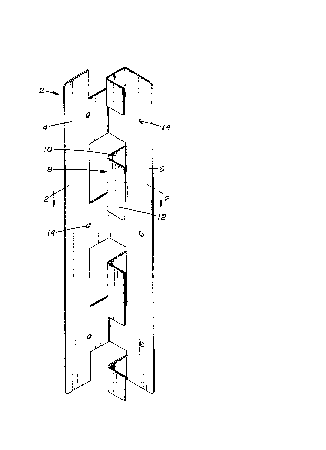
FIG. 1 is an isometric view of the multiple tab embodiment
of the corner angle of the present invention.
FIG. 2 is a cross-sectional view of the corner angle of the
present invention taken along line 2-2 of FIG 1 and additionally
shows how the present invention can be used to join two boards.
FIG. 3 is an isometric view of single tab embodiment of the
corner angle of the present invention.

( 21 ql 041
-
FIG. 4 is a cross-sectional schematic view of the corner
angle of the,present invention where the angle a' between the
connector sidewalls is 120~.
FIG. 5 is a cross-sectional schematic view of the corner
angle of the present invention where the angle a'' between the
connector sidewalls is 135~.
FIG. 6 is a cross-sectional schematic view of the corner
angle of the present invention where the angle a''' between
the connector sidewalls is 60~.
Detailed Description of the Invention
In a preferred embodiment, the present invention is a one
piece metal corner connector for structurally interconnecting
in angular relation to each other two flat rectangular panels
of a given thickness. Referring to Figure 1, it can be seen
that the present invention, referred to generally as corner
angle connector 2, is comprised of a first connector sidewall
4 and a second connector sidewall 6 orientated at angle a to
said first connector sidewall 4. Angle a can be any angle
between 60~ and 135~. A reinforcing tab 8 is stamped out of
,the piece of metal and then bent up so that its first
reinforcing tab sidewall lO is parallel to first connector
sidewall 4 and its second reinforcing tab sidewall 12 is
parallel to the second connector sidewall 6. Apertures 14 are
provided uniformly across the first connector sidewall 4 and
the second connector sidewall 6 to allow the use of nails,

21 91 041
nuts and bolts, screws, rivets, or adhesive to secure the
rectangular panels being joined.
It can be seen in Figure 2 that the spacing~between the
first connector sidewall 4 and the first reinforcing tab
sidewall lO is roughly equal to the thickness of rectangular
panel 16 that is to be joined. The spacing between second
connector sidewall 6 and second reinforcing tab sidewall 12 is
also roughly equal to the thickness of rectangular panel 18
which is to be joined via angle connector 2 to rectangular
panel 16.
Referring back to Figure 1, we can see that multiple
reinforcing tabs 8 are used to support the rectangular panels
to be joined. Figure 3 illustrates another embodiment of the
present invention wherein only a single reinforcing tab 8 is
used to make the corner connection and provide the
reinforcement of the joint. Figures 4 and 5 illustrate other
embodiments of the present invention where the angle a between
the first connector sidewall and second connector sidewall is
in excess of 90~. Either the single, see Figure 1, or
multiple reinforcing, see Figure 3, tab configuration may be
used. In Figure 4, the angle a is approximately 120~. In
Figure 5, angle a is approximately 135~.
The corner angle connector 2 is not limited to joining
two rectangular panels made of wood. It can be used to join
wood, particle board, drywall, plastic or any other material
which is formed into rectangular panels and requires the

- _ ' 21 9 1 041
formation of corner joints and structural support.
Rectangular panels are secured in the corner angle connector
by any number of well known methods. The corner angle
connector can be formed such that the channels between the
connector sidewalls and the reinforcing tab sidewalls are
slightly smaller than the rectangular panels to be joined and
thereby using compression to join and reinforce the
rectangular panels. Nuts and bolts, nails, rivets, or screws
may be passed through apertures 14 to secure panel 16 and
panel 18 to corner angle connector 2. Metal strapping may be
used to bind an assembled box or crate so fabricated. The use
of metal strapping precludes the need for providing any other
form of fastening to keep the panels from folding inward,
which is a common problem with shipping containers when
impacted. Thus fabricated, the box or crate would be easily
disassembled when no longer necessary. It is also within the
scope of the present invention to use an adhesive compatible
with the materials being joined to bond both side surfaces of
the panels to the corner angle connector.

Dessin représentatif
Une figure unique qui représente un dessin illustrant l'invention.
États administratifs

2024-08-01 : Dans le cadre de la transition vers les Brevets de nouvelle génération (BNG), la base de données sur les brevets canadiens (BDBC) contient désormais un Historique d'événement plus détaillé, qui reproduit le Journal des événements de notre nouvelle solution interne.

Veuillez noter que les événements débutant par « Inactive : » se réfèrent à des événements qui ne sont plus utilisés dans notre nouvelle solution interne.

Pour une meilleure compréhension de l'état de la demande ou brevet qui figure sur cette page, la rubrique Mise en garde , et les descriptions de Brevet , Historique d'événement , Taxes périodiques et Historique des paiements devraient être consultées.

Historique d'événement

Description Date
Inactive : CIB de MCD 2006-03-12
Demande non rétablie avant l'échéance 2001-11-22
Le délai pour l'annulation est expiré 2001-11-22
Inactive : Abandon. - Aucune rép dem par.30(2) Règles 2000-11-29
Réputée abandonnée - omission de répondre à un avis sur les taxes pour le maintien en état 2000-11-22
Inactive : Dem. de l'examinateur par.30(2) Règles 2000-05-29
Modification reçue - modification volontaire 1999-02-09
Lettre envoyée 1998-11-05
Inactive : Renseign. sur l'état - Complets dès date d'ent. journ. 1998-11-05
Inactive : Dem. traitée sur TS dès date d'ent. journal 1998-11-05
Exigences pour une requête d'examen - jugée conforme 1998-10-22
Toutes les exigences pour l'examen - jugée conforme 1998-10-22
Demande publiée (accessible au public) 1997-05-23

Historique d'abandonnement

Date d'abandonnement Raison Date de rétablissement
2000-11-22

Taxes périodiques

Le dernier paiement a été reçu le 1999-11-08

Avis : Si le paiement en totalité n'a pas été reçu au plus tard à la date indiquée, une taxe supplémentaire peut être imposée, soit une des taxes suivantes :

  • taxe de rétablissement ;
  • taxe pour paiement en souffrance ; ou
  • taxe additionnelle pour le renversement d'une péremption réputée.

Veuillez vous référer à la page web des taxes sur les brevets de l'OPIC pour voir tous les montants actuels des taxes.

Historique des taxes

Type de taxes Anniversaire Échéance Date payée
TM (demande, 2e anniv.) - générale 02 1998-11-23 1998-10-22
Requête d'examen - générale 1998-10-22
TM (demande, 3e anniv.) - générale 03 1999-11-22 1999-11-08
Titulaires au dossier

Les titulaires actuels et antérieures au dossier sont affichés en ordre alphabétique.

Titulaires actuels au dossier
APA - THE ENGINEERED WOOD ASSOCIATION
Titulaires antérieures au dossier
EDWARD L. KEITH
Les propriétaires antérieurs qui ne figurent pas dans la liste des « Propriétaires au dossier » apparaîtront dans d'autres documents au dossier.
Documents

Pour visionner les fichiers sélectionnés, entrer le code reCAPTCHA :


Pour visualiser une image, cliquer sur un lien dans la colonne description du document. Pour télécharger l'image (les images), cliquer l'une ou plusieurs cases à cocher dans la première colonne et ensuite cliquer sur le bouton "Télécharger sélection en format PDF (archive Zip)" ou le bouton "Télécharger sélection (en un fichier PDF fusionné)".

Liste des documents de brevet publiés et non publiés sur la BDBC .

Si vous avez des difficultés à accéder au contenu, veuillez communiquer avec le Centre de services à la clientèle au 1-866-997-1936, ou envoyer un courriel au Centre de service à la clientèle de l'OPIC.


Description du
Document 
Date
(aaaa-mm-jj) 
Nombre de pages   Taille de l'image (Ko) 
Page couverture 1998-06-25 1 14
Dessin représentatif 1997-11-12 1 20
Page couverture 1997-03-27 1 14
Abrégé 1997-03-27 1 20
Dessins 1997-03-27 1 39
Revendications 1997-03-27 3 86
Description 1997-03-27 7 245
Rappel de taxe de maintien due 1998-07-23 1 115
Accusé de réception de la requête d'examen 1998-11-05 1 177
Courtoisie - Lettre d'abandon (taxe de maintien en état) 2000-12-20 1 183
Courtoisie - Lettre d'abandon (R30(2)) 2001-02-07 1 169
Taxes 1998-10-22 1 31
Taxes 1999-11-08 1 27