Note : Les descriptions sont présentées dans la langue officielle dans laquelle elles ont été soumises.
21915~0
DOCKET NO. 1955/OC525
S
l~EVICE AND METHOD FOR MANUEi'ACTURlNG
A TRANSPQRT ME('~A1~T~I\I FOR Rl1'.T,ATIYELY N~ROW ROT,l,.
BACKGROUN~ gF TI~. INVli'.NTlQN
1. Field of the Inveu~
The present invention relates to a device and a method for manufacturing a
15 transport m~rh~ ;cm for relatively narrow rolls. More specifically, the present invention
relates to a connectmg core that extends through each of the roll cores of the narrow rolls.
The connecting core has an axial length that is approximately equal to the sum of the axial
lengths of each of the narrow rolls. The connecting core is detachably connected at the axial
ends of the comnecting core to only an axial outer two of the narrow rolls.
2. r Qfthe FPlated Art .
Paper is luallura_Lul~d m very wide webs (i.e., the webs of paper are typically
several meters in axial length), but is processed in smaller widths. The same is true for webs
of other materials, such as, fo} example, synthetic material or textiles. To process the wide
25 webs that are woumd on relatively large rolls, the wide webs are cut into narrower webs on
roll slitting machines and are then wound onto several relatively narrow rolls of
2191500
d~luAhll~t~ the same diameter. Problems are frequently ~ ,oul~t~l~d during the subsequent
of these relatively narrow rolls. For example, the narrow rolls are typically
transported on conveyor belts to a packaging stdtion. If the width of the narrow rolls is less
than the diameter of the packdging station, the narrow rolls tend to "wobble" while being
S transported on the conveyor belt due to tbe stdrting and stopping of the conveyor belt.
To prevent the ndrrow rolls from tipping over, paper factories have developed
a trdnsport mechanism thdt is formed from several narrow rolls. An expansion lap rod is
inserted through the roll cores of several narrow rolls, which have been disposed next to each
other. The expansion lap rod is then expanded, by use of a pressure medium, so that each
10 individual narrow roll is clamped to the expanded lap rod. A di~Ad~llLC~, to the use of
expansion lap rods is that they are relatively heavy and are relatively difficult to mAnirlllAtP.
Additionally, expansion lap rods are relatively expensive and require a relatively large amount
of II.A;.I'. .~ lr~ and care. Expansion lap rods hdve conmecting pieces and are relatively long,
so thdt, in some instances, the axial length of the transport mechanism projects beyond the
15 ends of the narrow rolls. Therefore, expansion lap rods hdve an awkward shape. Despite
the fact thdt expansion lap rods are reusable, a significant amount of capitdl is required
because a large number of rods are used and additional rods must be kept as backups in the
paper factory.
Accordingly, it is an object of the present invention to provide a transport
20 mPrh~ni~m thdt is ~ou~;d~lAbly simpler and more cost-effective than expansion lap rods.
2191500
3
SUMMARY OF TI~ TION
This object is achieved by providing a transport mrrh:micnl in which the
transport mechanism includes a plurality of narrow rolls disposed adjacent to one another.
Each of the narrow rolls has a ~ . .",i"~i axial length, is hollow and has an internal
5 diameter that is delimited by a roll core. A connecting core extends through each of the roll
cores. The connecting core has an axial length that is d~)~loAil~ t~ly equal to the sum of the
axial lengths of each of the narrow rolls. The connectimg core is detachably connected at the
axial ends of the connecting core to only two of said roll cores that are the axial outer two
of the narrow rolls.
By connecting the connecting core at its axial ends to only the outer two
narrow rolls, no connection is required to the remaining roll cores. Therefore, the portion
of the connecting core disposed between its axial ends can be designed very simply and,
therefore, can be produced i.o,A~ ,ly. The detachable connection at the axial ends of the
comnecting core can be easily accessed, either manually or ~lltnm~tir~lly, from the outside
15 The connecting core preferably does not project beyond the axial ends of the outer two
narrow rolls, or only far enough so that the area of the detachable comnection can be easily
reached.
Each of the axial ends of the connecting core is slitted. Two stoppers are
detachably connected, one to each of the slitted axial ends of the connecting core so that,
20 when connected, the respective slitted axial end of the connecting core is spread radially
apart. Thus, the detachable connection of the connecting core to the roll cores is achieved
in a relatively simple manner.
21915CO
4
The stoppers preferably have a conical shape and can be made of wood or a
synthetic material, so that they can be produced at a minimal expense. A pair of stoppers are
placed, either manually or ~ nm~tir~llly, adjacent to the open axial ends of the connecting
core. In one ~".I~q~l".,. .,~ an automatic stopper feed device ~ nm~tir:~lly places stoppers
S adjacent to the open axial ends of the connectmg core.
The connectmg core is preferably a one-piece unitary member and, therefore,
forms a continuous connecting core. Thus, the connecting core can be made from continuous
rod material, which is cut to the desired length and, thereafter, is provided with slits at the
axial ends of the comnecting core. The connecting core can be made of, for example,
10 paperboard, which, because it is so iU~,,~).lL)i~., to use, allows for a disposable device.
Two press plate are selectively axially movable to move the plurality of narrow
rolls axially together. A caster is disposed between the two press plates to facilitate the axial
movement of the narrow rolls. The press plates press (i.e., insert) the stqppers into the
slitted axial ends of the connecting core. Once the stoppers have been inserted into the
15 comnecting core, the connecting core is connected to only the ouLer two narrow rolls to form
a compact transport mechanism that has a pdlLiuulduly secure connection Ll..~
A process for . "~, ." r~ ~ ",; "~ a transport mrrh~ m for a plurality of relatively
narrow rolls according to the present invention includes placing a plurality of narrow rolls
next to one another. Each of the narrow rolls has a ~ d axial length and is hollow.
20 Each of the narrow rolls has an internal diameter that is delimited by a roll core. A
connecting core is extended through each of the roll cores. The connecting core has an axial
length that is d~ y equal to the sum of the axial lengths of each of the narrow rolls.
2191500
The connecting core connects the axiai ends of the connecting core only to two of the roll
cores that are the axial outer two of the narrow rolls.
The connecting step provides a detachable clamping connection between the
connecting core and the rolls. This method produces a compact transport mechanism that is
5 comprised of a plurality of narrow rolls in a relatively simple manner.
The plurality of narrow rolls are pushed together axially with a pair of press
plates. The connecting step includes spreading the axial ends of said connectimg core radially
apart. The spreading is achieved by a conically shaped stopper. One of the stoppers is,
manually or ~ )m~ ly, placed into position adjacent to each of the open axial ends of the
10 connecting core. Thercafter, the stoppers are inserted into their final position by the pair of
press plates. Because the stopper is conically shaped, it docs not require any additional
structural elements to conncct the connecting core to the outer two narrow rolls.
In accordance with a furiher aspect of the present invention, the position of the
axes of the narrow rolls is (~ in~ A conically shaped stopper is; lly removed
15 from a stopper magazine and is placcd into position adjacent to each one of the previously
slitted axial ends of the connecting core at the determined position of the axes. Thereafter,
the stoppers are pushed into each of the slitted axial ends, by the press plates, until the
stoppers reach their fulal position.
BRIEF DESCRrPl`IQN OF THE l~RAWIN5~S
The above and still further objects, features and advantages of the present
invention will become apparent upon ~.""~ " of the following detailed description of
a specific el.ll,odh ~ thereof, especially when taken in ~ ; I with the dccolll~)~lyillg
219~500
6
drawings wherein like reference numerals in the various figures are utilized to designate like
~,o~ u.._llb, and wherein:
Figs. 1-5 ~ lly illustrate the individual stages in producing a transport
mPrh~ni~m for relatively narrow rolls accordmg to the present invention; and
Fig. 6 is a partial cross-sectional view through the end of a narrow roll in the
transport mP~honi~m
DETAILED DESCRIPIION OF A PREFERRED EMBODIMENT
Referring now to Figs. 1-6, a transport mP~h~ni~m accordmg to the present
irlvention is illustrated. Four relatively narrow rolls 3, 4, 5 and 6 are illustrated being
delivered from an exit I of a cv~ i()l~l roll slitting machine 2. Rolls 3, 4, 5 and 6 are
delivered by a transport system 7 to an auxiliary device 8. Auxiliary device 8 includes a
caster bed 9 and a pair of press plates 10, 11, one of which is disposed at each axial end of
device 8. Press plates 10, 11 are axially adjustable by the actuation of a piston cylinder units
12, 13, respectively.
The four narrow rolls 3-6 are transferred from the transport device 7 to the
caster bed 9 (See Fig. 2). The four narrow rolls 3-6 are then axially pressed together with.
the aid of press plates 10, 11 (See Fig. 3).
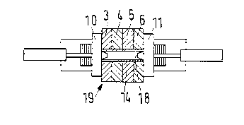
A coDnecting core 14 is inserted through all of the narrow rolls 3-6. Thus,
comnecting core 14 extends through the roll core 15 of each of the narrow rolls 3-6. The
axial ends 16 of the commecting core 14 have slits 17 so that they can be spread apart with the
aid of corlical stoppers 18. When the axial ends of commecting core 16 are spread apart
radially, commecting core 14 is clamped to the ends of the outer two narrow rolls 3 and 6.
2191500
`- 7
A stopper 18 is, manually or Al1~ y, placed in position adjacent to each
of the open axial ends of comnecting core 14 (See Fig. 5). Thereafter, each stopper 18 is
pressed into its final position with t-h-e aid of press plates 10, I l, ~ . Therefore,
coMecting core 14 is clamped only to two of the narrow rolls (i.e., the axial outer two rolls
3, 6). The four narrow rolls 3-6, together with the connecting core 14 and stoppers 18, form
a transport m~rh~ni~m 19 that can be n~ rll ' as a single unit. Therefore, the transport
mechanism is much less likely to tip over, especially during transport, than any individual
narrow roll.
If the narrow rolls that are to be connected to one another have different outer
diameters, a measuring device (not shown) may be used to determine the position of the axis
of the outer two narrow rolls. A feed device removes a pair of stoppers from a stopper
magazine and then, ", ~ y advances the removed stoppers and places them in position,
at the proper height, so that tne stoppers are disposed adjacent to each of the open axial ends
of connecting core 14. Thereafter, stoppers 18 are pressed into the open axial ends of
connecting core 14 by press plates 10, 11.
Having described the presently preferred exemplary 1..l.llO.l;.l.. '~1 device and
method for lI~ llrA- ~-11;11~ a transport mechanism for relatively narrow rolls in accordance
with the present invention, it is believed that other ,,,. .I;r; ~1;'"'`, variations and changes will
be suggested to those skilled in the art in view of the teachings set forth herein. It is,
therefore, to be understood that all such m-l.l;r;~ , variations, and changes are believed
to fall within the scope of the present invention as deflned by the appended claims.