Sélection de la langue

Search

Sommaire du brevet 2191642 

Énoncé de désistement de responsabilité concernant l'information provenant de tiers

Une partie des informations de ce site Web a été fournie par des sources externes. Le gouvernement du Canada n'assume aucune responsabilité concernant la précision, l'actualité ou la fiabilité des informations fournies par les sources externes. Les utilisateurs qui désirent employer cette information devraient consulter directement la source des informations. Le contenu fourni par les sources externes n'est pas assujetti aux exigences sur les langues officielles, la protection des renseignements personnels et l'accessibilité.

Disponibilité de l'Abrégé et des Revendications

L'apparition de différences dans le texte et l'image des Revendications et de l'Abrégé dépend du moment auquel le document est publié. Les textes des Revendications et de l'Abrégé sont affichés :

  • lorsque la demande peut être examinée par le public;
  • lorsque le brevet est émis (délivrance).
(12) Brevet: (11) CA 2191642
(54) Titre français: SUPPORT DE GOUTTIERE
(54) Titre anglais: EAVESTROUGH BRACKET ASSEMBLY
Statut: Durée expirée - au-delà du délai suivant l'octroi
Données bibliographiques
Abrégés

Abrégé français

Un support de gouttière utilise une structure coulissante en deux parties pour fixer le support de gouttière sur une bordure d'avant-toit. Le support de gouttière a une face arrière avec une fente de fixation de rainure s'étendant sur la face arrière. Cette fente reçoit un élément de montage qui a été précédemment fixé à la bordure d'avant-toit. Le support et l'élément de montage sont provisoirement maintenus dans une position de fixation. De préférence, l'élément de montage est un élément allongé fixé par une pluralité de vis à la bordure d'avant-toit.


Abrégé anglais

An eavestrough bracket assembly uses a two-piece sliding structure for mounting the eavestrough bracket to a fascia board. The eavestrough bracket has a back face with an undercut securing slot extending across the back face. This slot receives a mounting member which has been previously secured to the fascia board. The bracket and mounting member are releasably held in a securing position. Preferably, the mounting member is an elongate member secured by a plurality of screws to the fascia board.

Revendications

Note : Les revendications sont présentées dans la langue officielle dans laquelle elles ont été soumises.


THE EMBODIMENTS OF THE INVENTION IN WHICH AN EXCLUSIVE
PROPERTY OR PRIVILEGE IS CLAIMED ARE DEFINED AS FOLLOWS:
1. An eavestrough hook comprising a thin profile
back face and an outwardly extending support arm; said
support arm at a distal end thereof, having a slot
arrangement for engaging and supporting an eavestrough
edge; said support arm adjacent said thin profile back
face including a downwardly opening slot arrangement
adapted to engage and suspend beneath said arm an edge
portion of an eavestrough; and wherein said support arm
is of an inverted "T" section, wherein said arm merges
with an upper portion of said thin profile back face and
includes reinforcing flanges projecting either side of an
upper edge of said support arm and stiffening said
eavestrough hook and providing a high strength area
adjacent said thin profile with said high strength area
including a port for receiving a fastening member.
2. An eavestrough hook as claimed in claim 1
wherein a lower edge of the arm has a curved profile
between said thin profile back face and said distal end.
3. An eavestrough hook as claimed in claim 1
wherein said port is angled downwardly and is positioned
above said downward opening slot arrangement.
4. An eavestrough hook as claimed in claim 1
including at an upper edge of said thin profile back face
a forwardly opening slot and said arm at said distal end
includes a rearward opening slot whereby said slots
provide a fastening arrangement for engaging and
retaining a leaf guard supported by said arm between said
slots.
-7-

5. An eavestrough hook as claimed in claim 1
wherein said support arm adjacent said thin profile back
face includes a recessed top surface for accessing a
securing port passing through said arm and said back
face.
6. An eavestrough hook as claimed in claim 1
wherein said support arm includes a short horizontal
flange on an upper edge of said support arm adjacent said
thin profile back face and extending forwardly towards
said distal end, said short horizontal flange cooperating
with said support arm to provide a high strength area
joining said support arm to said back face above said
downwardly opening slot arrangement.
7. An eavestrough hook as claimed in claim 5
wherein a lower surface of said support arm extends
inwardly and upwardly within said downwardly opening slot
arrangement for engaging and supporting a rear edge of a
length of eavestrough.
8. An eavestrough hook as claimed in claim 1, 2,
3, 4, 5 or 6 wherein said eavestrough hook is of a one
piece integral construction.
9. An eavestrough hook as claimed in claim 1
wherein said support arm adjacent said thin profiled back
face includes a recess cavity and said reinforcing
flanges extend across said recess cavity, said
reinforcing flanges being supported by a downwardly
angled reinforcing section about said port that joins
said reinforcing flanges and said thin profiled back
face.
-8-

Description

Note : Les descriptions sont présentées dans la langue officielle dans laquelle elles ont été soumises.

WH-9611CA '
2191642
TITLE: EAVESTROUGH BRACKET ASSEMBLY
FIELD OF THE INVENTION
The present invention relates to an eavestrough
bracket assembly for supporting an eavestrough to one side
of a fascia board. In particular, the invention relates to
an eavestrough bracket assembly comprising a mounting
member for attachment to a fascia board and an eavestrough
hook adapted to be secured from the mounting member.
BACKGROUND OF THE INVENTION
There are many systems for securing of eavestroughs
from a fascia board and many of these systems can be
divided into systems which use metal components or systems
which use plastic components. One of the critical steps in
installing an eavestrough system is to secure the
eavestrough sections at various points along their length
in a desired manner to ensure proper drainage.
Essentially, all installation procedures include setting a
particular grade line along the fascia board and then
securing eavestrough hooks at appropriate positions. Some
systems allow these eavestrough hooks to be secured first
to the fascia board and then the eavestrough secured to the
hooks, or in other cases, the eavestrough hooks are
essentially secured when the hooks are already attached to
the eavestrough.
To simplify the installation process, one of our
earlier systems included securing a mounting tab to the
fascia board and these mounting tabs were adapted to
receive and support the eavestrough hook. In this way, the
mounting tabs could be secured to the fascia board and then
the eavestrough sections and eavestrough hooks could be
- 1 -

CA 02191642 2004-07-13
secured to the various mounting tabs. The eavestrough
hooks were secured within a V-shaped slot of the mounting
tab and the mounting tab included detent members for
holding the eavestrough hook in position. Under certain
high load conditions, there could be failure of these
mounting tabs. In addition, because the eavestrough
hooks were inserted into the tabs from above, the
eavestrough section could not be as close to the shingles
of the roof as may be desirable. Furthermore, the
eavestrough sections were spaced off of the fascia board
by the thickness of the back face of the tab and there
was a gap between the back of the eavestrough section and
the fascia board.
The present invention seeks to overcome a number
of the above deficiencies while continuing to provide a
system which is easy to install.
SUMMARY OF THE INVENTION
An eavestrough hook according to the present
invention comprises a thin profile back face and an
outwardly extending support arm. The support arm at a
distal end thereof, has a slot arrangement for engaging
and supporting an eavestrough edge. The support arm
adjacent the thin profile back face includes a downwardly
opening slot arrangement adapted to engage and suspend
beneath the arm an edge portion of the eavestrough. The
support arm is of an inverted "T" section and a lower
edge of the arm has a curved profile between the thin
profile back face and the distal end.
According to an aspect of the invention, the
arm merges with an upper portion of the thin profile back
face and includes reinforcing flanges projecting either
side of the support arm and stiffening the eavestrough
-2-

CA 02191642 2004-07-13
WH-9611CA
hook. This arrangement provides a high strength area
adjacent the thin profile with the high strength area
including a port for receiving a fastening member.
In a further aspect of the invention, the port
is angled downwardly and is positioned above the downward
opening slot arrangement.
In a further aspect of the invention, the
eavestrough hook includes at an upper edge of the thin
profile back face, a forwardly opening slot and the arm
at the distal end includes a rearward opening slot
whereby the slots provide a fastening arrangement for
engaging and retaining a leaf guard supported by the arm
between the slots.
An eavestrough hook according to a different
aspect of the invention has a high strength area where
the support arm merges with the thin profile back face.
A recessed surface in an upper surface of the support arm
provides access to the securing port.
In yet a further aspect of the invention, the
support arm includes a short horizontal flange on an
upper edge of the support arm adjacent the thin profile
back face that extends forwardly towards the distal end.
The short horizontal flange cooperating with the support
arm to provide a high strength area joining the support
arm to the back face above the downwardly opening slot
arrangement.
BRIEF DESCRIPTIONS OF THE DRAWINGS
Preferred embodiments of the invention are shown
in the drawings, wherein:
-3-

CA 02191642 2004-07-13
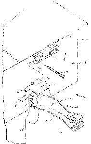
Figure 1 is an exploded perspective view of the
eavestrough hook assembly being attached to a fascia
board;
Figure 2 is a side view showing an eavestrough
section supported from the eavestrough bracket assembly;
Figure 3 is a perspective view showing the rear
surface of the mounting member and the back face of the
eavestrough hook;
Figure 4 is a partial perspective view showing
an eavestrough section and the manner of securement to
the eavestrough hook;
-3a-

CA 02191642 2004-07-13
WH-9611CA
Figure 5 is a sectional view through the mounting
member;
Figure 6 shows the spring tabs of the mounting
member engaging the arm portion of the eavestrough hook;
and
Figures 7 and 8 show a one-piece eavestrough hook.
DETAILED DESCRIPTION OF THE PREFERRED EMBODIMENTS
The eavestrough bracket assembly 2 includes an
elongate mounting member 4 having three ports 6 for
receiving screw fasteners 8. The screw fasteners positively
secure the mounting member to the fascia board 1.
An eavestrough hook 20 is adapted to be slidable on
the elongate mounting member 4 to positively secure the
eavestrough hook in a perpendicular manner to the mounting
member and to the fascia board. The back face 24 of the
eavestrough hook has an undercut slot 22. Projecting into
the slot 22 is the upper shoulder 26 and the lower shoulder
28. The mounting member 4, as shown in Figure 3, also has
upper shoulders 10 and lower shoulders 12 either side of
the mounting projections 14. The mounting projections 14
serve to space the shoulders 10 and 12 off the face of the
fascia board and provide room for receiving the upper and
lower shoulders 26 and 28 of the eavestrough hook. With
this arrangement, the eavestrough hook 2 is slidable on the
mounting member 4 and is retained in a center position on
the mounting member by spring tabs 16.
The eavestrough hook has a top flange 30 which
supports and stiffens the upper shoulder 26 and this upper
flange merges with the web 34 of the arm 32. At the bottom
edge of the web 34 is the lower flange 36. The web and
lower flange define an inverted "T" type structure and
stiffen arm 32. The lower flange 36 is bowed upwardly and
- 4 -

CA 02191642 2004-07-13
WH-9611CA
is compressed under the high loads. At the distal end of
the arm 32 is the front eavestrough engaging section 40
which cooperates with the rear eavestrough engaging section
42 to allow hanging of the eavestrough 60 from the front
and rear upper edges. The eavestrough is slidable along
these engaging sections.
Figure 5 illustrates the front face of the mounting
member 4 and the spring tabs 16. The eavestrough hook is
inserted on one end of the mounting member 4 and as it is
moved along the mounting member, the first spring tab 16 is
forced inwardly. This allows the back face of the
eavestrough hook to clear the spring tab and allow it to
eventually move outwardly to an overlapped position, as
shown in Figure 6. Thus, the spring tabs 16 cooperate with
section 39, as shown in Figure 6, of the arm 32 to
positively locate the eavestrough hook on the mounting tab.
It can be appreciated that the eavestrough hook can be
removed by depressing one of the spring tabs 16 and sliding
the eavestrough hook off of the mounting member.
As shown in Figure 1, the mounting members 4 may be
secured to the fascia board at appropriate locations along
the length of the fascia board and at an appropriate height
below the shingles 3. The eavestrough hooks can be
inserted on an eavestrough section and slide therealong to
the appropriate position. The eavestrough section and
hooks are then brought up to the fascia board where the
mounting tabs have already been secured at the appropriate
locations. The eavestrough hooks can then be secured to
the fascia board 1 by sliding the eavestrough hooks onto
the mounting members. Securement of two hooks will support
the eavestrough section and the remaining hooks can then be
secured. This provides a simple means for securing of the
eavestrough section on the fascia board, which does not
require tools after the mounting member has been secured.
The eavestrough hook 100 of Figures 7 and 8 is a
single piece design having a thin profile back face 102.
- 5 -

CA 02191642 2004-07-13
WH-9611CA
The arm 104 is of the inverted 'T' design and the
eavestrough is supported in the same manner.
A screw 110 is inserted in port 112 which has a
reinforced section 114 intermediate the recessed flanged
area 116 and the back wall flange 118, the web 120 and
stepped flange 120. With this arrangement, the eavestrough
hook is of high strength to meet the required securing
loads. The port 112 is angled downwardly at about a 30°
angle to avoid pullout of screw 110. The downward
extending section 122 provides a convenient thumb and
finger gripping area used during securement of the hook.
Tabs 130, 132, 134 and 136, support face 138 and
recess 140 are used to secure accessories, such as drip
edge and leaf guard.
The design shown in Figures 1 through 6 and the
design shown in Figures 7 and 8 at the inner upper region
of the hook is stiff with a thin flexible grasping portion
and guard therebelow.
Although various preferred embodiments of the
present invention have been described herein in detail, it
will be appreciated by those skilled in the art, that
variations may be made thereto without departing from the
spirit of the invention or the scope of the appended
claims.
- 6 -

Dessin représentatif
Une figure unique qui représente un dessin illustrant l'invention.
États administratifs

2024-08-01 : Dans le cadre de la transition vers les Brevets de nouvelle génération (BNG), la base de données sur les brevets canadiens (BDBC) contient désormais un Historique d'événement plus détaillé, qui reproduit le Journal des événements de notre nouvelle solution interne.

Veuillez noter que les événements débutant par « Inactive : » se réfèrent à des événements qui ne sont plus utilisés dans notre nouvelle solution interne.

Pour une meilleure compréhension de l'état de la demande ou brevet qui figure sur cette page, la rubrique Mise en garde , et les descriptions de Brevet , Historique d'événement , Taxes périodiques et Historique des paiements devraient être consultées.

Historique d'événement

Description Date
Inactive : Périmé (brevet - nouvelle loi) 2016-11-29
Lettre envoyée 2011-04-19
Lettre envoyée 2009-05-28
Lettre envoyée 2007-10-26
Inactive : Lettre officielle 2007-04-26
Inactive : Lettre officielle 2007-04-13
Lettre envoyée 2006-09-22
Accordé par délivrance 2005-08-09
Inactive : Page couverture publiée 2005-08-08
Préoctroi 2005-05-25
Inactive : Taxe finale reçue 2005-05-25
Un avis d'acceptation est envoyé 2005-03-30
Lettre envoyée 2005-03-30
Inactive : Approuvée aux fins d'acceptation (AFA) 2005-03-17
Modification reçue - modification volontaire 2005-02-17
Inactive : Dem. de l'examinateur par.30(2) Règles 2004-08-31
Modification reçue - modification volontaire 2004-07-13
Inactive : Dem. de l'examinateur art.29 Règles 2004-01-14
Inactive : Dem. de l'examinateur par.30(2) Règles 2004-01-14
Inactive : Dem. traitée sur TS dès date d'ent. journal 2001-05-23
Inactive : Renseign. sur l'état - Complets dès date d'ent. journ. 2001-05-23
Lettre envoyée 2001-05-10
Toutes les exigences pour l'examen - jugée conforme 2001-04-20
Exigences pour une requête d'examen - jugée conforme 2001-04-20
Modification reçue - modification volontaire 2001-04-20
Demande publiée (accessible au public) 1998-05-29

Historique d'abandonnement

Il n'y a pas d'historique d'abandonnement

Taxes périodiques

Le dernier paiement a été reçu le 2004-10-18

Avis : Si le paiement en totalité n'a pas été reçu au plus tard à la date indiquée, une taxe supplémentaire peut être imposée, soit une des taxes suivantes :

  • taxe de rétablissement ;
  • taxe pour paiement en souffrance ; ou
  • taxe additionnelle pour le renversement d'une péremption réputée.

Veuillez vous référer à la page web des taxes sur les brevets de l'OPIC pour voir tous les montants actuels des taxes.

Titulaires au dossier

Les titulaires actuels et antérieures au dossier sont affichés en ordre alphabétique.

Titulaires actuels au dossier
GSW INC.
EURAMAX CANADA, INC.
Titulaires antérieures au dossier
GARY WAYNE FORTIN
Les propriétaires antérieurs qui ne figurent pas dans la liste des « Propriétaires au dossier » apparaîtront dans d'autres documents au dossier.
Documents

Pour visionner les fichiers sélectionnés, entrer le code reCAPTCHA :


Pour visualiser une image, cliquer sur un lien dans la colonne description du document. Pour télécharger l'image (les images), cliquer l'une ou plusieurs cases à cocher dans la première colonne et ensuite cliquer sur le bouton "Télécharger sélection en format PDF (archive Zip)" ou le bouton "Télécharger sélection (en un fichier PDF fusionné)".

Liste des documents de brevet publiés et non publiés sur la BDBC .

Si vous avez des difficultés à accéder au contenu, veuillez communiquer avec le Centre de services à la clientèle au 1-866-997-1936, ou envoyer un courriel au Centre de service à la clientèle de l'OPIC.


Description du
Document 
Date
(aaaa-mm-jj) 
Nombre de pages   Taille de l'image (Ko) 
Dessin représentatif 1998-05-30 1 10
Revendications 2001-04-20 3 99
Description 1997-05-05 6 244
Abrégé 1997-05-05 1 15
Page couverture 1997-05-05 1 15
Revendications 1997-05-05 2 52
Page couverture 1998-05-30 1 42
Dessins 1997-01-07 4 167
Description 2004-07-13 7 274
Revendications 2004-07-13 2 81
Revendications 2005-02-17 2 80
Dessins 1997-05-05 4 101
Dessin représentatif 2005-03-29 1 9
Page couverture 2005-07-26 2 37
Rappel de taxe de maintien due 1998-07-30 1 115
Accusé de réception de la requête d'examen 2001-05-10 1 178
Avis du commissaire - Demande jugée acceptable 2005-03-30 1 162
Correspondance 1997-01-07 6 211
Correspondance 2005-05-25 1 33
Correspondance 2006-10-27 17 697
Correspondance 2007-04-13 1 15
Correspondance 2007-04-26 1 15