Sélection de la langue

Search

Sommaire du brevet 2192059 

Énoncé de désistement de responsabilité concernant l'information provenant de tiers

Une partie des informations de ce site Web a été fournie par des sources externes. Le gouvernement du Canada n'assume aucune responsabilité concernant la précision, l'actualité ou la fiabilité des informations fournies par les sources externes. Les utilisateurs qui désirent employer cette information devraient consulter directement la source des informations. Le contenu fourni par les sources externes n'est pas assujetti aux exigences sur les langues officielles, la protection des renseignements personnels et l'accessibilité.

Disponibilité de l'Abrégé et des Revendications

L'apparition de différences dans le texte et l'image des Revendications et de l'Abrégé dépend du moment auquel le document est publié. Les textes des Revendications et de l'Abrégé sont affichés :

  • lorsque la demande peut être examinée par le public;
  • lorsque le brevet est émis (délivrance).
(12) Demande de brevet: (11) CA 2192059
(54) Titre français: DISPOSITIF DE PRESSAGE DE PLASTIQUES
(54) Titre anglais: A DEVICE FOR PRESSING PLASTICS
Statut: Réputée abandonnée et au-delà du délai pour le rétablissement - en attente de la réponse à l’avis de communication rejetée
Données bibliographiques
(51) Classification internationale des brevets (CIB):
  • B29C 43/52 (2006.01)
  • B29C 43/04 (2006.01)
(72) Inventeurs :
  • LEEB, KARL-ERIK (Suède)
(73) Titulaires :
  • TELEFONAKTIEBOLAGET LM ERICSSON
(71) Demandeurs :
  • TELEFONAKTIEBOLAGET LM ERICSSON (Suède)
(74) Agent: MARKS & CLERK
(74) Co-agent:
(45) Délivré:
(86) Date de dépôt PCT: 1995-06-08
(87) Mise à la disponibilité du public: 1995-12-21
Licence disponible: S.O.
Cédé au domaine public: S.O.
(25) Langue des documents déposés: Anglais

Traité de coopération en matière de brevets (PCT): Oui
(86) Numéro de la demande PCT: PCT/SE1995/000687
(87) Numéro de publication internationale PCT: WO 1995034419
(85) Entrée nationale: 1996-12-04

(30) Données de priorité de la demande:
Numéro de la demande Pays / territoire Date
9402085-6 (Suède) 1994-06-14

Abrégés

Abrégé français

L'invention concerne un appareil de pressage de plastiques comprenant un outil de pressage destiné à être pressé contre une surface de pressage chauffée ou refroidie et régulée par thermostat, à l'aide d'un moyen de pression. La surface de pressage comporte une surface plane commune à un dispositif froid régulé par thermostat (2) et à un dispositif chaud régulé par thermostat (3), et l'outil (10) peut être déplacé d'un dispositif régulé par thermostat (2) à l'autre dispositif régulé par thermostat (3), l'invention permettant de modifier rapidement la température de l'outil (10) et de la pièce de plastique qu'il contient, et ce en même temps que la pression est appliquée.


Abrégé anglais


The present invention relates to plastic pressing apparatus comprising a press
tool which is adapted to be pressed against a thermostat-controlled heated or
cooled press surface with the aid of pressure means. According to the
invention, the press surface includes a flat surface which is common to a
thermostat-controlled cold device (2) and a thermostat-controlled hot device
(3), and the tool (10) can be moved from one thermostat-controlled device (2)
to the other thermostat-controlled device (3) with the invention of varying or
modifying the temperature of the tool (10) and the plastic workpiece enclosed
therein quickly and at the same time as the pressure is applied.

Revendications

Note : Les revendications sont présentées dans la langue officielle dans laquelle elles ont été soumises.


CLAIMS
1. An apparatus for pressing plastic at rapidly varying
temperatures, comprising a press tool which is adapted to be
pressed against a thermostat-controlled heated or cooled
press surface with the aid of pressure means, characterized in
that the press surface includes a flat surface which is common
to a thermostat-controlled cold device (2) and a thermostat-controlled
hot device (3); in that the press tool (10) can be
moved along the press surface common to said thermostat-controlled
devices (2, 3) while maintaining the pressure
applied by the press device (7), wherein the temperature of
the press tool (10) is changed by thermal contact with the
thermostat-controlled devices (2, 3).
2. An apparatus according to Claim 1, characterized in that
the press tool (10) has a flat surface which when pressure is
applied thereto abuts the press surface common to said
thermostat-controlled devices (2, 3) and slides against said
press surface, wherein the press tool (10) is brought into
contact with the cold thermostat controlled device (2) in one
position of its movement against said surface and into contact
with the hot thermostat-controlled device (3) in another
position of its movement against said surface.
3. An apparatus according to Claim 1 or Claim 2, characterized
in that the surfaces that are brought into mutual
abutment upon applying said pressing force are coated with a
substance which reduces friction and enhances thermal
conductivity.
4. An apparatus according to Claim 1, characterized in that
the cold thermostat-controlled device (2) is cooled with cold
fluid which circulates in a cooling channel (14) and the hot
thermostat-controlled device (3) is heated by means of an
electric heating element (13), wherein the energy flows are

controlled so that an essentially even temperature will
prevail in respective devices.
5. An apparatus according to Claim 1, characterized in that
the thermostat-controlled devices (2, 3) are mutually
separated by a heat-insulating material (4).

Description

Note : Les descriptions sont présentées dans la langue officielle dans laquelle elles ont été soumises.

~ ~ WO95/3~19 2 1 9 2 0 5 9 PCTISE9S/00687
A DEVICE FOR PRESSING PLASTICS
TEC~NICAL FIELD
The present invention relates to plastic pressing apparatus
which includes a rapid heating and cooling facility.
TEC~NICAL FIELD
There is often a need to heat and cool a plastic workpiece,
_ particularly a thermoplastic workpiece, while applying pres-
sure thereto. This need often exists when wishing to obtain
particularly fine surfaces on the workpiece, or when encap-
sulating electronics in screening or shielding laminates that
are comprised of thermoplastic foils and metal foils and where
electrical contacting is desired, as described in Swedish
Specification 9300966-0.
In the case of existing plastic pressing apparatus, the
desired pressure is often generated with the aid of hydraulic
piston-cylinder devices, where the force is distributed over
the tool through the medium of a steel pressure plate. The
pressure plate must be relatively thick, in order to have the
rigidity necessary to distributeauniform pressure forceover
the whole of the surface to be pressed, particularly when
pressing workpieces of large surface areas.
In the case of present-day pressing apparatus, the whole of
the pressure exerting plate, or at least a significant part of
the plate, is thermostat-controlled so as to adjust the
temperature to a desired level. The plate, which thus also
transmits heat, is often provided with passageways through
which attemperated liquid is flushed. The plate may alterna-
tively be heated with the aid of electric heating elements
placed in direct thermal contact with the pressure-exerting
plate.

WO95/31~l9 2 1 9 2 0 5 9 PCT/SE~100687
When theprocess is to be carried out at varying temperatures,
existing apparatus have the limitation that the relatively
large volumes of material5 which make up the pressure and
heat-transmitting plate, the tool and the workpiece require
the input of large quantities of energy to change the tempera-
ture of the material, and that this energy flow is limited to
the energy that can be developed in electrical heating
elements for instance, and also by the rate of the temperature
changeofthethermal resistances present in theconstruction,
these resistances often being dominated by contact resistan-
ces between various parts.
As a result, the total heating time and cooling time in a
press for pressing a flat laminate at a pressure of 500 N/cm2
is often in the order of thirty minutes. When pressing
thermoplasticplateswherethe material itselfa~fords a rapid
working cycle, the slow temperature change constitutes a
serious drawback from a production-economic aspect.
5U~ARY OF T/IE INVENTION
An object of the present invention is to provide a plastic
pressing apparatus Which solves the aforesaid proble~
associated with the use of state-of-the-art techniques.
The apparatus is comprised of several thermostat-controlled-
devices against which a pressing tool can be pressed by a tool
holder, wherein the tool can be moved between the ~h~ ~at-
controlled devices while maintaining a pressing force, andwherein a large part of the tool surface comes into contact
with the thermostat-controlled device. ~he surfaces of the
thermostat-controlled device and that part of the pressing
tool that lies against said device are lubricated so as to
reduce friction and the thermal resistance.

~ ~ WO95/34419 2 1 9 2 0 5 9 PCT/SE95/00687
As a result of the construction of the inventive apparatus,
only a minimum amount of material is subjected to temperature
variations, meaning that only small quantities of energy are
required to effect such variations, and thejoints between the
thermostat-controlled device and the tool have low thermal
resistance, and theth~ at-controlled device can be given
a large mass which functions a5 a thermal buffer.
The time taken to effect these variations in temperature i5
consequently very short and thus results in a speedy manufac-
turing cycle, which solves a serious problem associated withpresent-day plastic pressing apparatus.
The invention will now be described in more detail with
reference to a preferred exemplifying embodiment thereof and
also with reference to the accompanying drawing.
8RIEF DESCRIPTION OF ~XE DR~WING
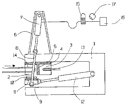
Figure l is a side view of one embodiment of an inventive
apparatus.
Figure 2 is a side view of another embodiment of the inventive
apparatus.
BEST ~ODES OF CARRYING O~T TXE INVENTION
Two exemplifying r-~o~ nts of the invention are described
below with reference to the accompanying drawing. The descri-
bed embodiments can be varied in different ways and the
invention is therefore restricted solely by the contents of
the following Claims.
Figure l shows a stand l which has mounted in its upper part
a thermostat-controlled cold device 2 and a thermostat-
controlled hot device 3, said devices being affixed to the

WO95/34419 2 1 9 2 0 5 9 PCT/SE95/00687
stand 1 through the medium of heat-insulating material 4. The
two thermostat-COntrOlled devices 2, 3 are separated from one
another by heat-insulating material 5. Mounted centrally on
the frame 1, vertically above the thermostat-controlled
devices 2, 3, is a pedestal 6 which forms a mounting for a
hydraulic piston-cylinder apparatus 7 which functions to
exert a pulling force on a tool holder 9 through the medium of
a yoke 8.
The force applied by the hydraulic cylinder 7 presses a press
tool 10 between the tool holder 9 and the the ,Lat-con-
trolled devices 2, 3. The tool holder 9 is thermally insulated
from the tool 10 by means of thermally insulating material 11.
The tool holder 9 and the tool 10 carried thereby can be moved
between the cold th~ - Lat-controlled device 2 and the hot
th~l Lat-controlleddevice3 bymeans of ahydraulicpiston-
cylinder apparatus 12, wherewith the tool 10 slides on a film
of lubricant on the undersurfaces of the thermostat-control-
led devices 2, 3, these surfaces being flat and parallel.
Fnergy is supplied to the hot thermostat-controlled device 3
from an electric heating element 13, whereas the cold thermos-
tat-control device 2 is cooled with cold fluid circulated in
a cooling channel 14, the energy flows being regulated 50 that
an essentially uniform temperaturewillprevail in the devices
2, 3.
The yoke 8 and the hydraulic cylinder 7 form a pendulum, with
the tool holder 9 attached to the outer end thereof. As the
pendulum swings towards the flat thermostat-controlled
devices 2, 3, the working length of the hydraulic cylinder 7
will change during the working cycle of the apparatus.-In
order to compensate for this change in length and also in
order to maintain a constant pressure, the a~L~Lus includes
a hydraulic accumulator 15 between the hydraulic pump 16
supplying hydraulic fluids to the cylinder 7 and said cylin-

. ~ ~VO95/3~19 2 1 9 2 0 5 9 PCT/SE95/00687
der. The oil pressure, and therewith the press pressure,between the tool holder and the thermostat-controlled devices
2, 3 can be read-off from a manometer 17.
In a typical working cycle of the apparatus, the pistons of
the hydraulic piston-cylinder apparatus 12, 7 are initially
in their respective extended positions. The tool lO carrying
the material to be worked is placed on top of the tool holder
g and the hydraulic cylinder 7 is activated, wherewith
pressure is exerted against the cold thermostat-controlled
device. The tool holder 9 is then drawn over to the hot
thermostat-controlled device 3, by means of the hydrau .
piston-cylinder apparatus 12. When the -temperature of the
material carried by the tool lO has risen to the level
desired, the tool holder 9 and the tool lO are moved back to
theth~ - ~dt-controlled cold device2, and when thetempera-
ture in the material has fallen to the level desired, the
hydraulic cylinder 7 is expanded and the tool holder 9
therewith lowered so that the tool 10 can be removed.
The tool 10 may be provided with a thermometer, to enable the
temperature of the tool to be checked. The temperature of the
thermostat-controlled hot device 3 may be considerably higher
thanthe highest tool temperature, and the tool temperatureis
adjusted by moving the tool holder 9 back to the cold thermos-
tat-controlled device 2 immediately the tool 10 is heated to
a maximum temperature. This facility permits a considerably
large difference in temperature between the thermostat-
controlled devices 2, 3 and the tool 10, resulting in a larger
heat flow and ~uic~er temperature adjustment.
Figure 2 illustrates a variant of the apparatus in which the
thermostat-controlled devices 2, 3, the tool holder 9, the
tool 10 and the hydraulic piston-cylinder device 12 are
arranged in the same manner as in the Figure 1 embodiment. In
the Figure 2 embodiment, the pressing force is obtained

WO95/3~19 2 1 9 2 0 5 9 PCT/SE95/00687
through the medium of a hydraulic piston-cylinder device 18
which acts between the bottom and the upper leg of the stand
24. The hydraulic piston-cylinder device 18 is mounted on a
carriage 19 which runs on rollers 20 along guides 21. The
upper and the lower leg of the stand 24 are held together by
a draw bolt 22.
Minor variations in the volume of the hydraulic piston-
cylinder device 18 caused by variations in the measurements
between the guides 21 and the thermostat-controlled devices
2, 3 are c~ ,~ncated for with the aid of a hydraulic accu~u-
lator 23.
It will be understood that the invention is not restricted to
the aforedescrlbed and illustrated exemplifyingt~h~tli~-nts
thereof and that modifications can be made within the scope of
the following Claims.

Dessin représentatif
Une figure unique qui représente un dessin illustrant l'invention.
États administratifs

2024-08-01 : Dans le cadre de la transition vers les Brevets de nouvelle génération (BNG), la base de données sur les brevets canadiens (BDBC) contient désormais un Historique d'événement plus détaillé, qui reproduit le Journal des événements de notre nouvelle solution interne.

Veuillez noter que les événements débutant par « Inactive : » se réfèrent à des événements qui ne sont plus utilisés dans notre nouvelle solution interne.

Pour une meilleure compréhension de l'état de la demande ou brevet qui figure sur cette page, la rubrique Mise en garde , et les descriptions de Brevet , Historique d'événement , Taxes périodiques et Historique des paiements devraient être consultées.

Historique d'événement

Description Date
Inactive : CIB de MCD 2006-03-12
Le délai pour l'annulation est expiré 2003-06-09
Demande non rétablie avant l'échéance 2003-06-09
Inactive : Renseign. sur l'état - Complets dès date d'ent. journ. 2002-07-23
Inactive : Abandon.-RE+surtaxe impayées-Corr envoyée 2002-06-10
Réputée abandonnée - omission de répondre à un avis sur les taxes pour le maintien en état 2002-06-10
Demande publiée (accessible au public) 1995-12-21

Historique d'abandonnement

Date d'abandonnement Raison Date de rétablissement
2002-06-10

Taxes périodiques

Le dernier paiement a été reçu le 2001-05-29

Avis : Si le paiement en totalité n'a pas été reçu au plus tard à la date indiquée, une taxe supplémentaire peut être imposée, soit une des taxes suivantes :

  • taxe de rétablissement ;
  • taxe pour paiement en souffrance ; ou
  • taxe additionnelle pour le renversement d'une péremption réputée.

Veuillez vous référer à la page web des taxes sur les brevets de l'OPIC pour voir tous les montants actuels des taxes.

Historique des taxes

Type de taxes Anniversaire Échéance Date payée
TM (demande, 3e anniv.) - générale 03 1998-06-08 1998-06-03
TM (demande, 4e anniv.) - générale 04 1999-06-08 1999-05-31
TM (demande, 5e anniv.) - générale 05 2000-06-08 2000-05-30
TM (demande, 6e anniv.) - générale 06 2001-06-08 2001-05-29
Titulaires au dossier

Les titulaires actuels et antérieures au dossier sont affichés en ordre alphabétique.

Titulaires actuels au dossier
TELEFONAKTIEBOLAGET LM ERICSSON
Titulaires antérieures au dossier
KARL-ERIK LEEB
Les propriétaires antérieurs qui ne figurent pas dans la liste des « Propriétaires au dossier » apparaîtront dans d'autres documents au dossier.
Documents

Pour visionner les fichiers sélectionnés, entrer le code reCAPTCHA :


Pour visualiser une image, cliquer sur un lien dans la colonne description du document. Pour télécharger l'image (les images), cliquer l'une ou plusieurs cases à cocher dans la première colonne et ensuite cliquer sur le bouton "Télécharger sélection en format PDF (archive Zip)" ou le bouton "Télécharger sélection (en un fichier PDF fusionné)".

Liste des documents de brevet publiés et non publiés sur la BDBC .

Si vous avez des difficultés à accéder au contenu, veuillez communiquer avec le Centre de services à la clientèle au 1-866-997-1936, ou envoyer un courriel au Centre de service à la clientèle de l'OPIC.


Description du
Document 
Date
(aaaa-mm-jj) 
Nombre de pages   Taille de l'image (Ko) 
Dessin représentatif 1999-06-11 1 9
Abrégé 1995-12-21 1 16
Page couverture 1997-05-07 1 14
Description 1995-12-21 6 242
Revendications 1995-12-21 2 53
Dessins 1995-12-21 1 18
Page couverture 1998-06-23 1 14
Rappel - requête d'examen 2002-02-11 1 117
Courtoisie - Lettre d'abandon (taxe de maintien en état) 2002-07-08 1 183
Courtoisie - Lettre d'abandon (requête d'examen) 2002-07-22 1 170
Taxes 1997-05-14 1 82
Rapport d'examen préliminaire international 1996-12-04 18 606