Sélection de la langue

Search

Sommaire du brevet 2192185 

Énoncé de désistement de responsabilité concernant l'information provenant de tiers

Une partie des informations de ce site Web a été fournie par des sources externes. Le gouvernement du Canada n'assume aucune responsabilité concernant la précision, l'actualité ou la fiabilité des informations fournies par les sources externes. Les utilisateurs qui désirent employer cette information devraient consulter directement la source des informations. Le contenu fourni par les sources externes n'est pas assujetti aux exigences sur les langues officielles, la protection des renseignements personnels et l'accessibilité.

Disponibilité de l'Abrégé et des Revendications

L'apparition de différences dans le texte et l'image des Revendications et de l'Abrégé dépend du moment auquel le document est publié. Les textes des Revendications et de l'Abrégé sont affichés :

  • lorsque la demande peut être examinée par le public;
  • lorsque le brevet est émis (délivrance).
(12) Brevet: (11) CA 2192185
(54) Titre français: PROCEDE PERMETTANT DE PLACER UN SIFFLET DEVIATEUR DANS UN PUITS DE FORAGE
(54) Titre anglais: METHOD FOR SETTING A WHIPSTOCK IN A WELLBORE
Statut: Durée expirée - au-delà du délai suivant l'octroi
Données bibliographiques
(51) Classification internationale des brevets (CIB):
  • E21B 23/00 (2006.01)
  • E21B 07/06 (2006.01)
(72) Inventeurs :
  • BLOUNT, CURTIS G. (Etats-Unis d'Amérique)
  • HIGHTOWER, CHARLES M. (Etats-Unis d'Amérique)
  • HAILEY, CHARLES D. (Etats-Unis d'Amérique)
(73) Titulaires :
  • PHILLIPS PETROLEUM COMPANY
  • ATLANTIC RICHFIELD COMPANY
  • CHARLES D. HAILEY
(71) Demandeurs :
  • PHILLIPS PETROLEUM COMPANY (Etats-Unis d'Amérique)
  • ATLANTIC RICHFIELD COMPANY (Etats-Unis d'Amérique)
  • CHARLES D. HAILEY (Etats-Unis d'Amérique)
(74) Agent: NORTON ROSE FULBRIGHT CANADA LLP/S.E.N.C.R.L., S.R.L.
(74) Co-agent:
(45) Délivré: 2001-07-24
(86) Date de dépôt PCT: 1995-05-25
(87) Mise à la disponibilité du public: 1995-12-14
Requête d'examen: 1997-06-05
Licence disponible: S.O.
Cédé au domaine public: S.O.
(25) Langue des documents déposés: Anglais

Traité de coopération en matière de brevets (PCT): Oui
(86) Numéro de la demande PCT: PCT/GB1995/001196
(87) Numéro de publication internationale PCT: GB1995001196
(85) Entrée nationale: 1996-12-05

(30) Données de priorité de la demande:
Numéro de la demande Pays / territoire Date
08/254,714 (Etats-Unis d'Amérique) 1994-06-06

Abrégés

Abrégé français

Un procédé permet de placer un sifflet déviateur (25) dans un puits de forage (2) sur un ancrage-garniture d'étanchéité (17). Il consiste à utiliser un câble métallique (11) qui porte un ensemble de placement (20, 35) chargé de couper un élément de cisaillement (24, 33) porté par cet ensemble de placement, une fois que le sifflet déviateur est en place sur l'ancrage-garniture d'étanchéité.


Abrégé anglais


A method for setting a whipstock (25) in a wellbore (2) on a packer-anchor (17)
which employs a wireline (11) that carries a setting assembly (20, 35) which severs a
shear member (24, 33) carried by the setting assembly after the whipstock is set onto the
packer-anchor.

Revendications

Note : Les revendications sont présentées dans la langue officielle dans laquelle elles ont été soumises.


CLAIMS
1. A method for setting a whipstock in a
well-bore that extends into the earth from the earth's
surface, and wherein a packer-anchor (17) is first set in
said well-bore, a whipstock (25) attached to a setting
assembly by means of a shear member (24) is lowered onto
and set on said packer anchor and the shear member is then
severed to part the whipstock from the setting assembly
characterised in that the setting assembly is attached to
a first end of a wireline (11) of a wireline unit located
at the earth's surface, said setting assembly comprises an
electric wireline setting tool (20) that carries a firing
head (21) containing an electrically actuatable explosive
and a member (22, 23) that moves in response to actuation
of said explosive and acts upon said shear member (24), the
first end of the wireline with said setting assembly-
whipstock combination is passed into the well-bore until
the whipstock mates with the packer-anchor, the setting
assembly is then actuated to sever the shear member, and
the wireline with the setting assembly is removed from the
wellbore leaving the whipstock set on the packer-anchor.
2 A method as claimed in Claim 1
characterised in that:
said setting assembly carries at least one
of an orienting tool and an indexing tool.
6

Description

Note : Les descriptions sont présentées dans la langue officielle dans laquelle elles ont été soumises.

DP 50-6-1512A ~ PATENT
METHOD FOR SETTING A WHIPSTOCK IN A WELLBORE
BACKGROUND OF THE INVENTION
In subterranean well operations, it is
necessary from time to time to set a whipstock in a sub-
surface wellbore conduit such as a tubing string or a well
casing. The whipstock is set to deviate a mill or a drill
bit away from the longitudinal axis of the well conduit.
A mill is often used to cut a window in the conduit through
which to drill a deviated wellbore at an angle to the
longitudinal axis of the conduit and original wellbore.
The whipstock is normally set in the wellbore
by the use of a conventional (jointed straight) pipestring
or coiled tubing, as fully and completely set forth in U.S.
Patent 5,287,921 to Blount, et al.
Setting a whipstock with a pipestring, whether
conventional or coiled tubing, takes time and effort,
particularly with conventional pipe whose individual
lengths have to be connected together at the earth's
surface with coupling means.
The invention provides a new and improved
method for employing a conventional electric wireline unit
to set a whipstock in a well-bore.
By this invention, the process of setting a
whipstock in a wellbore is substantially speeded by
employing a conventional wireline unit.
According to the present invention, there is
provided a method for setting a whipstock in a well-bore
that extends into the earth from the earth's surface, and
wherein a packer-anchor is first set in said well-bore, a
whipstock attached to a setting assembly by means of a
shear member is lowered onto and set on said packer anchor
and the shear member is then severed to part the whipstock
from the setting assembly characterised in that the setting
assembly is attached to a first end of a wireline of a
1
AMENDED SHEET
IPEA/EP

2192185
- DP 50-6-1512A
wireline unit located at the earth's surface, said setting
assembly comprises an electric wireline setting tool that
carries a firing head containing an electrically actuatable
explosive and a member that moves in response to actuation
of said explosive and acts upon said shear member, the
first end of the wireline with said setting assembly-
whipstock combination is passed into the well-bore until
the whipstock mates with the packer-anchor, the setting
assembly is then actuated to sever the shear member, and
the wireline with the setting assembly is removed from the
wellbore leaving the whipstock set on the packer-anchor.
In accordance with this invention, a packer-
anchor is first set in the wellbore in the vicinity where
the whipstock is desired to be located. The wireline is
provided with a setting assembly, which assembly carries
the whipstock by means which includes a shear member. The
setting assembly is passed into the wellbore by means of
the wireline on the wireline unit until the whipstock mates
with the packer anchor, at which time the setting assembly
is actuated to provide an impact force to sever the shear
member thereby separating the setting assembly from the
whipstock. Thereafter, the wireline and setting assembly
is removed from the wellbore, leaving _the whipstock set
onto the packer anchor.
The invention will now be described in greater
detail with reference to one embodiment and with the aid of
the accompanying drawings in which:
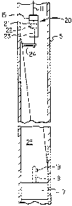
Figure 1 shows a conventional electric wireline
unit setup for setting a packer anchor in a wellbore.
Figure 2 shows one embodiment of apparatus
useful in this invention which employs an electric wireline
setting tool.
Figure 1 shows the earth 1 having a wellbore 2
extending downwardly thereinto. Wellbore 2 is lined with
surface casing 3 to a fixed depth 4. Wellbore 2 further
contains casing 5 which extends from conventional wellhead
2
A~IIEf'JDED SHEET
iPEA/FP

21~21~5
DP 50-6-1512A
6 at earth's surface 7 down to a producing formation (not
shown). Casing 5 extends into wellhead 6 which is
surmounted by a conventional crown valve 8. Wellhead 6
carries valued conduit 9 from which oil, gas or other
fluids produced from the producing formation pierced by
casing 5 can be removed from the wellbore for treatment,
storage, transportation, and the like.
Located on earth's surface 7 adjacent wellhead
6 is a conventional electric wireline unit 10 which carries
a supply of electric wireline 11. Wellhead 6 is surmounted
by a conventional lubricator 12 which carries a sheave
wheel 13 over which wireline 11 passes when it enters
lubricator 12 by way of stuffing box grease injector head
or 14 for entry into the interior of wellbore 2 and casing
5.
In Figure 1, wireline 11 is shown to be
carrying a conventional cable head 15 which simply provides
a connecting function for whatever apparatus is to be
connected to and carried by wireline 11. Below cable head
15 there is provided a conventional electric wireline
setting tool 16. Setting tool 16 carries a whipstock
packer or packer-anchor 17. Packer 17 has rigidly fixed
thereto upstanding stinger 18, stinger 18 being fixed to
setting tool 16 in a conventional manner. Stinger 18 also
carries orienting lug 19 for orienting the whipstock in the
desired manner when the whipstock is set onto packer 17.
Packer 17 can also be set with a single arm bow spring,
magnet or similar orientation device plus a surface read
out device to tell the operator if lug 19 is in a desirable
position.
When packer 17 is lowered to the desired
location along the length of casing 5, setting tool 16 is
electrically actuated from wireline unit 10 by transmission
of an electrical signal along wireline 11 to sever setting
tool 16 from stinger 18 in a conventional manner. Setting
tool 16 can be any basic wireline setting tool such as a
3
.v"~~ =~~D~~? ~s~=,~.~-
~. ~.;':~.~ H

DP 50-6-1512A
Baker Model E-4 wireline pressure setting device. The
anchor can then be checked with a conventional survey tool
to determine the orientation of lug 19. The method, as
thus far described, is known to the prior art and need not
be described in greater detail to fully inform those
skilled in the art.
After packer 17 is set inside casing 5 in the
manner described in Figure 1, it is time to set a whipstock
onto packer 17. In accordance with one embodiment of this
invention, as shown in Figure 2, wireline 11 and cable head
15 are employed to carry an electric wireline setting tool
20 which carries a conventional firing head 21 similar to
that used in setting tool 16. Setting tool 20 also carries
piston 22 which moves downwardly, in the case of the
apparatus of Figure 2, in response to the detonation of
explosive carried in firing head 21. The explosive is
detonated by means of an electrical signal passed through
wireline 11 from electric wireline unit 10 of Figure 1.
Piston 22 carries piston rod 23 which is connected directly
or indirectly to a shear member 24 or connecting device
such as shown in U.S. Patent 5,222,554 to Blount et al.
Shear member 24 is rigidly fixed to whipstock 25. Thus,
when whipstock 25 is set down onto anchor 17 so that
stinger 18 and orienting lug 19 mate with matching
apertures and grooves in the interior of whipstock 25, it
is time to separate setting tool 20 from whipstock 25.
This is done by electrically actuating the explosive in
firing head 21 which imparts an impact force to piston 22
which force severs shear member 24 or otherwise releases
whipstock 25. Thereafter, wireline 11, cable head 15 and
setting tool 20, along with piston 22 and rod 23, can be
removed from the interior of casing 5, thereby leaving
whipstock 25 set firmly onto packer 17. It should be
understood that other tools can be used such as those in
which piston 22 does not move but rather the cylinder
around the piston or some other member move to effect the
4
'r'~y:_'ljrl~- ' !.-
'. .. '".J .. . _ ~ J.-~
n. j": ~.. ,. . ._ /

DP 50-6-1512A
desired shearing action.
Optionally, a conventional orienting tool
can be carried by the setting assembly 20 of Figure 2. The
orienting tool is used to tell the operator at the earth's
surface the orientation of the whipstock while it is being
set in place on packer 17.
A conventional indexing tool can also be
carried by setting assembly 20. This tool is used to
physically rotate the whipstock and orient it in the
desired direction before it is set onto packer 17.
The apparatus of this invention can be employed
inside any well conduit in a wellbore and can be run
through tubing that is already in place inside casing such
as casing 5. In the case of through tubing operations the
tubing can end intermediate the length of the casing so
that the anchor packer and whipstock can be passed through
the tubing and then set inside the casing below where the
tubing ends.
Reasonable variations and modifications are
possible within the scope of this disclosure without
departing from the spirit and scope of this invention.
AME(VDED SHEET
~~'EA/E.P

Dessin représentatif
Une figure unique qui représente un dessin illustrant l'invention.
États administratifs

2024-08-01 : Dans le cadre de la transition vers les Brevets de nouvelle génération (BNG), la base de données sur les brevets canadiens (BDBC) contient désormais un Historique d'événement plus détaillé, qui reproduit le Journal des événements de notre nouvelle solution interne.

Veuillez noter que les événements débutant par « Inactive : » se réfèrent à des événements qui ne sont plus utilisés dans notre nouvelle solution interne.

Pour une meilleure compréhension de l'état de la demande ou brevet qui figure sur cette page, la rubrique Mise en garde , et les descriptions de Brevet , Historique d'événement , Taxes périodiques et Historique des paiements devraient être consultées.

Historique d'événement

Description Date
Inactive : Périmé (brevet - nouvelle loi) 2015-05-25
Lettre envoyée 2004-05-27
Inactive : Lettre officielle 2004-02-10
Accordé par délivrance 2001-07-24
Inactive : Page couverture publiée 2001-07-23
Inactive : Inventeur supprimé 2001-05-16
Inactive : Taxe finale reçue 2001-04-10
Préoctroi 2001-04-10
Lettre envoyée 2000-10-13
Un avis d'acceptation est envoyé 2000-10-13
Inactive : Approuvée aux fins d'acceptation (AFA) 2000-09-28
Inactive : Acc. réc. RE - Pas de dem. doc. d'antériorité 1997-09-04
Inactive : Renseign. sur l'état - Complets dès date d'ent. journ. 1997-08-28
Inactive : Dem. traitée sur TS dès date d'ent. journal 1997-08-28
Toutes les exigences pour l'examen - jugée conforme 1997-06-05
Exigences pour une requête d'examen - jugée conforme 1997-06-05
Demande publiée (accessible au public) 1995-12-14

Historique d'abandonnement

Il n'y a pas d'historique d'abandonnement

Taxes périodiques

Le dernier paiement a été reçu le 2001-04-25

Avis : Si le paiement en totalité n'a pas été reçu au plus tard à la date indiquée, une taxe supplémentaire peut être imposée, soit une des taxes suivantes :

  • taxe de rétablissement ;
  • taxe pour paiement en souffrance ; ou
  • taxe additionnelle pour le renversement d'une péremption réputée.

Les taxes sur les brevets sont ajustées au 1er janvier de chaque année. Les montants ci-dessus sont les montants actuels s'ils sont reçus au plus tard le 31 décembre de l'année en cours.
Veuillez vous référer à la page web des taxes sur les brevets de l'OPIC pour voir tous les montants actuels des taxes.

Titulaires au dossier

Les titulaires actuels et antérieures au dossier sont affichés en ordre alphabétique.

Titulaires actuels au dossier
PHILLIPS PETROLEUM COMPANY
ATLANTIC RICHFIELD COMPANY
CHARLES D. HAILEY
Titulaires antérieures au dossier
CHARLES M. HIGHTOWER
CURTIS G. BLOUNT
Les propriétaires antérieurs qui ne figurent pas dans la liste des « Propriétaires au dossier » apparaîtront dans d'autres documents au dossier.
Documents

Pour visionner les fichiers sélectionnés, entrer le code reCAPTCHA :


Pour visualiser une image, cliquer sur un lien dans la colonne description du document. Pour télécharger l'image (les images), cliquer l'une ou plusieurs cases à cocher dans la première colonne et ensuite cliquer sur le bouton "Télécharger sélection en format PDF (archive Zip)" ou le bouton "Télécharger sélection (en un fichier PDF fusionné)".

Liste des documents de brevet publiés et non publiés sur la BDBC .

Si vous avez des difficultés à accéder au contenu, veuillez communiquer avec le Centre de services à la clientèle au 1-866-997-1936, ou envoyer un courriel au Centre de service à la clientèle de l'OPIC.


Description du
Document 
Date
(aaaa-mm-jj) 
Nombre de pages   Taille de l'image (Ko) 
Dessin représentatif 1997-12-30 1 5
Dessin représentatif 2001-07-11 1 4
Abrégé 1995-12-13 1 40
Revendications 1995-12-13 1 33
Description 1995-12-13 5 218
Dessins 1995-12-13 1 28
Revendications 1997-10-20 1 34
Description 1997-10-20 5 223
Abrégé 2001-07-22 1 40
Dessins 2001-07-22 1 28
Accusé de réception de la requête d'examen 1997-09-03 1 173
Avis du commissaire - Demande jugée acceptable 2000-10-12 1 163
Correspondance 2001-04-09 1 51
PCT 1996-12-04 15 554
Correspondance 2004-02-09 1 10
Taxes 1996-12-04 1 50