Note : Les descriptions sont présentées dans la langue officielle dans laquelle elles ont été soumises.
2192504
- 1 -
PLASTIC FENCING AND COMPONENTS THEREFOR
FIELD OF THE INVENTION
This invention relates to plastic fencing and components therefor.
More particularly, the invention relates to the provision of decorative or
ornamental maintenance free fencing utilizing plastic components which can
be easily and quickly erected using simple tools, will be strong and durable,
impervious to rot, corrosion, insects, and weathering thereby maintaining its
ascetic appearance indefinitely.
Further the invention relates to fencing as aforesaid which will
enable the direction of the fence line to be readily changed over a wide range
of angles.
Still further the invention relates to fencing as aforesaid which can
be readily dismantled to replace individual members or entire fence sections
2 o without affecting adjoining sections.
BACKGROUND OF THE INVENTION
2 5 Plastic fences have been known for some considerable time but so
far have not been widely accepted for various reasons including their lack of
ascetic appeal, cost, difficulty of erection or disassembly, difficulty in
replacing
individual fence members such as the fence rails or removal or replacement of
fence sections.
U.S. Patent 3,554,494, granted January 12th, 1971, discloses an
arrangement wherein the posts and rails are formed as rectangular hollow
plastic extrusions with a series of internal compartments into which wood or
metal reinforcing members can be inserted. The rails are secured to the faces
2192~0~
- 2 -
of the posts by screws which remain exposed to provide a fence which lacks
ascetic appeal.
Other plastic fencing involves slotting rectangular or square posts
and inserting the ends of rail members into the post slots as shown by U.S.
Patent 3,955,801, granted May 11th, 1976, U.S. Patent 4,477,058, granted
October 16th, 1984, U.S. Patent 4,722,514, granted February 2nd, 1988, and
U.S. Patent 5,161,783, granted November 20th, 1992. With such
arrangements, erecting the fence is very awkward as either the posts cannot
be set up first or have to be set up at very critical spacing to enable the
juggling of the rail members into the slots, and either the rail members
cannot
be removed or cannot be removed without affecting adjoining sections of the
fence and the fence sections can only extend from the slotted faces of the
posts and are limited to inline fencing or fencing forming a right angle.
SUMMARY OF THE INVENTION
According to one aspect of the present invention, the fence rails are
2 0 secured to a face of the posts inline with the post centers by a concealed
connection that can be made after the posts have been installed and the rails
can be disconnected from the posts without affecting the posts or the rails of
any other section of the fencing.
2 5 In another aspect, the rail to post connections provide for effective
rail length adjustments to accommodate inaccuracies in the spacing of the
posts.
The posts according to the preferred form of the invention have an
3 0 octagonal shape so that in addition to inline fencing adjoining fence
sections
can be oriented at angles of 45°, 90° and 135° either
side of an inline position.
More particularly, according to the preferred form of the invention,
the rail to post connection comprises an hanger fitted to a selected face of
the
219250
- 3 -
post and a plastic bracket having a first end having a hood portion for
overlying and concealing said hanger with means within said hood portion for
interlockingly engaging with said hanger to secure said first end in abutting
relation with the post, and a second end in the form of a sleeve to
telescopically receive the rail end.
In accordance with another aspect of the invention, the vertical
fence slats or pickets carried by the rails are attached thereto by concealed
connections to enhance the ascetic appearance of the fence.
Further, according to the invention, the rails and pickets are formed
as hollow extrusions formed to accept reinforcing members such as metal
channels and the like where desired for increasing strength and holding
power for fasteners used to connect the fence members together.
In another aspect of the invention, the frame members are adapted
to be extruded utilizing a core of reprocessed thermoplastic material having
the exposed surfaces thereof covered with a protective cap stock to protect
against weathering, impact and the like and to impart color if desired.
Still another aspect of the invention is the provision of top closures
for closing the open upper ends of the posts and slats or pickets which can be
easily and quickly mounted in place and positively secured against accidental
removal.
In this connection, the invention further provides a novel cap for
the octagonal posts formed of two identical mating half sections which mate
together and snap lock with the top of the post.
3 0 These and other features and advantages will be apparent from the
following detailed description taken in conjunction with the accompanying
drawings.
~1~25~~~
- 4 -
BRIEF DESCRIPTION OF THE DRAWBVGS
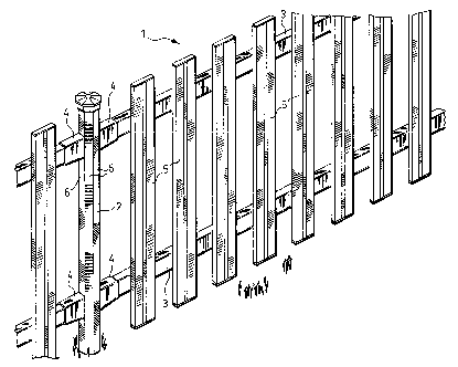
Figure 1 is a broken away perspective view of a fence embodying
the invention.
Figure 2 is an exploded perspective view of a post fitted with
hangers ready to receive a bracket member for connecting a fence rail to the
post in a concealed connection.
Figure 3 is a broken away perspective view of a post with a rail
bracket attached and showing the fence rail about to be inserted into the
bracket with the post about to be capped.
Figure 4 is a perspective view looking down at the front of the rail
support bracket.
Figure 5 is a perspective view looking at the rear of the fence
bracket from the underside of the bracket.
2 0 Figure 6 is a sectional view on the line 6-6 of Figure 5 of the
bracket.
Figure 7 is a broken away vertical sectional view illustrating the
attachment of one of the rails to one of the posts via the post hanger and
rail
2 5 bracket.
Figure 8 is a broken away perspective view of one of the fence
uprights or slats showing it about to receive a reinforcing channel insert.
3 0 Figure 9 is a perspective view of the slat of Figure 8 about to be
secured to one of the fence rails.
2192~0~
- 5 -
Figure 10 is a view similar to Figure 9 but showing the slat about
the receive a closure cap giving the slat a pointed picket appearance and
about to receive a closure to conceal the fastening means.
Figure 11 is a horizontal sectional view showing the slat connected
to the rail.
Figure 12 is a plan view of the slat and rail indicating how the
depending portion of the cap shown in section is secured to the slat.
Figure 13 is a broken away perspective view of a slightly modified
form of slat showing it about to receive a flat closure or cap.
Figure 14 is a view of the slat of Figure 13 with the cap secured in
place and the slat about to be closed to conceal the fastening means.
Figure 15 is a view similar to Figure 13 showing a slightly modified
arrangement for fastening the cap or closure to the slat.
2 0 Figure 16 is a broken away perspective view of a post having a
decorative cap or closure.
Figure 17 is an enlarged exploded perspective view of the upper
end of the post and cap with the cap half sections about to be connected prior
2 5 to snap fitting over the upper end of the post.
Figure 18 is a perspective view of the post closure or cap as shown
in Figure 3.
3 0 Figure 19 is a broken away perspective view of an alternative
arrangement of rails and slats in which the slats are in line with and
inserted
into the rails.
219250:
- 6 -
DETAILED DESCRIPTION ACCORDING TO THE PREFERRED
EMBODIMENTS OF THE PRESENT INVENTION
With reference to Figure 1, the fence generally designated at 1 is
erected from plastic members comprising posts 2, rails 3 supported from the
posts by brackets 4, and uprights or slats 5 secured to the rails as
hereinafter
more fully described.
Although only one post is shown, it will be understood that posts
will be set up at the requisite spacing for each fence section and the rails
will
have the appropriate length as hereinafter more fully described to span
between the support brackets 4 carried by the posts.
As shown in Figure 2, each of the posts 2 is hollow and in its
preferred form is of octagonal cross section presenting eight flat exterior
vertical mounting faces 6 so that the fence rails can be secured thereto at
angles of 45° and multiples of 45° so that the rails of
adjoining fence sections
can be relatively oriented in eight different directions.
2 0 The posts 2 are preferably extruded to provide a polyvinyl core 7
coated on the exterior thereof by a protective cap stock designated by the
dotted lines 8 containing suitable agents to protect against ultra violet
radiation, provide impact resistance, coloring agents, and the like.
2 5 The cap stock also provides a smooth clean exterior surface to the
post allowing the core 7 to be extruded utilizing material containing
reprocessed thermoplastics.
Adjacent its top, the post 2 is provided with short horizontal slots 9
3 0 on the faces 6 which are in 90° relation. These slots are for the
attachment of
the post caps or closures such as the cap 10 shown in Figure 1 as hereinafter
more fully described.
CA 02192504 2004-05-21
As shown in Figure 2, the means for securing each of the rail
supporting brackets 4 comprises a hanger generally designated at 11 which i s
preferably formed of metal although it may be made of plastic, has a wide thin
planar panel, plate or tongue portion 12 carried by legs 13 formed by material
bent out of the plane of the plate 12 and extending at right angles thereto
and
terminating in outwardly turned mounting feet 14.
With this arrangement, each of the hangers 11 can be mounted to a
selective one of the post faces 6 by suitable screws 1 S to which access is
afforded through the notches 16 formed in the plate 12 by the formation of the
legs 13 and feet 14.
Adjacent its lower end, the plate 12 has a central raised locating boss
27.
When the hanger 11 is mounted to the face 6 of the post, the thin
planar plate 12 stands proud of the post ready to have the rail supporting
bracket 4 slid into engagement therewith for securing the bracket in butting
relation with the respective post face 6.
As will be seen particularly in Figures 2 and 4, the forward end of
the bracket 4 which is adapted to abut the face 6 of the post is in the form
of a
hood 17 open to the bottom of the bracket having side walls 18 and a top wall
19.
This hood portion 17 of the bracket extends rearwardly into the
bracket to a partition wall 20.
Rearwardly of the partition wall the bracket is in the form of a sleeve
3 0 21 as will be seen from Figures 5 and 6 the sleeve being configured to the
shape of the rails 3 with the mouth 22 of the sleeve being slightly larger
than
the dimensions of the rails so that an end of the rail can be telescopically
received within the sleeve.
2192~9~.
_8_
Provided within the hood portion 17 of the bracket is a pair of
inwardly projecting legs 23 which define with the partition wall 20 spaced
slots 24 which are adapted to receive the thin locking hanger plate 12 when
the bracket 4 is slid down the post face 6 so that the plate 12 is secured
between the legs 23 and partition wall 20 of the bracket with the forward
edges 25 of the bracket which are preferably chamfered as at 26 in butting
engagement with the post face.
The protruding plate boss 27 riding on the partition wall 20 as the
bracket is being slid down the post face causes a tight friction fit between
the
plate and bracket causing a slight bowing of the plate outwardly between the
opposing legs 23.
The partition wall 20 adjacent the bottom thereof is provided with a
small indentation 28 adapted to receive the plate boss 27 when the bracket is
slid fully home at which time the resiliency of the bracket plate 12 causes
the
plate boss 27 to snap into the recess 28 to indicate final location. The
arrangement is such however that the rounded surfaces of the boss and recess
27 and 28 allow the bracket to be forced upwardly for removal with the boss
2 0 camming out of the recess.
The bracket 4 is preferably made of a weatherable PVC containing
appropriate ultra violet protecting agents and the like and may be colored if
desired.
It will be appreciated that the fence posts will be erected at the
desired spacing and the hangers 11 secured to opposing fence post faces 6
and then the rails 3 will have each end telescoped into a bracket 4 as
illustrated in Figure 7 and the bracket slid down the post face 6 until it is
fully
3 0 home with the plate boss 27 seated in the bracket in the indentation 28.
Because of the telescopic relation between the rail and the supporting
brackets, it will be understood that the spacing of the posts does not have to
be precisely accurate as the telescoped rail ends can adjust within the
bracket
sleeves 21.
2192~0~
_ g
As in the case of the posts, preferably the rails 3 comprise hollow
co-extrusions of a PVC core 29 which may contain reprocessed plastic
material and a cap stock indicated by the dotted lines 30. For strength the
rails may contain a reinforcing insert such as the channel 31 shown in Figure
3.
It will also be understood that in mounting the rails as illustrated in
Figure 3 the bracket 4 at one end may first be slid into secured butting
relation
with the post face and then one end of the rail with its reinforcing insert
31,
where used, inserted into the sleeve portion 21 of the bracket. The other end
of the rail may then be inserted into its respective bracket and the bracket
at
such other end slid into secured position with its respective hanger.
The uprights or slats 5 shown in Figure 1 are illustrated in detail in
Figures 13 and 14.
Each of these uprights comprises a longitudinal extrusion
presenting two spaced main rectangular sleeve or tubular sections 32 joined
2 0 by a smaller rectangular sleeve or tubular section 33 with the sleeve
sections
having a common rear wall 34 providing a channel 35 between the front faces
36 of the sleeve or tubular sections 32.
Grooves 37 provided adjacent the entrance of the channel 35
provide a locking means for a closure strip 38 shown in Figure 14 provided
with inturned legs 39 carrying projecting ribs 40 adapted to snap into the
grooves 37.
Again these uprights or slats 5 are preferably a coextrusion of a core
3 0 41 of PVC material which may contain reprocessed plastic material and a
cap
stock indicated by the dotted line 42.
The central sleeve or tubular section 33 may contain a suitable
reinforcing insert such as a steel or aluminum channel as desired.
2192~0~
- 10 -
The closure or cap 43 for closing the open upper end of the slat 5 is
provided with depending guide legs 44 at the corners thereof adapted to fit
snugly within the outer sleeve sections 32. The cap also has a central
depending tongue 45 of channel form which is adapted to seat against the
bottom wall 46 of the channel in position to receive a retaining screw 47 to
secure the cap against dislodgement accidentally or through tampering.
It will be understood that the slat 5 will be secured to the rail 3 by
fasteners (not shown) located within the front channel 35 so that when the
closure strip 38 is snapped into position to close the channel it will hide
both
the retaining screw 47 and the fasteners used to secure the slat to the rails.
Figure 15 shows the slat 5 with a slot 48 in the bottom wall 46 of
the channel 35 to receive and interengage with a depending hooked leg 49 of
a slightly modified cap 43' to retain the cap against accidental removal.
The upright or slat 50 shown in Figures 8 to 12 is similar to the slats
5 but of increased thickness for added strength.
Again the slat 50 has two main rectangular tubular or sleeved
sections 51 spaced apart by a smaller or secondary rectangular tubular or
sleeved section 52 having a common rear wall 53 providing a central channel
54 extending inwardly from the front faces 55 of the tubular or sleeved
2 5 sections 51.
Adjacent the entrance to the channel 54 are grooves 56 for
securing a closure strip 57 as shown in Figures 10 and 12 which is provided
with inturned legs 58 having ribs 59 adapted to snap into the grooves 56.
The secondary or central tubular section 52 of the slat 50 is adapted
to receive a reinforcing insert such as the channel 60 of suitable material
such
as aluminum or steel to assist in the holding power of the fasteners or screws
such as illustrated at 61 in Figure 9 which secure the upright or slat to the
rail
2192~0~~
- 11 -
3 the screw penetrating the reinforcing insert 60 of the slat as well as the
plastic of the slat, the plastic of the rail 3, and the reinforcing insert 31
of the
rail where used.
To assist in locating the position of the screw 61, the bottom wall 62
of the channel 54 is shown provided with a central guide groove 63.
While Figures 13 to 15 showed the use of a flat closure or cap 43,
43', Figure 10 illustrates a cap or closure 64 in the form of a narrow
truncated
pyramid to give the fence slat or upright the appearance of a pointed picket.
Again, the cap or closure 64 has depending locating legs 65 at the
corners thereof to fit down into the main sleeve sections 51 with a snug fit
to
orient the cap and a channel shaped depending tongue portion 66 adapted to
abut the bottom wall 62 of the channel 54 to be secured thereto by a fastener
or screw 67. Again, after securement of the upright to the fence rails and
attachment of the cap 64, the closure strip 57 is snapped into position to
hide
the fasteners 61 and 67.
2 o As in the case of the uprights or slats 5, the uprights or slats 50 are
preferably a coextrusion as discussed with respect to slats 5.
The post cap or top closure 10 shown in Figures l, 3 and 7 is
particularly illustrated in Figure 18 which shows the short inwardly
projecting
teeth 68 located adjacent the bottom of the hexagonal wall 69 in 90°
spaced
relation so that when the hexagonal wall 69 of the cap is fitted down over the
upper end of the post 2 with the locking teeth 68 registering with the post
slots 9 these teeth will snap into and interlock with the post slots as
illustrated
in Figure 7.
Figures 16 and 17 illustrate an alternative decorative cap or closure
70 for closing the upper end of the post 2.
2192~~1
- 12 -
In this case, the cap or closure comprises two identical half sections
71 each having a half hexagonal base wall 72 supporting a half of an eight
sided pointed or spear head dome portion 73 having arcuate wall segments 74
arching upwardly and inwardly to a top point 75 from a half hexagonal base
76 connected to the base 72 by inwardly arched walls 77.
Each of the half sections 71 is provided internally on one side with
projecting locking legs 78 and on the other side with locking leg receiving
loops 79 so that when the identical half sections are arranged in face to face
relation as illustrated in Figure 17 the locking legs 78 will register with
the
locking loop 79 allowing the two half sections to be snapped together to
complete the cap or closure 70.
The cap in its fastened condition can then be placed down over the
top of the post 2 again being provided with locking teeth 80 adjacent the
bottom of the base wall 72 to snap into the post slots 9.
Figure 18 illustrates a modified form of rail and slat arrangement
wherein the slats 81 and 82 are inserted into slots 83 and 84 respectively in
2 0 the rails 85 so that the slats or uprights are located centrally of the
rails.
The slats and rails are formed of suitable extrusions as aforesaid and
it will be understood that the rails will be connected to the posts in the
same
manner as described with respect to the rails 3 and illustrated in Figures 2,
3
2 5 and 7.
In all instances, provision is made so that no fasteners connecting
the uprights to the rails are exposed and the connection between the rails and
the posts are concealed.
With the provision of the hexagonal posts, the rails can be oriented
in eight different directions in 45° angle increments so that the
fencing is not
restricted to simple inline fences or fences at right angles.
2mz5o~
- 13 -
In addition, a fence section may readily be removed by sliding the
rail supporting brackets 4 upwardly to clear the hangers 11 without in any
way affecting adjoining fence sections. The ability to remove fence sections
to allow, for example, the passage of a vehicle into the fenced area provides
an
important benefit. Also, of course, the individual uprights or slats 5 and 50
can be quickly individually removed and replaced as required.
With the fence structure shown in Figure 18, it will be understood
that the rails 85 can be readily disconnected from the posts for replacement
of
the slats 81 and 82 or replacement of the rails themselves.
Because of the hollow construction of the rails and slats, they are all
capable of taking inserts in the form of metal tubes or channels or other
shaped inserts wherever desired. It will also be understood that, while the
invention in its preferred form employs hexagonal posts 2, the rail to post
connection afforded by the brackets 4 and hangers 11 is applicable to posts of
other cross section.
It will be understood that various other modifications may be made
2 0 to the fence components without departing from the spirit of the appended
claims.