Note : Les descriptions sont présentées dans la langue officielle dans laquelle elles ont été soumises.
4-4798d/8026-45/Case #35
2 ~ 9 2as~
FORCED AIR VENT FOR A ROOF EAVE
BACKGROUND OF THE INVENTION
The present invention relates in general to forced air
exhaust and venting arrangements for ducting exhaust air
from the interior to the exterior of a structure. More
specifically the present invention relates to a forced air
vent for a roof cave which is designed to accommodate the
removal of exhaust air from a clothes dryer or exhaust fan.
a2-~ere are a number of home installation arrangements
whers clothes dryer exhaust cannot be vented through a wall
R:o tize exterior of the home. This problem also exists in a
number of homes with regard to the venting of bathroom fans
and other exhaust fans. In order to address this problem,
the most typical approach is to route the corresponding
exhaust ducting up into and through the attic spaca of the
home. However, under applicable building codes, the exhaust
air cannot be expelled into the attic spacA but must be
expelied to the outside atmosphere.
In order to comply with the applicable building codes,
one option is to go up and through the roof, using some type
of existing roof cap. This approach creates the potential
for rain water to leak into the attic space from the area of
the roof cap. Accordingly, this option is seen to be less
than preferred.
,mother option is to route the exhaust air to the area
of the roof cave. Since this area is protected from rain,
it avoids the primary problem associated with a roof exit
location. At the present time, the typical approach i.s to
prepare an opening in the roof cave and bring the exhaust
ducting to that location. A screen mesh or open louver vent
is then used to cover the roof cave opening,
219272
-2-
While the rainwater problem is eliminated with. the roof
eave location, this particular arrangement allows outside
air, particularly cold air, to enter the ducting and travel
into the house to the location of the clothes dryer, exhaust
fan, vent, or exhaust port. In the reverse direction, hot
air which is being used to heat the house is freely escaping
through the roof eave opening.
In order to utilize the roof eave location and avoid or
eliminate the aforementioned problems, the present invention
was conceived. The present invention creates a blocking
baffle plate arrangement as part of a vent cahich blocks th~~
incoming flow of air and yet permits the escape of exhaust
air. Since some degree of forced air flow is required in
order to open the baffle plates, hot heating air within the
house cannot freely escape to the outside atmosphere. The
presence of grid-like grate panels on the ends or the
present invention vent make it impossible for birds to nESt
inside the vent.
CA 02192762 1999-08-30
3
SUMMARY OF THE INVENTION
A forced air vent for use in connection with the removal~of
exhaust air from a structure according to one embodiment of the
present invention comprises a main body, an interior space
defined by the main body, and a pair of baffle plates. The main
body includes a perforate bottom wall and a pair of oppositely
disposed side walls. The pair of baffle plates are hingedly
connected to the main body and are outwardly and upwardly
movable with respect to the center of the vent in response to
receipt of a positive air pressure.
One object of the present invention is to provide an
improved forced air vent.
In accordance with the present invention, there is provided
an air vent for controlling the air flow into and out of a
structure, said air vent comprising: a main body including
perforate bottom wall and a pair of oppositely disposed side
walls which are positioned along said bottom wall so as to
define therewith an interior space, said bottom wall having a
solid central portion and an open grate distal portion, said
solid central portion having a concave exterior surface and a
convex interior surface protruding into said interior space and
said distal portion and an open grate distal portion, said solid
central portion having a convex exterior surface protruding
outwardly of said interior space; an a movable baffle plate
disposed within said interior space for controlling the flow of
air through said air vent and said baffle plate being hingedly
connected to said main body of said air vent.
In accordance with the present invention, there is further
provided an air vent comprising: a main body including a bottom
wall and a pair of enclosing side walls, said bottom wall being
shaded with two open end portions and a solid central panel,
each of said open end portions being separated from said solid
central panel by a corresponding abutment ledge; and a pair of
CA 02192762 1999-08-30
' 3a
movable baffle plates hingedly connected to said main body and
positioned to control the flow of air through said open end
portions, wherein each open end portion is constructed and
arranged with a convex grate panel.
In accordance with the present invention, there is further
provided an air vent comprising: a main body including a bottom
wall and a pair of enclosing side walls, said bottom wall being
shaded with two open end portions and a solid central panel,
each of said open end portions being separated from said solid
central panel by a corresponding abutment ledge; and a pair of
movable baffle plate hingedly connected to said main body and
positioned to control the flow of air through said open end
portions, wherein said solid central panel of said bottom wall
having a convex curvature protruding into said interior space.
In accordance with the present invention, there is further
provided an air vent comprising: a main body including a bottom
wall and a pair of enclosing side walls, said bottom wall being
shaped with two open end portion and a solid central panel, each
of said open end portions being separated from said solid
central panel by a corresponding abutment ledge; and a pair of
movable baffle plates hingedly connected to said main body and
positioned to control the flow of air through said open end
portions, wherein said solid central panel of said bottom wall
having a convex surface protruding into said interior space and
each of said open end portions of said bottom wall having a
convex curvature protruding out from said interior space.
In accordance with the present invention, there is further
provided an air vent comprising; a main body including a
perforate bottom wall and a pair of oppositely disposed side
walls, said pair of side walls positioned along said bottom wall
to define an interior space, said bottom wall having a central
portion and a plurality of distal portions, said central portion
having a concave curvature and each of said distal portions
CA 02192762 1999-08-30
3b
including a grate panel: and a plurality of movable baffle
plates hingedly connected to said main body, each of said
plurality of movable baffle plates being constructed and
arranged to control the flow of air through the corresponding
grate panel, wherein each of said plurality of distal portions
has a convex curvature.
Related objects and advantages of the present invention
will be apparent from the following description.
2'92762
-4-
BRIEF DESCRIPTION OF THE DRAWINGS
FIG. 1 is a fragmentary, side elevational view of forced
air vent according to a typical embodiment of the present
invention as installed through a roof eave of a structure.
FIG. 2 is a perspective view of the main body of the
FIG. 1 forced air vent.
FIG. 3 is an exploded, perspective view of the FIG. 1
forced air vent showing the location of two baffle plates
according to the present invention.
FIG. 4 is a perspective view of the FIG. 1 forced air
vent with the baffle plates pivoted into an open-to-air-flow
position.
FIG. 5 is a perspective view of the FIG. 1 forced air
vent with the baffle plates pivoted into a
closed-to-air-flow position.
~~ 2'~ 9 2762
-5-
DESCRIPTION OF THE PREFERRED EMBODIMENT
roc the purposes of promoting an understanding of the
principles of the invention, reference will now be made to
tae embodiment illustrated in the drawings and specific
language will be used to describe the same. It will
nevertheless be understood that no limitation of the scope
of the invention is thereby intended, s~_~ch alterations and
further modifications in the illustrated device, and such
further applications of the principles of the invention as
illustrated therein being contemplated as would normally
occur to one skilled in the art to which the invention
Lelates.
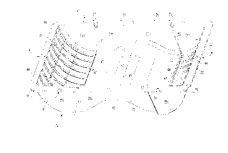
Referring to FIG. 1, there is illustrated an air vent 20
for a roof eave 21 according to the present invention. Air
vent 20 includes a unitary, molded main body 22 and a pair
of movable baffle plates 23 and 24. The roof eave 21
inc7_udes an air flow opening 25 in order to permit air flow
between forced air' 3ucting 26 and the outside atmosphere
27. Ducting 26 is representative of the type of conduit
used to route dryer exhaust out of the structure.
Alternatively ducting 26 could extend from an exhaust fan,
vent, or exhaust port within the structure. Vent 20 is
designed with the two baffle plates 23 and 24 in order to
control the air flow through vent 20 and limit the flow to
only an exiting flow.
vent 20 allows exhaust air from within the structure to
escape to the atmosphere 27 while not allowing outside
atmospheric air to enter the ducting 26 by way o~ opening
25. Moisture and debris are prevented from either blowing
or flowing through vent 20 by the one-way design
incorporating the two baffle plates 23 and 24. As
illustrated in F'IG. 2, there are other features cf vent 2.0
which help to preclude the in-flow of any de5ris into vent
20. The under-~:.he-eave orientation of vent 20 also
facilitates its operation by utilizing the effect of gravity
2 ~ ~ 262
-6-
to help keep debris and moisture out of vent 20. Gravity
also helps control the movement of baffle plates 23 and 24.
Referring to FIG. 2, the main body 22 is illustrated in
greater detail. Main body 22 includes a bottom wall 30
arranged into three distinct portions 31, 32, and 33, a pair
of oppositely-disposed sidewalls 34 and 35, and an upper,
outcaardly extending peripheral flange 36. The bottom wall
30 in combination with the two sidewalls 34 and 35 defines a
hollow, interior space 37 which is located within main body
22. Flange 36 includes a substantially flat upper surface
39 which is designed to abut up against the outer surface 40
cf Pave 21. Mounting apertures 41 provide clearance far ttue
use of conventional threaded fasteners which are to be
anchored into roof eave 21 in order to secure vent 20 in
position. If an adhesive or caulk is used instead to secure
the vent 20 in position on the roof eave, the mounting
flange 36 can be considered optional since the upper edges
of the two sidewalls 34 and 35 and the upper edges of
portions 31 and 3~ would provide a suitable abutment
surf ace .
Portions 31 and 33 of bottom wall 30 are configured as
smoothly curved (radiused), oppositely-disposed end
portions, each of which extends along an approximate 90
degree arc. The approximate 90 degree arc begins at a
location which generally corresponds to offset edges 42 (and
43) of portion 32 and extends outwardly and upwardly to its
ending location adjacent flange 36. End portions 31 and 33
are sized and shaped in a virtually identical manner so as
to maintain a generally symmetric design to vent 20. A
longitudinal centerline drawn through the approximate center
of vent 20 divides the vent into symmetrical halves which
are located on either side of this geometric centerline with
sidewall 34 on one side of the centerline and sidewall 35 on
the opposite side. Portions 31 and 33 are each designed to
provide an open end portion for main body 22. These open
~~ 2192762
_7_
end portions are then covered by a grate panel in order to
create the perforate appearance for bottom wall 30. With
the unitary construction for main body 22, separate grate
panels do not actually exist, but functionally this is what
is provided. The two grate panels which are integral with
portions 31 and 33 make it impossible for birds to nest
inside of vent 20.
Each end portion 31 and 33 includes a plurality of
substantially rectangular openings 44 which are uniformly
arranged into a row and column pattern. Openings 44 provide
the exit locations for whatever flow passes through opening
25 and into vent 20. As is described hereinafter, the two
baffle plates limit the flow through vent 20 to only one
direction. While air flow is able to leave the ducting 26
by way of opening 25 and flow through vent 20, any reverse
or backflow into vent 20 which could conceivably flow back
into the ducting is blocked by the two baffle plates and the
manner in which those two baffle plates abut up against
abutment edges disposed as part of main body 22.
Center portion 32 is solid throughout and has a curved
contour such that it has a convex inner surface 47 and a
concave outer surface 48 (see FIG. 1). The ends 49 and 50
of portion 32 actually begin to curve in the opposite
direction from the remainder of portion 32. In this way,
the entirety of bottom wall 30 can be viewed from the
outside or. from the exterior as being contoured with a
convex section (portion 31 and end 49) which smoothly
transitions into a concave section (portion 32, including a
small part of ends 49 and 50) which in turn smoothly
transitions into a convex section (portion 33 and end 50).
Each sidewall 34 and 35 is arranged into three distinct
portions 34a, 34b, and 34c (for sidewall 34) and portions
35a, 35b, and 35c (for sidewall 35). While each of the six
sidewall portions are substantially flat and planar,
interface edges 51, 52, 53, and 54 create an offset between
2 ~ 9 ~~6~
-8-
adjacent portions. Portions 34a and 34b are separated by
edge 51 while portions 34b and 34c are separated by edge
52. In a similar manner, portions 35a and 35b are separated
by edge 53 while portions 35b and 35c are separated by edge
54. Coplanar edges 51, 53, and 42 are aligned with each
other such that an imaginary geometric plane which is
co-extensive with each edge is substantially perpendicular
to each of the six portions 34a-34c and 35a-35c. Coplanar
edges 52, 54, and 43 also lie within a corresponding
imaginary geometric plane which is co-extensive with these
three edges and is substantially perpendicular to each of
the six portions 34a-34c and 35a-35c.
Each edge 51 and 53 is inclined and each one extends
outwardly away from portions 34b, 35b, and 32 as it extends
downwardly away from flange 36. A similar edge direction
and incline exists for edges 52 and 54. Accordingly, edges
51 and 52 have a converging orientation in the direction of
flange 36, as do edges 53 and 54. Edges 51, 53, and 42
provide an abutment lip for baffle plate 23 and edges 52,
54, and 43 provide an abutment lip for baffle plate 24 (see
FIG. 3). By shifting the orientation of the baffle plates
23 and 24 off of vertical, as is clear due to the converging
nature of edges 51 and 53 and the converging nature of edges
52 and 54, it is easy for the baffle plates to pivot
upwardly and outwardly in response to the flow of exit air
out through opening 25 and into interior space 37. Equally
important is the fact that the inclined orientation of each
baffle plate 23 and 24 (see FIG. 1) enables gravity to
continue to act on the baffle plates to hold them against
the corresponding edges in order to establish a sealed
interface and preclude any noticeable backflow of air
through vent 20 into opening 25. Vent 20 controls the flow
of air through opening 25 and limits the flow through
opening 25 to one direction (i.e., to only exiting flow).
Disposed in portion 34a is a hinge aperture 57 which is
located adjacent the upper end of edge 51. On the opposite
side (see FIG. 3), an aligned r~inge aperture 58 is located
-- 2 ~i 9 2~fi2
_g_
adjacent the upper end of edge 53. A virtually identical
arrangement exists relative to edges 52 and 54 by means of
hinge apertures 59 and 60. With reference to FIG. 3, it
will be seen that each baffle plate 23 and 24 includes a
substantially rectangular body portion 61 and a pivot or
hinge pin portion 62. Each baffle plate is a unitary,
molded plastic member and is specifically designed to be
light weight and durable. The hinge pin portion 62 includes
a longitudinal axis which coincides with the axis of
rotation for each baffle plate relative to the four hinge
apertures 57-60. The ends of each hinge pin portion 62 of
each baffle plate extend beyond the side edges of the
corresponding body portion of each baffle plate and are thus
able to readily drop down into hinge apertures 57-60. If a
mounting flange 36 is included as part of vent 20, each of
the hinge apertures actually cuts through part of the flange
so that the hinge pin portions can simply be lowered into
position. There is no interlocking arrangement nor any
snap--in design required in order to retain the hinge pin
portions 62 in position in the various hinge apertures
57-60. As will be understood, although the baffle plates
can simply drop down into the various hinge apertures 57-60,
the baffle plates will be held in position when the vent 20
is mounted to the roof eave 21. The outer surface 40 of the
roof eave provides an enclosing member directly against the
open top of the hinge apertures 57-60 so as to securely
retain the four hinge pin portions 62.
Additionally referring to FIGS. 4 and 5, the movement of
baffle plates 23 and 24 relative to main body 22 is
illustrated. When air flow exits ducting 26 and opening 25
(see FIG. 1), it flows downwardly into interior space 37.
In order for the in-coming flow to split somewhat evenly so
as to have two oppositely-directed flow branches, it is
important that vent 20 be installed onto the roof eave 21 in
such a way that vent 20 is geometrically centered in both
~~9~762
-10-
length and width dimensions over opening 25. By centering
vent 20 directly over roof eave opening 25, it is possible
to ensure that the center or apex of convex portion 32 will
be generally centered relative to opening 25. In view of
this relationship and the construction of vent 20, the
in-coming flow out of opening 25 and into interior space 37
branches off or splits into two oppositely-disposed flow
paths, one on each side of the geometric centerline 65 of
portion 32. The convex curvature of portion 32 and the
raised orientation of portion 32 which extends upwardly
toward opening 25 forces each of the two flow paths in a
downward and outward direction. This in turn focuses the
exit flow of each path along and toward the lower edge of
each baffle plate 23 and 24. As should be understood, one
flow branch flows downwardly along the surface of portion 32
and is thus directed at the lower edge of baffle plate 23.
A flow path in the opposite direction extends downwardly
along the surface of portion 32 on the other side of
centerline 65 and is thus directed towards the lower edge of
baffle plate 24. By directing and focusing the flow path of
the exiting air well below the pivoting axis of the hinge
pin portion 62 of each baffle plate, the baffle plates 23
and 24 are able to open more easily and require less air
force in order to pivot to an open condition. If portion 32
is flat throughout (planar), the in-coming flow would not
necessarily be split into two somewhat balanced,
oppositely-disposed flow paths. More importantly, with a
planar center portion 32 there would not be an opportunity
to direct the flow of each branch in the direction of the
lower edge of the corresponding one of the two baffle
plates. If a portion of the exiting flow in each direction
is directed along the pivoting axis line of the
corresponding baffle plate, a much greater force level would
be required due to the cantilever design of the baffle plate
mounting. If more force was required in order to pivot the
baffle plates to an open condition, there is less
2~~2~6~
-11-
likelihood that all of the air which should vent out of the
attic would be permitted to do so. The greater the distance
of separation between the pivoting axis and the impingement
location of the exiting flow against the baffle plate, the
less force required in order to open the baffle plates.
As the two baffle plates pivot upwardly and outwardly
off of their abutment edges, an opening 66 and 67 is created
between the lower edge of each baffle plate and bottom wall
30. These two openings provide flow communication with the
openings 44 in the two grate-like (perforate) end portions
31 and 33.
In the FIG. 4 illustration, the baffle plates 23 and 24
are in an open condition which is created by an exiting flow
of air from opening 25. When the existing flow of air is
removed, gravity returns the two baffle plates 23 and 24 to
a closed condition against their corresponding abutment
edges as it illustrated in FIG. 5. There are of course
numerous positions in between the two extremes of FIG. 4 and
FIG. 5. Depending on the force of air exiting through
opening 25, and depending on the weight of the baffle
plates, the baffle plates which assume a corresponding
orientation between a closed condition and a fully open
condition. However, by focusing and directing the exiting
air along the lower edge of the baffle plates, virtually any
degree of forced air flow exiting from ducting 26 will
achieve some degree of opening to the two baffle plates.
In the closed condition of FIG. 5, any back flow of air
into end portions 31 and 33 will push against the baffle
plates which simply increases the abutment force against tile
abutment edges 42, 43, 51, 52, 53, and 54. By sizing the
two baffle plates to fit closely to portions 34a, 34c, 35a,
and 35c, there is effectively no pathway open that would
admit any backflow of air into opening 25.
While the invention has been illustrated and described
in detail in the drawings and foregoing description, the
~~ 2192~fi~
-12-
same is to be considered as illustrative and not restrictive
in character, it being understood that only the preferred
embodiment has been shown and described and that all changes
and modifications that come within the spirit of the
invention are desired to be protected.