Note : Les descriptions sont présentées dans la langue officielle dans laquelle elles ont été soumises.
JAIV, CI, GUUU 4:4Ut'M SWA~~Y UU1LVY MIL 514 Gba U~~~ 1VU, C4b5 t', 4/lU
AC3'IV'F, MOUNTS FOR AIRCRAFT ENGINES '
Haelc~round and Sux~~~ of the Inv
'This invention relates to the area of active vibration control,
Specifically, the invention relates to improvements in active mounts for fixed
wing
applications. Mote specifically, this invention is directed to a system for
cancelling
two tones which are relative close in frequency, as ins tlae case of the
primary (andlor
secondary) disturbance frequencies of pairs of turbofan or tuboprop engines.
In the realm of active noise and vibration control, there arc three
implementation approaches: active noise control, which uses an inverse-phase
sound
wave to cancel the disturbance signal; active structural control, which
vibrates a
structural component at a frequency to cancel the input disturbance (noise
andlor
vibration); and active isolation control, where an actuator iu a mount is
reciprocated at
the proper frequency, phase and amplitude to cancel the input disturbance
(which,
aga~in~, may be a structural vibration or in the audible range, in which case
it is
experienced as noise). The decoupling feature of the present invention can be
utilized
with each of these three implementation approaches.
Active mounts for controlling vibrational input from an engine to the
5uppo;t 5tructurc axe known_ For example, commonly assigned TJ.$. Patent Np_
5,174,522 issued to Hodgson on December 29, 1992 teaches the use of an active
fluid
mount for vibration cancellation. Systems which actively control vibration or
sound
by using an out of phase cancellation signal are also known and include U.S.
Patent
Nos. 4,677,67b issued 1:o Eriksson on June 34, 1987, 4,153,815 issued to
Chaplin on
May 8, 1979, 4,122,303 issued to Chaplin et al. on October 24, 1978, 4,232,381
isued
to Rennick et al. on November 4, 1980, 4,083,433 issued to Geoh~gat~, Jr. et
al. on
April 11, 1978, 4,878,188 issued to Zeigler, Jr. on October 31, 1989,
4,562,589 issued
to Warnaka et at. on December 31, 1985, 4,473,90 issued to Warnaka ct al. on
September 25, 1984, S,I70,433 issued to Llliott on ~3ecember $, 1992,
4.689.82.1
issued to Salikudden et al. on August 25, 1987, and 5,133,527 issued to Chen
et al. on
July 28, 1992. These systems utilize digital microprocessors (processors) to
control or
minunize mechanical vibration or ambient noise levels at a dc~ned location or
1
CA 02193080 2000-O1-27
' drily, Li. GUUU 'l.4lllra UttriULl VU1LV1 1Y11L ;J1~F GUU UJUJ lvV, G4UJ 1,
JI lU
locations, as for example noise or vibration experienced in an aircra~ cabin
or within
an automobile passenger compartment. Generally, these systems arc responsive
to at
least one external input sisal such as a synchxoz~~ing tachometer signal
and/or error
signal as supplied by verio~ts
la
CA 02193080 2000-O1-27
2193080
W0 95/34769 PCTIU595107474
types of sensors such as microphones, accelerometers, etc. These systems
strive to reduce to zero, or at least minimize, the recurring sound and/or
vibration.
Multiple-input, multiple-output (MIMO) systems are required to '
adequately compensate for the vibrations of plural turbofan or turboprop
engines. In active control systems of the above-mentioned type, it is °
generally required to have an input signal for each tone to be canceled
which is supplied to an adaptive filter and/or a processor which is
indicative of the frequency content and/or amplitude/phase of the input
1Il source, i.e., indicative of the disturbance signal. Particularly, it is
usually
required to have two or more analog or digital waveforms, such as a sine
and cosine wave, that are synchronized with (at the same frequency as) the
input source signal for providing the appropriate information to the
processor and/or adaptive filter. These waveforms will be utilized in
computing the appropriate frequency and amplitude of a cancellation
signal in accordance with a particular algorithm such as least mean
square (LMS) and filtered-x LMS algorithms.
Many such algorithms have difficulty processing two tones which
are close in frequency such as in the case of a right engine operating at a
first frequency NCR and a left engine operating at a second frequency N1L
which is the same or nearly the same as the first frequency. Turbofan and
turboprop engines typically have four tones that are objectionable: N1R
which corresponds to the frequency of the right fan or prop, N'1R which
corresponds to the frequency of the right turbine, N~I,which corresponds to
the left engine fan or prop and N'1L which corresponds to the left engine
turbine frequency. These similar tones (N1R and N1L or N'1R and N'1L) can
cyclicly reinforce one another creating a particularly objectionable beat
frequency. The relative closeness of the two tones can cause the system to
become unstable as the algorithm seeks to find an optimal cancellation
solution.
In practice, each of the error sensors of such a system will pick up
all four of the engine disturbance frequencies, to some degree. The most
general controller objective is for each actuator to provide a cancellation
force at each of the four tones. The controller would provide a signal
segment of sufficient amplitude and phase inverted to cancel each of the
2
drilu, GI, GUUU 4~41fm JrrnDr,t VU1LV1 1V11L ;l14 G00 OJO~ lv~, G4UJ f, U/ lU
individual four components, then superpose the four signal segments into a
single
cancellation signal (complex sine wave) to be fed to the actuator. When any
two of
the four tones are relatively close in frequency (and generally there are two
pairs of
such tones), the control algorithm can have difficulty convdrging to a stable
set of
actuator signals.
'floe pxcscnt i~nventiQn provides decoupling of the response to the two
tones having similarlidentical frequencies by proper positioning of the
sensors and the
actuators. Preferably, both the sensors and actuators can bG placed in the
primary
disturbance path between the power plant (or engine} and the support
structure. (In
the cast of active isolation control, the actuator will necessarily be in the
primary
disturbance path. In the case of active noise cancellation, the microphones
will not be
in the primary disturbance path). In addition, the error sensors must be
widely spaced
enough to prevent cross-coupling of the closely spaced frequencies (N1R and
NFL, for
example). By spatially separating the error sensors, the magnitude of the
signal N»,
detected by the sensors positio~aed to monitor the N,R signal and vice versa,
will be
small enough that it can be ignored (i.c., will be at least an ordcx of
magnitude
smaller) or may be filtered out by the signal conditioner.
In another aspect of the invention, pairs of sets of force transmission
elements within the active mount axe positioned such that each element can
transmit a
vertical fQxce component and a horizontal farce conrlpanent. Further, oxle of
the force
transmission elements from each of the rnvunts is targeted to foealize its
cancellation
farce (i.e., the elastic center, the point at which the axes of force
ir~t~rsect, is at or
beyond the center of gravity of the power plant). Foealization is well known
in the
mounting art, and is more particularly described in U.S. Patents No. 2,175,999
issued
to Taylor and No. 2,241,4Q8 issued in May, 1941 to Lord. Preferably, the two
force
transmission elements are orthogonally oriented, k'urther, in one
errtbodirxxent, each
transmission element is preferably oriented at a 45° angle to the
horizontal. In a
second alternative embodiment, the orthogonal actuators may be arranged to act
along
horizontal vertical axes, respectively. The actuators may be tuned absorbers,
electromagnetic, electrohydraulic of piezoelectric.
3
i 5 2701/2000 Qt6:41 X514 288 8388 Qreceived
CA 02193080 2000-O1-27
CA 02193080 2001-O1-31
Therefore, in accordance with the present invention, there is provided a
system for minimizing vibration transmitted from a plurality of power plants
operating
at frequencies N1R and N1L, where NCR and N1L are equal or nearly equal, into
a
passenger compartment of an aircraft, said system comprising:
a) a first active mount securing a first of said power plants to a first
portion of an aircraft structure, said first active mount including first
actuator means;
b) a second active mount securing a second of said power plants to a
second portion of said aircraft structure, said second active mount including
second
actuator means;
c) first sensor means mounted proximate said first power plant for
detecting vibration induced by said first power plant and for producing a
first signal
representative thereof;
d) second sensor means mounted proximate said second power plant
for detecting vibration induced by said second power plant and for producing a
second
signal representative thereof;
e) signal processing means for converting said first and second
representative signals into first and second control signals for said first
and second
actuator means of said first and second active mounts, respectively;
whereby said first and second sensor means are positioned so as to decouple
the
response of said actuators to their respective first and second representative
signals.
Also in accordance with the present invention, there is provided a
system for minimizing vibration transmitted from a plurality of power plants,
including a first power plant operating at a frequency N1R and a second power
plant
operating at a frequency NFL, where N1R and NFL are equal or nearly equal,
into a
passenger compartment of an aircraft, said system comprising
a) a first active mount securing a first of said power plants to a first
portion of an aircraft structure, said first active mount including first
actuator means;
b) a second active mount securing a second of said power plants to a
second portion of said aircraft structure, said second active mount including
second
actuator means;
3a
CA 02193080 2001-O1-31
c) first sensor means mounted proximate said first power plant for
detecting vibration induced by said first power plant and for producing a
first signal
representative thereof, said first sensor means being spaced sufficiently far
away from
said second power plant to minimize an influence of NIL on said first signal;
d) second sensor means mounted proximate said second power plant for
detecting vibration induced by said second power plant and for producing a
second
signal representative thereof, said second sensor means being spaced
sufficiently far
away from said first power plant to minimize an influence of NIR on said
second
signal;
e) signal processing means for converting said first and second
representative signals into first and second control signals for said first
and second
actuator means of said first and second active mounts, respectively;
whereby said first and second sensor means are positioned so as to decouple
the
response of said actuators to their respective first and second representative
signals.
Still in accordance with the present invention, there is provided a system
for minimizing vibration transmitted from a plurality of power plants,
including a first
power plant operating at a frequency NIR and a second power plant operating at
a
frequency NIL, where NIR and NIL are equal or nearly equal, into a passenger
compartment of an aircraft, said system comprising
a) a first sync signal generating means for producing a signal
representative of disturbance signal NIR;
b) a second sync signal generating means for producing a signal
representative of disturbance signal NIL;
c) first error sensor means mounted proximate said first power plant on a
structural support for detecting vibration induced by said first power plant
in said
support and for producing a first signal representative thereof, said first
error sensor
means being spaced a sufficient distance from said second power plant so that
the
influence of NIL on said first signal is minimal;
d) second error sensor means mounted proximate said second power
plant on a structural support for detecting vibration induced by said second
power
3b
CA 02193080 2001-O1-31
plant in said support and for producing a second signal representative
thereof, said
second error sensor means being spaced a sufficient distance from said first
power
plant so that the influence of N1R on said second signal is minimal;
e) a first output device for producing a counter-phased vibration to
minimize the transmission of N1R to its respective support structure;
f) a second output device for producing a counter-phased vibration to
minimize the transmission of N1L to its respective support structure;
g) signal processing means for receiving said first and second sync
signals and said first and second representative signals and producing first
and second
control signals for said first and second output devices, respectively;
whereby said first and second error sensor means are positioned so as to
decouple the
response of said output devices to their respective first and second
representative
signals.
3c
CA 02193080 2001-O1-31
Various other features, advantages and characteristics of the present
invention will become apparent after a reading of the following specification.
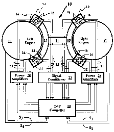
Brief Description of the Drawings
FIG. 1 is a schematic depiction of the electrical interconnection of the
various system components;
FIG. 2 is a cross-sectional end view of one embodiment of active mount
useful in the cancellation system of the present invention; and
FIG. 3 is a cross-sectional end view of a second embodiment of active
mount useful in the cancellation system of the present invention.
Detailed Description of the Preferred Embodiments
The cancellation system of the present invention is depicted in Fig. 1
generally at 10. While the invention is shown in Fig. 1 implemented with an
active
isolation control system, it will be appreciated that the invention may also
be used in
active structural control and active noise control systems, as well. The
active isolation
control system may utilize a waveform generator of the type described in U.S.
Patent
No. 5,487,027 (which issued on January 23, 1996) to produce the sync signals
S1, S2,
S3, and S4. Further, the system may utilize as its digital signal processing
controller 20
a feedforward control processor of U.S. Patent No. 5,619,581 (which issued on
April 8, 1997). Engine support beam 11 extends through a portion of the
fuselage of a
fixed-wing aircraft (not shown) and interconnects first (13) and second (15)
crescent-
shaped support arms. At the extremities of support arms 13, 15 are pairs of
active
mounts 12 and 14. Active mounts 12 support right engine 17 and active mounts
14
support left engine 19. Each mount includes a pair of actuators or force
transmission
elements 16 orthogonally positioned between the engine and the airframe or
exclusively positioned on the structural support side of the mount (Fig. 3)
and two or
more sensors 18 on the structure side of the mount. Active mounts 12, 14 may
be
either the front or rear mounts of the
4
2193080
~1V0 95134769 PCTIUS95f07474
engine with a more conventional passive mount being utilized at the
alternate location.
At least one reference signal is needed, with two sync signals Sl, Sz
~ being shown. These sync signals are transmitted from the right engine 17
b to controller 20 and two sync signals S3, S4 from left engine 19. Signals
Sl,
Sz are representative of the frequency, and phase of NiA and Nzg of the right
engine 17, while S3, S4 are representative of the frequency and phase of N1L
and NzL of left engine 19. These sync signals may be provided by a
tachometer, accelerometer, magnetic pickup or other sensor associated
with the shaft of the turbine, or the like. It will be remembered that when
the term "tachometer" is used herein, it is used representatively of other
similar sensors. Adaptive filters within controller 20 provide weighting
factors which are computed in accordance with a preferred algorithm
(usually LMS or filtered-x LMS) and phase timing to controller signals 21
which are fed to force transmission elements 16 upper and lower mounts 14
through amplifiers 28 to cancel or minimize transmission of the Nlg, Nzx,
N1L and Nzl, vibration tones. Sensors 18 feedback the error signals 23 to the
controller 20 through signal conditioner 22 to initiate correction to the
calculations of the amplitude computed by the algorithm as well as the
phase shift to effect minimization.
As mentioned earlier, the normal control theory involves each error
sensor 18 detecting some amount of each objectionable tone and each
actuator 16 receiving a controller signal 2.1 which attempts to fully cancel
the tones received. If any two of the disturbance tones are close in
frequency, many algorithms are unable to produce a stable control signal
for cancellation. The present solution proposes positioning both the
actuators 16 and the error sensors 18 in the primary disturbance path
between the engines 17, 19 and the support structure 13, 15. Further, the
sensors of right engine mounts 12 must be adequately separated from left
engine mounts 14 that cross coupling of the tones does not occur (i.e., the
component of the right engine tones N~ and NzR received at the left engine
mount 14 will be at least an order of magnitude smaller than those received
from the left engine 19 and can be disregarded). By this positioning, the
system achieves both tonal decoupling (i.e., the left side actuators of mounts
14 will only attempt to control the tones Nu, and NzL, while the actuators of
5
CA 02193080 2001-O1-31
the right mounts 12 will only attempt to control the N1R and N2R tones), and
sensor
decoupling (sensors of right engine mounts 12 will only stimulate actuators of
right
engine mounts 12, while the sensors of left engine mounts 14 will stimulate
actuators
16 of the left engine mounts 14). This decoupling of the response to tones
which are
relatively close in frequency (such as N1R and N1L as well as N2R and N2L)
overcomes
the stability problems which occur with algorithms such as LMS and filtered-x
LMS.
The force transmission elements (actuators) 16 are orthogonally
positioned and may each form a 45° angle with the horizontal as
depicted in Fig. 1.
This has some advantages in that each actuator 16 is able to deliver equal
amounts of
vertical and horizontal cancelling vibrations. In an alternative embodiment,
one
actuator may be positioned to deliver force radially and the second
tangentially with
respect to the engine. In yet a third embodiment, actuators 16 may be
positioned such
that the first extends along a horizontal axis and the second along a vertical
axis (the
upper mounts 12, 14 would have actuators extending downwardly with the lower
mounts having actuators extending upwardly). In any event, it is desired that
the lines
of force along which two of the actuators 16 operate be focalized. That is,
that the
lines of force intersect at the center of gravity of their respective engine
or beyond (as
measured from the actuators). By focalizing the mounts, the mounts can be made
soft
tangentially, and comparatively rigid radially, and still support the engine.
Since the
mount is soft tangentially, little if any force will be transmitted in the
tangential
direction and the number of actuators required for tangential force
cancellation can be
significantly reduced and, in some cases, tangential actuators can be
eliminated.
The active mounts 12, 14 may be of the type described in Fig. 9 of U.S.
Patent No. 5,730,429 (which issued on March 24, 1998). As seen in Fig. 2,
mount 12
(which is equivalent of mount 14) has four orthogonally positioned actuators
16. Four
actuators are required for those actuator types which only have capacity for
force in
one direction. For other actuators, only two units are needed as shown in Fig.
3.
Center frame 24 surrounds pylon 25 while outer frame 26 houses the mount. One
of
the pylon 25 and outer frame 26 are attached to supports 13, 15 while the
other is
attached to its respective engine 17, 19. Generally,
6
~'VO 95134769
PCT/US95107474
center frame 24 will be connected to the supports and the outer frame to the
engines 17, 19. However, Figs. 2 and 3 show the center frame connected to
the engine and the outer frame 26 to the supports 13, 16. Error sensors 18
may be positioned anywhere on the airframe side of the mount and are
shown here attached to the exterior of center frame 24. The Fig. 2
embodiment depicts the actuators as electrohydraulic; however, they may
alternatively be electromagnetic or piezoelectric or replaced by a speaker
without departing from the invention.
Fig. 3 depicts yet another embodiment of mount 14 in which the
actuators take the form of tuned absorbers 16'. The absorber are shown
here on the engine side mounted on center frame 24. These orthogonal,
focalized absorbers reduce vibration transmitted across mount 14 to the
outer frame 26 and, hence to the supports 13, 15. These active absorbers 16'
can be vibrated at any frequency but are tuned to deliver the most force at
one particular frequency, usually N1R and N1L~
By the present invention, the response to two tones which are
relatively close in frequency are decoupled enabling the controller to
compute and transmit cancellation signals which will effectively minimize
the transmission of these signals, be they structural vibration or audible
tones experienced as noise. While these embodiments have been described
in terms of an active mount, the decoupling features of the present
invention are equally applicable to active structural control and active noise
control systems as well. In this regard, the actuators may be replaced by
other output devices such as speakers for active noise control applications.
Another feature of the present invention is the orthogonal positioning of the
actuators within the mount with the focalization of the lines of force in
order to reduce the number of tangential actuators required.
Various modifications, alternatives and changes will become
apparent to one of ordinary skill in the art following a reading of the
foregoing specification. It is intended that all such modifications,
alternatives and changes as fall within the scope of the appended claims be
considered part of the present invention.
7