Sélection de la langue

Search

Sommaire du brevet 2193162 

Énoncé de désistement de responsabilité concernant l'information provenant de tiers

Une partie des informations de ce site Web a été fournie par des sources externes. Le gouvernement du Canada n'assume aucune responsabilité concernant la précision, l'actualité ou la fiabilité des informations fournies par les sources externes. Les utilisateurs qui désirent employer cette information devraient consulter directement la source des informations. Le contenu fourni par les sources externes n'est pas assujetti aux exigences sur les langues officielles, la protection des renseignements personnels et l'accessibilité.

Disponibilité de l'Abrégé et des Revendications

L'apparition de différences dans le texte et l'image des Revendications et de l'Abrégé dépend du moment auquel le document est publié. Les textes des Revendications et de l'Abrégé sont affichés :

  • lorsque la demande peut être examinée par le public;
  • lorsque le brevet est émis (délivrance).
(12) Brevet: (11) CA 2193162
(54) Titre français: DISPOSITIF DE PROTECTION CONTRE L'USURE DE CABLES
(54) Titre anglais: CABLE BIGHT WEAR GUARD ASSEMBLY
Statut: Durée expirée - au-delà du délai suivant l'octroi
Données bibliographiques
(51) Classification internationale des brevets (CIB):
  • F16G 11/02 (2006.01)
  • F16L 3/14 (2006.01)
(72) Inventeurs :
  • NADHERNY, RUDOLPH E. (Etats-Unis d'Amérique)
  • BEALS, STEPHEN H. (Etats-Unis d'Amérique)
(73) Titulaires :
  • IRECO, INC.
(71) Demandeurs :
  • IRECO, INC. (Etats-Unis d'Amérique)
(74) Agent: OSLER, HOSKIN & HARCOURT LLP
(74) Co-agent:
(45) Délivré: 2003-09-30
(22) Date de dépôt: 1996-12-17
(41) Mise à la disponibilité du public: 1997-06-22
Requête d'examen: 1999-03-03
Licence disponible: S.O.
Cédé au domaine public: S.O.
(25) Langue des documents déposés: Anglais

Traité de coopération en matière de brevets (PCT): Non

(30) Données de priorité de la demande:
Numéro de la demande Pays / territoire Date
576,789 (Etats-Unis d'Amérique) 1995-12-21

Abrégés

Abrégé français

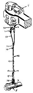
ispositif de protection contre l'usure de câble destiné à protéger le mou d'un câble porteur en l'empêchant de frotter directement contre la surface d'une ouverture telle que celle pratiquée dans une bride située sur le dessous d'un accrocheur d'automotrice ou l'ouverture dans la bride d'une tête d'accouplement. Le dispositif de protection est particulièrement utile lorsqu'il est employé avec l'assemblage de soutien ajustable décrit dans le brevet no 4 519 564 du 28 mai 1985. Le dispositif de protection pour le mou d'un câble passant dans l'ouverture de la bride d'un accrocheur d'automotrice a généralement la forme d'un U et il est fabriqué, au moins, dans un matériau relativement rigide. Le dispositif comprend de préférence une cannelure externe dans laquelle le mou est fixé sans être trop serré de façon à ce qu'il puisse bouger et s'ajuster par rapport aux différentes longueurs du câble de chaque c"té du mou. Le dispositif de protection pour le mou d'un câble passant dans l'ouverture de la bride d'une tête d'accouplement a aussi la forme d'un U, sauf que les dispositions pour lui permettre de bouger ne sont peut-être pas nécessaires.


Abrégé anglais


A cable wear guard for shielding a bight in a
support cable from direct rubbing contact with the surface
in an aperture such as the aperture in the flange on the
underside of a rail car coupler or the aperture on the
flange on a glad hand. The cable wear guard is
particularly useful with the adjustable support assembly
disclosed in Patent No. 4,519,564 dated May 28, 1985. The
cable wear guard for the bight in a cable passing through
an aperture in the flange on a car coupler is generally U-
shaped and formed of at least relatively rigid material.
Preferably, the cable wear guard has an outwardly facing
groove in which the cable bight is secured with a slippage
fit so as to allow for adjustment for differences in the
initial lengths of the opposing sides of a bight. The
wear guard for a cable bight passing through the aperture
in the flange on a glad hand is likewise U-shaped but
provision for cable slippage therein may not be necessary.

Revendications

Note : Les revendications sont présentées dans la langue officielle dans laquelle elles ont été soumises.


-7-
WHAT IS CLAIMED IS:
1. In combination, a cable wear guard and an elongated
flexible support, said combination being for use in
supporting a glad hand on a rail car from the
apertured bracket depending from the coupler on the
rail car,
said elongated flexible support comprising a
plurality of inelastic, flexible and stiff cables and
a plurality of retaining members spaced along and
rigidly secured to said stiff cables, said cables and
said retaining members forming, in combination, a
series of stiff elongated eyes, said stiff cables of
the elongated eyes being sufficiently resilient in
their generally transverse dimension such that said
elongated eyes will expand and snap back to a
generally closed position, said stiff cables of the
elongated eyes being biased toward a generally closed
orientation to provide a wedging portion at which at
least a section of each of said stiff cables is
substantially juxtaposed with respect to the other,
at least one of said inelastic, flexible and stiff
cables extends beyond an endmost retaining member,
said at least one cable having a free end, said free
end includes one-way means, said one-way means having
a leading end and a trailing end, each said elongated
eye and its wedging portion being sized and
structured to permit passage of said one-way means
through said elongated eye, said trailing end of the
one-way means having an integral stop that is sized
to provide a rigid abutment between said elongated
eye and said trailing end of the one-way means, and
said abutment restrains passage of the one-way means
in a direction toward said abutment between the
elongated eye and the integral stop, said one-way
means being insertable through the aperture in said
apertured bracket prior to being inserted through the
elongated eye adjacent said endmost retaining member

-8-
so that said free end will form a loop at the end of
said elongated flexible support with said loop having
a bight where it passes through said aperture; and
said cable wear guard being generally U-shaped,
formed of a wear-resistant material, fitting on said
bight in said free end, and being insertable through
said aperture whereby the bight of said wear guard
will have direct contact with the interior of said
aperture thereby shielding said free end from direct
contact with said interior surface.
2. In the combination of claim 1, said wear guard
fitting freely on said bight in said free end so that
said bight is slippable in said wear guard allowing
opposite sides of said loop to equalize.
3. In the combination of claim 2, said wear guard being
formed of a relatively rigid material and having an
outwardly facing groove extending substantially from
end-to-end into which said free end is received, said
groove being sufficiently closed adjacent its
opposite ends whereby said bight in said free end
will be retained in said groove.
4. In the combination of claim 3, said groove being
sufficiently closed at at least one location
intermediate its opposite ends so as to retain said
bight in said groove at each said intermediate
location.
5. In the combination of claim 4, said intermediate
location is approximately mid-way between said
opposite ends.
6. In the combination of claim 2, said wear guard being
a piece of tube.

-9-
7. In the combination of claim 3, said elongated
flexible support having a second free end on the end opposite
said first-mentioned free end insertable through an aperture
in a bracket on a said glad hand, and said second free end
includes second one-way means, said second one-way means
having a leading end and a trailing end, a said elongated eye
adjacent said second free end and its wedging portion being
sized and structured to permit passage of said second one-way
means through said last mentioned elongated eye, said trailing
end of said second one-way means having an integral stop that
is sized to provide a rigid abutment between said last
mentioned elongated eye and said trailing end of. said second
one-way means, and said abutment restrains passage of said
second one-way means in a direction toward said abutment
between said last mentioned elongated eye and the integral
stop, and cable wear guard on the bight of said second free
end.
8. A cable wear guard for shielding a bight in a cable
from direct rubbing contact with a surface on which the bight
of the cable would otherwise rub, comprising, a generally U-
shaped member formed of a relatively rigid material and having
an outwardly facing cable-receiving groove extending
substantially from end-to-end in which the bight of a cable is
free to slip, said groove being sufficiently closed adjacent
its opposite ends whereby the bight of a cable is retained in
said groove.
9. The cable wear guard of claim 8 wherein said groove
therein is sufficiently closed at at least one intermediate
location to retain a cable in said groove at said location.

-10-
10. The cable wear guard of claim 9 wherein said
intermediate location is approximately mid-way
between said opposite ends.
11. In combination with a railway car having a car
coupler and an air brake hose with a glad hand on its
end, said coupler having a depending bracket with a
transverse aperture therein for receiving a bight in
a cable forming part of a support for the glad hand,
a cable wear guard for shielding the bight in the
cable from direct rubbing contact with the surface of
said aperture, comprising, a generally U-shaped
member formed of a rigid or relatively rigid material
inserted in said aperture in a downwardly oriented
position with its bight portion bearing down on the
bottom surface of said aperture.
12. The combination of claim 11, said U-shaped member
having an outwardly facing cable-receiving groove
extending substantially from end-to-end in which the
bight of a cable is free to slip, said groove being
sufficiently closed adjacent its opposite ends
whereby the bight of a cable is retained in said
groove.
13. In the combination of claim 12 the cable wear guard
called for therein having said groove therein
sufficiently closed at at least one intermediate
location to retain a cable in said groove at said
location.
14. In the combination of claim 13 the cable wear guard
called for therein having said intermediate location
approximately mid-way between said opposite ends.

-11-
15. In the combination of claim 12 wherein said glad hand
has a bracket with a second transverse aperture
therein for receiving a bight in said cable, a second
wear guard for shielding a second bight in said cable
from direct rubbing contact with the surface of said
second aperture comprising a second generally U-
shaped member formed of a rigid or relatively rigid
material inserted in said second aperture with its
bight portion bearing upwardly on the upper surface
of said second aperture, said second generally U-
shaped member having an outwardly facing cable-
receiving groove extending substantially from end to
end in which said cable is secured.

Description

Note : Les descriptions sont présentées dans la langue officielle dans laquelle elles ont été soumises.


CA 02193162 2002-08-28
CABLE BIGHT WEAR GUARD ASSEMBLY
SPECIFICATION
Background and Description of the Invention
This invention relates, generally, to improvements and
innovations in wear guards or thimble fo:r sluielding the bights
in cables from direct rubbing contact with wear surfaces which
cause the cable material to fray and ultimately break if not
replaced. More particularly, the invention relates to cable
wear guards and their use to protect the bights in cables
passing through apertures in railway car couplers, the cables
forming parts of flexible elongated supports for supporting
the glad hands on the ends of the air brake hoses.
There is disclosed :in Nadherny Patent 4,519,564 dated May
28, 1985, assigned to Ireco, Inc. the assignee of the present
invention, an adjustable support assembly which has multiple
uses, one of the which is to support the glad hands on air
brake hoses of railway cars from the rai:iway car couplers.
In FIGS. 1 and 9 of Patent 4,519,564, the glad hands on
the ends of air brake hoses are shown being supported from
apertured brackets on railway car couplers, with cables
forming parts of the supports and passing directly through the
apertures in the brackets on the couplers. It has been found
in practice that the more or less constant rubbing action of
the bights in the cables against the bracket apertures due to
relative movement between the glad hands and the car couplers
when trains are in motion, and the considerable strain
suddenly imposed on the bights when cars are uncoupled and the
glad hands are jerked apart, causes the individual strands of
the cables to wear through and break so l.hat the bights in

_ 21.93162
-2-
the cables become frayed and the supports for the glad
hands will fail if not replaced in time. Excessive wear
may also occur at the bights in cables that pass through
apertures in the brackets on the glad hands as a result of
the rubbing which occurs between these bights in the
cables and the aperture surfaces.
In accordance with the present invention, it has
been found that the useful lives of the adjustable support
assemblies disclosed in Patent 4,519,564 can be greatly
extended by using cable wear guards or thimbles to shield
the bights in cables which have previously had direct
rubbing contact with the surfaces of the apertures in the
brackets on the underside of railway couplers. These wear
guards are of such design and construction as to allow the
bight portions of the cables to freely slip within the
wear guards. However, in use, the rubbing action occurs
primarily between the surfaces of the wear guards and the
surfaces of the apertures with a minimal amount of rubbing
or slipping action occurring between the bights in the
cable and the wear guards themselves.
The wear guards of the present invention are
inexpensive and conveniently placed on the cables and
inserted through the apertures in the brackets which
depend from the undersides of the railway car couplers as
well as through the apertures in the brackets on the tops
of glad hands.
Accordingly, the primary object of the
invention, generally stated, is the provision of cable
wear guards for combined use with the supports for glad
hands on air brake hoses from railway car couplers, which
cable wear guards are inexpensive to produce and assemble
on the cables and which serve to shield the bights in the
cables from wearing engagement against the surfaces of the
apertures in the couplers and glad hand support brackets
and as a result, greatly extend the lives of the cables
and the supports of which the cables form a part.

2193152
-3-
For a more complete understanding of the nature
and scope of the invention, reference may be had to the
following description of preferred embodiments of the
invention taken in connection with the accompanying
drawings, wherein:
Brief Description of the Drawings
FIG. 1 is a perspective view of a glad hand on a
rail car air brake hose being supported from a bracket on
the underside of a car coupler with a cable wear guard of
the present invention in place on the bight of a cable
passing through the aperture in the depending bracket and
showing a somewhat different wear guard in place on the
bight of the cable passing through the aperture in the
glad hand support bracket.
FIG. 2 is a fragmentary perspective view showing
a second embodiment of the invention;
FIG. 3 is a side elevational view of the upper
cable wear guard shown in FIGS. 1 and 2 for the car
coupler;
FIG. 4 is a side view taken on line 4-4 of
FIG. 3;
FIG. 5 is a top plan view taken on line 5-5 of
FIG. 3;
FIG. 6 is a bottom plan view taken on line 6-6
of FIG. 3;
FIG. 7 is a fragmentary perspective view showing
a third embodiment; and
FIG. 8 is a perspective view corresponding to
FIG. 1 of Patent No. 4,519,564 illustrating the prior art.
Referring to FIG. 1, a glad hand indicated
generally at 5 on the end of an air brake hose 6 is shown
being supported from a rail car coupler indicated
generally at 7. The coupler 7 has a depending flange or
bracket 8 which has a transverse aperture 10 in which is
located a cable wear guard or thimble of the present
invention indicated generally at 11.

2193162
-4-
The glad hand 5 is supported from the coupler 7
by an elongated flexible support indicated generally at 12
which may correspond to the adjustable support assembly
shown in FIG. 8 and indicated generally at 11 in FIG. 1 of
Patent 4,519,564. The upper end of the support 12
(FIG. 1) is in the form of a cable 13 which is usually,
but not necessarily, formed of woven wire construction.
As described in Patent 4,519,564, the support 12 includes
a series of "wedging elongated eyes" 14-14 formed by
securing two lengths of cable together at spaced points.
The free length of cable 13 at the upper end of the
support 12 as well as a similar free length of cable 15 at
its lower end each has a bullet shaped member 16 and 17,
respectively, swaged on the end of the cable. As
described in Patent 4,519,,564, on installation, the bullet
shaped members 16 and 17 are forced through spreadable
eyes 14. Once the end pieces 16 and 17 have been pushed
all the way through the eyes 14 they will remain in place.
Referring to FIG. 8, (prior art) it will be seen
that the upper length of cable that passes through the
aperture in the flange or bracket depending from the car
coupler has a bight portion A which rubs on the bottom
surface of the aperture B due both to the normal swaying
action of the air brake hose and glad hand during train
movement and the jerking action which occurs when
connected cars are uncoupled and the glad hands are jerked
apart. Similarly, the cable on the lower end of the
support has a bight portion C where the cable passes
through an aperture in the flange or bracket on the glad
hand.
For a description of the cable wear guard or
thimble 11, reference may be had to FIGS. 1 and 3-6. As
will be noted from FIGS. 1 and 3, the cable wear guard 11
is generally U-shaped, and when assembled as shown in FIG.
1, it will be in its inverted or downwardly oriented
position. The cable guard 11 may be formed from crimpable
metal, or from a suitable plastic which will be durable

2193162
-5-
over long periods of use under the extreme weather
conditions to which railway cars are exposed. For
example, the cable wear guard 1l may be suitably stamped
from malleable steel which is preferably galvanized or
otherwise surface-protected.
The cable wear guard 11 is formed so that it has
an outwardly facing groove 20 extending from end to end in
which the cable 13 fits and is free to slip. At their
distal ends, the legs of the U-shaped cable wear guard 11
are bifurcated as indicated at 21-21. The resulting ends
are crimped together so as to trap and retain the cable 13
within the opposing ends of the groove 20. Preferably, at
one location intermediate the distal ends, preferably at
the bight portion of the thimble 11, the outer edges of
the groove are crimped together as indicated at 22 so as
to close the groove 20 and thereby retain the cable in
place in the bight of the guard 11.
Slippage between the cable 13 and the cable wear
guard 11 is allowed and provided for so as to compensate
for initial differences in lengths of the opposite sides
of the loop in the cable 13. However, once this
adjustment for length slippage has occurred, there will be
little or no appreciable additional slippage between the
cable and the wear guard and thereafter the rubbing action
will all take place between the inside of the bight
portion of the cable wear guard 1l and the surface of the
aperture 10.
While the bight portion of the lower length of
cable 15 is also subjected to wearing action, it is
usually sufficient to provide this bight with a crimped on
wear guard 25 which does not need to allow for relative
slippage between bight on the cable 15 and the wear
guard 25.

2193162
-6-
In FIG. 2, an embodiment of the invention is
shown wherein a cable wear guard 30 is provided on the
bight portion of a short length of cable 31, one end of
which is bent over on itself so as to form a loop 32
maintained by a crimped on collar 33 while the opposite
end is provided with a bullet shaged end member 34 which
is inserted through the loop 32 as shown. A glad hand
support such as the support 12 in FIG. 1 may be supported
by the cable 31 by passing the bight on cable 35 through
the loop 32 as shown. The cable wear guard 30 may
correspond to the cable wear guard 11 and is shown passing
through an aperture 36 in a bracket 37 on the other side
of a car coupler.
A third embodiment of the invention is shown in
FIG. 7 wherein the upper end of an elongated flexible
support is indicated generally at 40 corresponding to the
elongated flexible support 12 in FIG. 1. The bight of
free end 41 of the support 40 is shown passing through the
aperture 42 in a coupler bracket 43. Prior to the swaging
of the bullet shaped end member 44 on the cable free end
41, the cable is threaded through a thimble or wear guard
in the form of U-shaped tube 45 the bight portion of which
engages the bottom of the aperture 42. The tube 45 may be
formed of a wear-resistant, weather-proof plastic with an
inside diameter which allows the cable 41 to slip freely
therein so that the lengths of the opposite sides of the
loop in the free end are allowed to become equalized.
It will be apparent to those skilled in this art
that the invention can be embodied in other forms.
Accordingly, this invention is to be construed and limited
only by the scope of the appended claims.

Dessin représentatif
Une figure unique qui représente un dessin illustrant l'invention.
États administratifs

2024-08-01 : Dans le cadre de la transition vers les Brevets de nouvelle génération (BNG), la base de données sur les brevets canadiens (BDBC) contient désormais un Historique d'événement plus détaillé, qui reproduit le Journal des événements de notre nouvelle solution interne.

Veuillez noter que les événements débutant par « Inactive : » se réfèrent à des événements qui ne sont plus utilisés dans notre nouvelle solution interne.

Pour une meilleure compréhension de l'état de la demande ou brevet qui figure sur cette page, la rubrique Mise en garde , et les descriptions de Brevet , Historique d'événement , Taxes périodiques et Historique des paiements devraient être consultées.

Historique d'événement

Description Date
Inactive : Périmé (brevet - nouvelle loi) 2016-12-17
Inactive : Lettre officielle 2007-05-09
Inactive : Paiement - Taxe insuffisante 2007-05-04
Inactive : Grandeur de l'entité changée 2007-02-28
Inactive : Paiement correctif - art.78.6 Loi 2007-01-29
Inactive : CIB de MCD 2006-03-12
Accordé par délivrance 2003-09-30
Inactive : Page couverture publiée 2003-09-29
Inactive : Demande ad hoc documentée 2003-07-23
Inactive : Supprimer l'abandon 2003-07-16
Inactive : Correspondance - Poursuite 2003-07-09
Inactive : Taxe finale reçue 2003-05-02
Réputée abandonnée - les conditions pour l'octroi - jugée non conforme 2003-05-01
Préoctroi 2003-04-29
Lettre envoyée 2002-11-01
Un avis d'acceptation est envoyé 2002-11-01
Inactive : Approuvée aux fins d'acceptation (AFA) 2002-09-30
Modification reçue - modification volontaire 2002-08-28
Inactive : Dem. de l'examinateur par.30(2) Règles 2002-05-30
Inactive : Renseign. sur l'état - Complets dès date d'ent. journ. 1999-03-19
Lettre envoyée 1999-03-19
Inactive : Dem. traitée sur TS dès date d'ent. journal 1999-03-19
Exigences pour une requête d'examen - jugée conforme 1999-03-03
Toutes les exigences pour l'examen - jugée conforme 1999-03-03
Inactive : Grandeur de l'entité changée 1998-05-27
Demande publiée (accessible au public) 1997-06-22

Historique d'abandonnement

Date d'abandonnement Raison Date de rétablissement
2003-05-01

Taxes périodiques

Le dernier paiement a été reçu le 2002-10-02

Avis : Si le paiement en totalité n'a pas été reçu au plus tard à la date indiquée, une taxe supplémentaire peut être imposée, soit une des taxes suivantes :

  • taxe de rétablissement ;
  • taxe pour paiement en souffrance ; ou
  • taxe additionnelle pour le renversement d'une péremption réputée.

Veuillez vous référer à la page web des taxes sur les brevets de l'OPIC pour voir tous les montants actuels des taxes.

Historique des taxes

Type de taxes Anniversaire Échéance Date payée
TM (demande, 2e anniv.) - petite 02 1998-12-17 1998-11-02
Requête d'examen - petite 1999-03-03
TM (demande, 3e anniv.) - petite 03 1999-12-17 1999-09-27
TM (demande, 4e anniv.) - petite 04 2000-12-18 2000-10-11
TM (demande, 5e anniv.) - petite 05 2001-12-17 2001-09-28
TM (demande, 6e anniv.) - petite 06 2002-12-17 2002-10-02
Taxe finale - petite 2003-04-29
TM (brevet, 7e anniv.) - petite 2003-12-17 2003-09-29
TM (brevet, 8e anniv.) - générale 2004-12-17 2004-12-13
TM (brevet, 9e anniv.) - générale 2005-12-19 2005-11-21
TM (brevet, 10e anniv.) - générale 2006-12-18 2006-11-30
2007-01-29
TM (brevet, 11e anniv.) - générale 2007-12-17 2007-11-30
TM (brevet, 12e anniv.) - générale 2008-12-17 2008-12-01
TM (brevet, 13e anniv.) - générale 2009-12-17 2009-12-01
TM (brevet, 14e anniv.) - générale 2010-12-17 2010-11-30
TM (brevet, 15e anniv.) - générale 2011-12-19 2011-11-30
TM (brevet, 16e anniv.) - générale 2012-12-17 2012-11-30
TM (brevet, 17e anniv.) - générale 2013-12-17 2013-12-02
TM (brevet, 18e anniv.) - générale 2014-12-17 2014-12-15
TM (brevet, 19e anniv.) - générale 2015-12-17 2015-12-14
Titulaires au dossier

Les titulaires actuels et antérieures au dossier sont affichés en ordre alphabétique.

Titulaires actuels au dossier
IRECO, INC.
Titulaires antérieures au dossier
RUDOLPH E. NADHERNY
STEPHEN H. BEALS
Les propriétaires antérieurs qui ne figurent pas dans la liste des « Propriétaires au dossier » apparaîtront dans d'autres documents au dossier.
Documents

Pour visionner les fichiers sélectionnés, entrer le code reCAPTCHA :


Pour visualiser une image, cliquer sur un lien dans la colonne description du document. Pour télécharger l'image (les images), cliquer l'une ou plusieurs cases à cocher dans la première colonne et ensuite cliquer sur le bouton "Télécharger sélection en format PDF (archive Zip)" ou le bouton "Télécharger sélection (en un fichier PDF fusionné)".

Liste des documents de brevet publiés et non publiés sur la BDBC .

Si vous avez des difficultés à accéder au contenu, veuillez communiquer avec le Centre de services à la clientèle au 1-866-997-1936, ou envoyer un courriel au Centre de service à la clientèle de l'OPIC.


Description du
Document 
Date
(aaaa-mm-jj) 
Nombre de pages   Taille de l'image (Ko) 
Dessin représentatif 1998-03-30 1 14
Dessin représentatif 2002-05-31 1 6
Page couverture 2003-08-27 1 40
Page couverture 1997-04-21 1 16
Abrégé 1997-04-21 1 26
Description 1997-04-21 6 273
Revendications 1997-04-21 5 182
Dessins 1997-04-21 2 50
Description 2002-08-28 6 274
Revendications 2002-08-28 5 185
Rappel de taxe de maintien due 1998-08-18 1 115
Accusé de réception de la requête d'examen 1999-03-19 1 178
Avis du commissaire - Demande jugée acceptable 2002-11-01 1 163
Correspondance 1998-05-20 2 40
Correspondance 1998-05-20 2 46
Correspondance 2003-05-02 1 35
Taxes 2004-12-14 1 38
Correspondance 2007-05-09 1 15